Section 1
SAFETY
1
1.1 GENERAL
Sullair Corporation designs and manufactures all
of its products so they can be operated safely.
However, the responsibility for safe operation rests
with those who use and maintain these products.
The following safety precautions are offered as a
guide which, if conscientiously followed, will mini-
mize the possibility of accidents throughout the
useful life of this equipment. Read the CIMA Safety
Manual prior to compressor operation and towing,
if applicable in your area.
The air compressor should be operated only by
those who have been trained and delegated to do
so, and who have read and understood this Opera-
tor’s Manual. Failure to follow the instructions, pro-
cedures and safety precautions in this manual can
result in accidents and injuries.
NEVER
start the air compressor unless it is safe to
do so.
DO NOT
attempt to operate the air compres-
sor with a known unsafe condition. Tag the air com-
pressor and render it inoperative by disconnecting
the battery so others who may not know of the un-
safe condition will not attempt to operate it until the
condition is corrected.
Use and operate the air compressor only in full
compliance with all pertinent OSHA requirements
and/or all pertinent Federal, State and Local codes
or requirements.
DO NOT
modify the compressor except with writ-
ten factory approval.
Each day walk around the air compressor and in-
spect for leaks, loose or missing parts, damaged
parts or parts out of adjustment. Perform all recom-
mended daily maintenance.
Inspect for torn, frayed, blistered or otherwise dete-
riorated and degraded hoses. Replace as re-
quired.
NOTE
Estimated hose life based on a 5---day 8---hour
work week is 3 years. These conditions exist on
an 8---hour shift only. Any other operation of the
equipment other than 8---hour shifts would derate
the hose life based on hours of operation.
1.2 TOWING
(I)
A. PREPARING TO TOW
WARNING
!
DO NOT tow the compressor should its weight ex-
ceed the rated limit of the tow vehicle, as the vehi-
cle may not brake safely with excess weight. See
rated limit in tow vehicle Operator’s Manual, and
review its instructions and other requirements for
safe towing.
1. Prior to hitching the air compressor to the tow
vehicle, inspect all attachment parts and equip-
ment, checking for (i) signs of excessive wear or
corrosion, (ii) parts that are cracked, bent,
dented or otherwise deformed or degraded, and
(iii) loose nuts, bolts or other fasteners. Should
any such condition be present,
DO NOT TOW
until the problem is corrected.
2. Back the tow vehicle to the compressor and
position it in preparation for coupling the com-
pressor.
3. If the compressor is provided with a drawbar
latched in the vertical upright position, carefully
unlatch drawbar and lower it to engage the cou-
pling device. If not, raise drawbar to engage
coupling device or otherwise couple the com-
pressor to the towing vehicle.
WARNING
!
This equipment may be tougue heavy. DO NOT
attempt to raise or lower the drawbar by hand if
the weight is more than you can safely handle.
Use a lifting device such as a jack or chain fall if
you cannot lift or lower it without avoiding injury
to yourself or others. Keep hands and fingers
clear of the coupling device and all other pinch
points. Keep feet clear of drawbar to avoid injury
in case it should slip from your hands.
4. Make sure the coupling device is fully en-
gaged, closed and locked.
5. If chains are provided, pass each chain
through its point of attachment on the towing ve-
hicle; then hook each chain to itself by passing
the grab hook over (not through) a link. Cross
chains under front of drawbar before passing
them through points of attachment on towing
vehicle to support front of drawbar in case it
should accidentally become uncoupled.
6. Make sure that the coupling device and adja-
cent structures on the towing vehicle (and also, if
utilized, chain adjustment, brake and/or electri-
cal interconnections)
DO NOT
interfere with or
restrict motion of any part of the compressor, in-
cluding its coupling device, with respect to the
towing vehicle when maneuvering over any an-
ticipated terrain.
7. If provided, make sure chain length, brake
and electrical interconnections provide suffi-
cient slack to prevent strain when cornering and
maneuvering, yet are supported so they cannot
drag or rub on road, terrain or towing vehicle sur-
faces which might cause wear that could render
them inoperative.
WARNING
!
Retract the front stabilizer leg only after attaching
the compressor to the tow vehicle. Remove the
pin on top of the drawbar and place the stabilizer
leg in its full---up position. Reinsert the pin and
make sure it is secured in place prior to towing.
If a retractable caster wheel is provided, pull the
lock pin and fold and raise the caster wheel, mak-
ing sure the pin is re---engaged to secure the cast-
er wheel in the full---up and locked position with
the wheel horizontal prior to towing.
Summary of Contents for 175
Page 6: ...NOTES ...
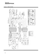
Page 22: ...Section 2 DESCRIPTION 16 Figure 2 7 Electrical System ...
Page 52: ...Section 7 ILLUSTRATIONS AND PARTS LIST 46 7 4A RADIATOR COMPRESSOR FLUID SYSTEM 175 MODELS ...
Page 54: ...Section 7 ILLUSTRATIONS AND PARTS LIST 48 7 4A RADIATOR COMPRESSOR FLUID SYSTEM 175 MODELS ...
Page 78: ...Section 7 ILLUSTRATIONS AND PARTS LIST 72 7 9B ELECTRICAL PARTS 185 185H MODELS ...
Page 80: ...Section 7 ILLUSTRATIONS AND PARTS LIST 74 7 10 INSTRUMENT PANEL PARTS ALL MODELS ...
Page 82: ...Section 7 ILLUSTRATIONS AND PARTS LIST 76 7 11A AIR INLET AND EXHAUST 175 MODELS ...
Page 84: ...Section 7 ILLUSTRATIONS AND PARTS LIST 78 7 11B AIR INLET AND EXHAUST 185 185H MODELS ...
Page 86: ...Section 7 ILLUSTRATIONS AND PARTS LIST 80 7 12 FUEL TANK CONNECTIONS ALL MODELS ...
Page 88: ...Section 7 ILLUSTRATIONS AND PARTS LIST 82 7 13A CANOPY PARTS 175 MODELS ...
Page 90: ...Section 7 ILLUSTRATIONS AND PARTS LIST 84 7 13B CANOPY PARTS 185 185H MODELS ...
Page 92: ...Section 7 ILLUSTRATIONS AND PARTS LIST 86 7 14 DECALS ...
Page 94: ...Section 7 ILLUSTRATIONS AND PARTS LIST 88 7 14 DECALS ...
Page 96: ...Section 7 ILLUSTRATIONS AND PARTS LIST 90 7 14 DECALS ...
Page 99: ......


