


-
24
-
© STULZ GmbH, Hamburg
-
24
-
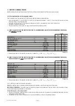
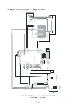
For the humidifiers from 25 to 65 kg/h the electronic board without TAM is used: in its place are 2 terminals that are con-
nected to the TAM fitted in electrical panel on the unit.
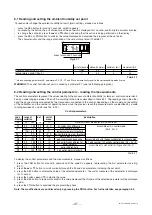
Table 6.3.1 below shows the terminal blocks and the corresponding connections (functions and electrical specifications):
Tab. 6.3.1
termin. function
electrical specifications
1I
outlet probe signal
input
input impedance:
50
Ω
if programmed for 0 to 20 mA or
4 to 20 mA
60
Ω
if programmed for 0 to 1 V or
0 to 10 V or 2 to 10 V
2I
GND
3I
≈
32 Vdc
derived from rectifying 24 Vac;
max 250 mA
4I
12 Vdc stabilised
precision ± 5%; Imax = 50 mA
5I
room probe signal
input or signal from
the external
regulator
input impedance:
50
Ω
if programmed for 0 to 20 mA or
4 to 20 mA
60
Ω
if programmed for 0 to 1 V or
0 to 10 V or 2 to 10 V
6I
GND
7I
8I
remote enabling
imposes an external NO contact;
Rmax = 50
Ω
; Vmax = 24 Vdc;
Imax = 10 mAdc;
humidifier enabled= contact closed
1H
NO alarm contact
250 V; 8 A resistive; 2 A inductive
2H
common alarm
contact
3H
NC alarm contact
1G
2G
NO dehumidification
contact
250 V; 8 A with resistive load;
2 A with inductive load
1J
≈
28 V
derived from rectifying 24 Vac;
max 250 mA
2J
L +
RS-485 standard
3J
L -
4J
GND
1K
remote button switch
NC contact
2K
terminal block
common contact
3K
for DRAIN control
with simultaneous
disabling of power
supply
NO contact