


-
12
-
© STULZ GmbH, Hamburg
-
12
-
A
B
C
D
E
F
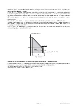
300
200
200
400
700 <0,5°
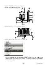
Modell SEH 001...008 SEH 010...015 SEH 025...045 SEH065
X
220
220
310
400
Y
500
590
725
785
Z
115
38
Z’
112
A
B
C
D
E
F
X
A
B
C
D
E
F
300
200
200
400
700 <0.5°
Model SEH 001...008 SEH 010...015 SEH 025...045 SEH065
X
220
220
310
400
Y
500
590
725
785
Z
115
38
Z’
112
A
B
C
D
E
F
X
A
B
C
D
E
F
300
200
200
400
700 <0,5°
Modell SEH 001...008 SEH 010...015 SEH 025...045 SEH065
X
220
220
310
400
Y
500
590
725
785
Z
115
38
Z’
112
A
B
C
D
E
F
X
A
B
C
D
E
F
300
200
200
400
700 <0,5°
Modell SEH 001...008 SEH 010...015 SEH 025...045 SEH065
X
220
220
310
400
Y
500
590
725
785
Z
115
38
Z’
112
A
B
C
D
E
F
X
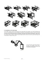
3 MOUNTING
3.1 Receipt and storage
Check that the humidifier is intact upon receipt and immediately notify the shipping agent, in writing, of any damage that
may be due to impro per or careless transport. Move the humidifier to the place of installation before removing it from the
packaging, grasping the neck only from below the base. Open the box, remove the layer of protective material and take out
the humidifier, keeping it vertical at all times; only remove the protective bag when installing the unit.
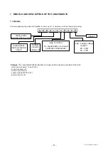
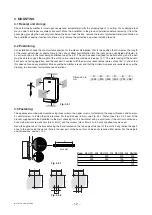
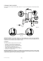
3.2 Positioning
For installation choose the most suitable position for the steam distribution, that is the position that minimises the length
of the steam outlet pipe, or alternatively, in the case of direct humidification into the room using a ventilated distributor, in
a central position in the room being humidified (see Chap. 5). The unit has been designed for wall-mounting, and the wall
must be able to support the weight of the unit in normal operating conditions (see par. 13.1). The metal casing of the humidi-
fier heats up during operation, and the rear part in contact with the wall may reach temperatures of over 60 °C; check that
this does not cause any pro blems. Make sure the humidifier is level, and that the minimum spaces are respected as per the
drawing, to allow room for maintenance operations.
Fig. 3.2.1
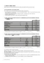
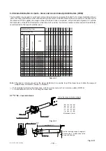
3.3 Fastening
The appliance must be wall-mounted using three screws: two upper screws, for fastening the support bracket, and one low-
er, central screw, to fasten the unit into place. For the distances (in mm), see Fig. 3.3.1. Fasten (see Figs. 3.3.1 and .2) the
bra cket supplied with the humidifier to the wall, checking that it is horizontal using a spirit level, if the unit is mounted on a
brick wall, plastic screw anchors (diam. 8 mm) and the screws (diam. 5mm x L= 50 mm) supplied may be used.
Hang the appliance on the bracket using the band located on the top edge of the rear of the unit. Finally, fasten the appli-
ance to the wall using the central hole in the rear part of the base, this can be easily reached from below. For the weights
and dimensions, see par. 13.1.
Fig. 3.3.1
Fig. 3.3.2
Dimension in
mm
bracket
A
B
C
D
E
F
300
200
200
400
700 <0.5°
Model SEH 001...008 SEH 010...015 SEH 025...045 SEH065
X
220
220
310
400
Y
500
590
725
785
Z
115
38
Z’
112
A
B
C
D
E
F
X


