


-
23
-
© STULZ GmbH, Hamburg
-
23
-
TA 20
TA RATE
TA RATE
TA RATE
ON
ON
ON
1 2
3
4
TA 60
1 2
3
4
TA 40
1 2
3
4
TAM
U
N
IV
.
L.
01
10
10
19
5
100
300
500
700
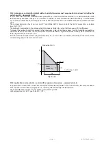
EXTERNAL TAM
1 Turn
2 Turns
TA RATE TA RATE TA RATE
1I
2I
3I
4I
5I
6I
7I
8I
1H
2H
3H
1G
2G
1J
2J
3J
4J
1K
2K
3K
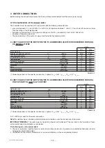
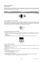
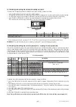
1. terminal block G (dehumidification contact);
2. terminal block H (alarm contact);
3. terminal block K (manual remote DRAIN
command);
4. terminal block I (control signals);
5. terminal block J (to remote terminal or
supervisory system);
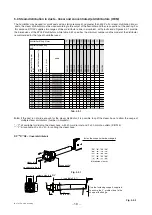
6. dip-switch for selecting TA RATE
Amperometric transformer configuration; the switch position on the board is shown in fig. 6.1.2 and fig. 6.1.3
Fig. 6.1.2
Fig. 6.1.3
6.2 Checking the voltage of the auxiliary circuit transformer
The multi-voltage auxiliary circuit transformer has two primary windings (for 230 V and 400 V) or three primary windings (for
200, 208 and 460 V) and one secondary winding (24 V). The transformer is connected and checked in the factory, according
to the rated voltage. The transformer primary is protected by 10.3 x 38 mm cylindrical fuses on the disconnecting switch,
with the ratings indicated in Table 10.3.1.1.
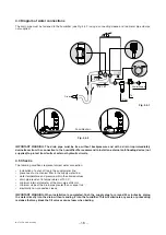
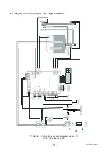
6.3 Main control board
Version H
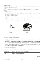
The auxiliary connections, which depend on the model and the controller, must be made by inserting the cables from the
outside into the electrical panel compartment using the smaller cable gland, located on the base of the humidifier until
reaching, through the channel in the internal partition, the removable screw terminal block located on the main control
board, as shown in Fig. 6.3.1 and described in the following paragraph:
Fig. 6.3.1


