27
© STULZ GmbH – all rights reserved EN/06.2017/G18D
cyberair 3PrO cw2 Original instructiOns
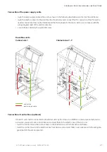
Connection of the power supply cable
control line
power supply cable
• route the power supply cable in the unit as shown in the following illustrations and fix it at the unit frame.
• route the electric cable into the electrical box from below and connect the PE conductor at the PE rail, the
neutral conductor at the neutral terminal and the three phases to the main switch, in accordance with the
wiring diagram (part of the unit documents).
• secure these cables by the pull relief screw.
Downflow units
Cabinet size 1
Cabinet sizes 2 - 7
Connection of control lines (optional)
If the A/C unit shall be connected to other Stulz units by the IO bus, to a BMS or contains opional extensions
as louvers, you must route control lines and connect them in the electric box of the A/C unit.
• route the control lines in the unit as shown in the illustrations and fix them at the unit frame.
• route the control lines into the electrical box from below and connect them in accordance with the wiring dia
-
gram (part of the unit documents).


