25
h
p = -300Pa
3 cm
>10 cm
© STULZ GmbH – all rights reserved EN/06.2017/G18D
cyberair 3PrO cw2 Original instructiOns
5.3.3 Condensate drain connection
Syphon installation
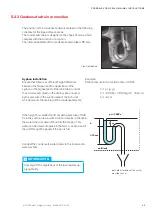
Ensure that there is a sufficient height difference
between the fan pan and the upper bow of the
syphon or the highest part of the drain tube, in order
to avoid a water column in the drain syphon caused
by the pressure in the suction area of the A/C unit,
which prevents the draining of the condensate water.
Example:
Static pressure in the suction area: –300 Pa
h = p / (
r
∙ g)
h = –300 Pa / (1000 kg/m³ ∙ 10 m/s²)
h = –3 cm
If the height h is smaller than 3 cm with a pressure of 300
Pa in the suction area, a water column remains in the drain,
the water does not drain off and fills the fan pan. This
water can be drawn dropwise in the fan or can drop out of
the unit through the panels if the pan is full.
unit limit
possible installation at the custo-
mer side: funnel
InForMAtIon
Comply with the regulations of the local water sup-
ply authority.
Connect the condensate water drains to the local waste
water system.
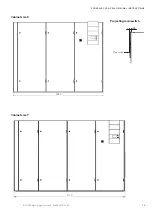
The position of the condensate drain is marked in the following
schemes for the pipe entrance areas.
The condensate drain is designed in the shape of a loop which
complies with the function of a syphon.
The internal diameter of the condensate drain tube is 25 mm.
View from behind

