2-0 Desk Operation
2.2.5
Area 4 – Vistonics™
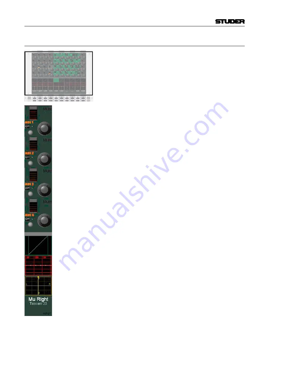
Vistonics™ Rotary Area
Each rotary control is grouped with a key to form a control element.
These control elements are sometimes used in a channel-related manner,
dedicating four control elements to each channel strip; sometimes, neigh-
boring channels are used in order to show a complete parameter set of
one single channel. This is the case when touching any graphical dis-
play of EQ, dynamics, or pan, but also when activating
VIEW: MISC
or
VIEW: CHANNEL
.
Vistonics™ Touch Screen Area
Graphical indication of dynamics, equalizer and pan. Touching the graphics
will open up all corresponding parameters on the rotary control area.
This section is also able to display bus assignment. Two modes are available:
Bus assignment as a ‘bubble view’ to give an overview over the whole console,
or bus assignment of a specific channel (one per bay).
The graphical pan display may vary depending on the configured panning
function or format. (2-CH Stereo Pan, Multi-format Pan, VSP).
Generic Display Area
The following information is continuously displayed:
• Inherited label (top line). This corresponds to the USER label of the con-
nected source (can be edited in the GC’s Global Patch window).
• Switchable label (second line). Normally this is set to USER labels, but
might be changed by pressing
GLOBAL VIEW: LABEL TYPE
. If set to
USER label, the device label of the connected source is being displayed
(e.g. ‘Mic1, StA’).
• Indication of channel type by color coding of the lower half as well as
writing the type in the bottom right corner.
The following information pops up when appropriate:
• Fader value in dB when touched (or ‘held’ when in dynamic automation
mode)
• Graphical representation of fader values in automation mode (replay
value of last mix pass and currently set value at the same time)
• Graphical representation of current setting and previewed snapshot at the
same time.
• Automation mode of the fader.
• Indication whether the fader was dynamically automated while pressing
AUTOMATION VIEW
.
• Numerical indication of the current peak meter value if metering is in
PEAK: HOLD CONT
mode, or of the overload value if
OVERLOAD: HOLD
is active.
•
N–1 indication and bus number.
Touching the upper half (for input channels, multi-track input channels, multi-
track monitor channels): Opens the GC’s General Patch window, showing the
channel input
position of the selected channel..
Touching the lower half (for all channels): Opens the GC’s General Patch
window, showing the
direct output
position of the selected channel.
Vista 9 Digital Mixing System
Date printed: 27.0.0
SW V4.5
Summary of Contents for Vista 9
Page 18: ...Vista 9 Digital Mixing System 1 Introduction Date printed 26 10 10 SW V4 5...
Page 42: ...2 Desk Operation Vista 9 Digital Mixing System Date printed 27 10 10 SW V4 5...
Page 90: ...Vista 9 Digital Mixing System 3 Parameters Date printed 27 10 10 SW V4 5...
Page 140: ...Vista 9 Digital Mixing System 3 52 Parameters Date printed 27 10 10 SW V4 5...
Page 298: ...Vista 9 Digital Mixing System 5 AutoTouch Date printed 28 10 10 SW V4 5...
Page 460: ...Vista 9 Digital Mixing System 6 Session Configuration Date printed 28 10 10 SW V4 5...
Page 506: ...Vista 9 Digital Mixing System 7 DAW Control Date printed 29 10 10 SW V4 5...
Page 513: ...Vista 9 Digital Mixing System DAW Control 7 Date printed 29 10 10 SW V4 5...
Page 517: ...Vista 9 Digital Mixing System DAW Control 7 13 Date printed 29 10 10 SW V4 5...
Page 524: ...Vista 9 Digital Mixing System 8 RELINK Date printed 29 10 10 SW V4 5...
Page 542: ...Vista 9 Digital Mixing System 8 20 RELINK Date printed 29 10 10 SW V4 5...
Page 546: ...SCore Live SCore Live Date printed 28 10 10...
Page 568: ...SCore Live 24 SCore Live Date printed 28 10 10...
Page 570: ...Vista Digital Mixing System 10 Application Notes Update Date printed 28 10 10 SW V4 5...


