background image

EN-41

DRAFT

SN

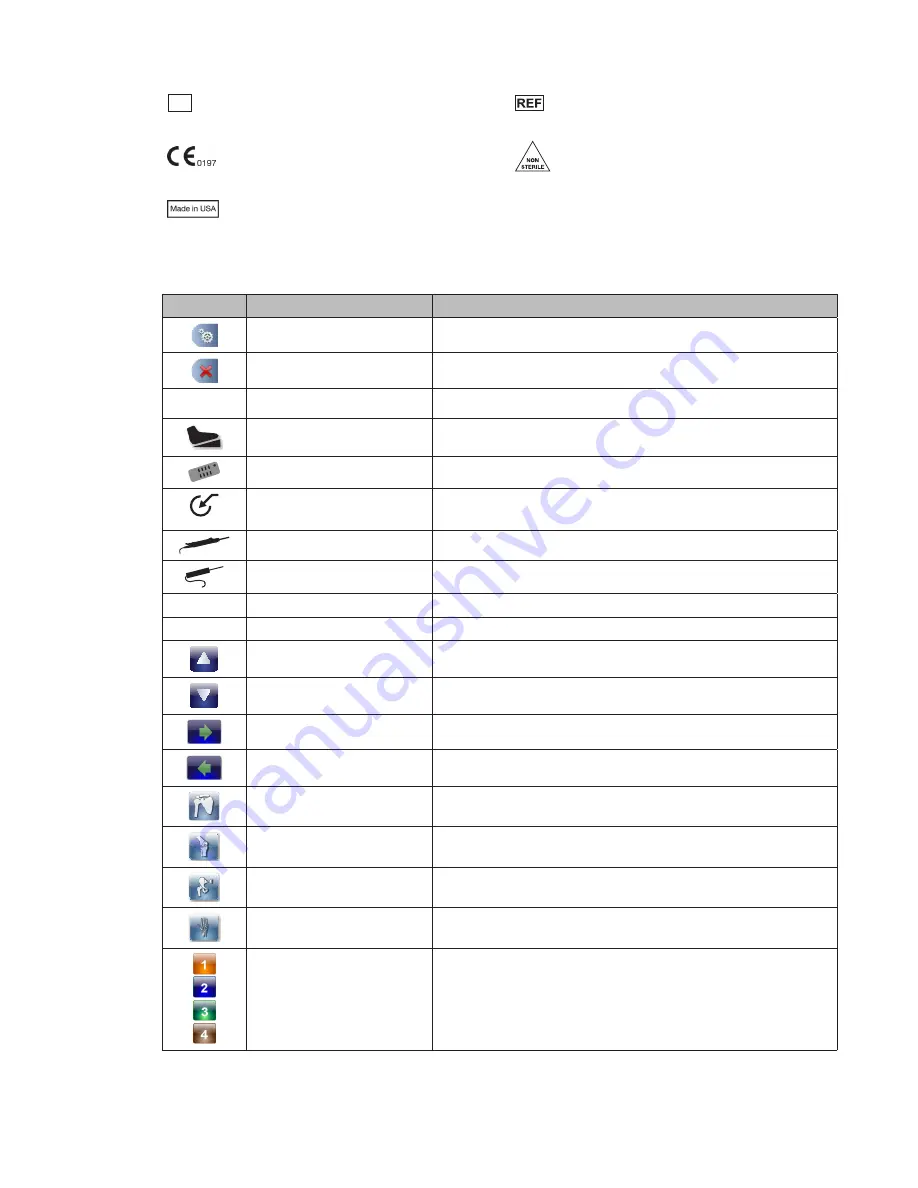
Serial Number


Catalog number

Fulfills requirements of the European Medical 
Device Directive 93/42/EEC

Non-Sterile

Made in USA

Interface

Icon

Name/Term

Description

OPEN MAIN MENU

Accesses the Main Menu

CLOSE MAIN MENU

Closes the Main Menu

XF

CROSSFIRE

Indicates the Crossfire is attached

FOOTSWITCH

Indicates the footswitch is attached

HAND CONTROL

Indicates the hand control is attached

AUXILIARY DEVICE

Indicates the auxiliary device is attached  
(currently there are no approved auxiliary devices for use)

SHAVER

Indicates an approved resection shaver console is attached

RF PROBE

Indicates an approved resection RF console is attached

OUTFLOW

Indicates the Outflow Cassette is inserted

DAY-USE

DAY-USE CASSETTE

Indicates the Day-Use Cassette is inserted

UP

Scrolls up

DOWN

Scrolls down

FORWARD

Advances to the next screen

BACK

Returns to the previous screen

SHOULDER JOINT

Selects the shoulder joint

KNEE JOINT

Selects the knee joint

HIP JOINT

Selects the hip joint

SMALL JOINT

Selects the small joint

HARDWARE COMBINATION 
SELECTION

Hardware combination selection (3 and 4 are only available if 
the hip joint is selected)

Summary of Contents for CrossFlow

Page 1: ...DRAFT 0450000000 CrossFlow Integrated Arthroscopy Pump DRAFT ...

Page 2: ...DRAFT ...

Page 3: ...re 18 Menu Features 20 Opening and Closing the Main Menu 20 Programming the Wash and Clear Functions Settings 20 Programming the Resection Integration Settings 21 Programming the Footswitch and Formula Shaver Settings 22 Loading User Preference Files 24 Navigating to the Settings Menu 25 Navigating to the Help Menu 27 System Feedback 27 Audible Feedback 27 Error Messages 27 Troubleshooting 29 Clea...

Page 4: ...EN 2 DRAFT Electromagnetic Compatibility 37 Regulatory Information 38 Symbols and Terminology 40 ...

Page 5: ...tion provided in the Electromagnetic Compatibility section of this manual 4 If the pump is installed with other equipment in a stacked configuration observe the pump to verify normal operation 5 Portable and mobile RF communications equipment may interrupt system operation When the pump is in use the conducted and radiated electrical fields may interfere with other electrical medical equipment If ...

Page 6: ...Do not use glass containers as they might implode due to the vacuum being generated inside of the container 7 Do not use this system in the presence of oxidizing agents or flammable materials e g anaesthetics gases fluids skin prepping agents and tinctures Observe appropriate fire precautions at all times 8 Keep the pump dry If liquid has accidentally leaked into the pump from the cassette s chang...

Page 7: ...ed 4 Stryker does not accept any liability for direct or consequential damages if the pump or the accessories are used improperly the instructions and rules in the manual are not followed the pump or the accessories are improperly connected and maintained non authorized persons perform repairs adjustments or alterations to the pump or accessories non authorized persons open the pump the prescribed...

Page 8: ...tandard irrigation fluids suction connectors and waste management systems The user may elect to employ one of two modes of operation Inflow Only Mode utilizes only the inflow function of the pump via the Inflow Cassette Tubing or the Day Use Inflow Cassette Patient Use Tubing Inflow Cassette Tubing The Inflow Cassette Tubing transmits fluid from saline bags to the inflow cannula at the surgical si...

Page 9: ...d return policy Part Numbers and Available Accessories The CrossFlow Integrated Arthroscopy Pump is featured in this manual Refer to individual manuals for all other products and accessories Part Number Description 0350220000 Autoclavable Hand Control 0450000000 CrossFlow Integrated Arthroscopy Pump 0450000100 CrossFlow Inflow Cassette Tubing 0450000110 CrossFlow Day Use Inflow Cassette Tubing 045...

Page 10: ...FLOW This device complies with part 15 of the FCC Rules Operation is subject to the following two conditions 1 This device may not cause harmful interference and 2 this device must accept any interference received including interference that may cause undesired operation IC 4919C XFLOW 1 Speaker 2 Power Outlet for Approved Resection RF Console 3 Power Outlet for Approved Resection Shaver Console 4...

Page 11: ...obile communications equipment may affect the normal function of the CrossFlow pump When placing the pump follow the instructions located in the Electromagnetic Compatibililty section of this manual 2 Connect the AC power Connect the provided hospital power cord to the AC inlet on the rear console panel Connect the other end to a hospital grade power outlet Warning Check the device label on the re...

Page 12: ...e rear panel of the CrossFlow pump as marked Using a 1 Phillips screwdriver attach and secure the power cord bracket Note The pump s screen will display the specific components that are connected when the device is powered on Warning When the CrossFlow pump is interconnected with other electrical devices leakage currents may be additive resulting in electromagnetic emissions that can interfere wit...

Page 13: ...he device is powered on Caution Do not connect an ethernet cable to the auxiliary port Turn the connector of the hand control and footswitch so that the red dot points up Do not thread or twist the cable connector for insertion or removal It is a push pull connector and may be damaged by twisting it into or out of place 5 For tubing connection instructions refer to the CrossFlow Inflow and Outflow...

Page 14: ... Pump Power the Pump On and Off 1 Press located at the bottom left corner of the front panel to power on the pump When this button is illuminated by a green LED the system is powered on The pump will display a splash screen while the software is loading 2 To power off the system press again Insert the Inflow Outflow Cassette Warning The choice of irrigation fluid should be determined by the physic...

Page 15: ... appear on the cassette if it is inserted before the Inflow Cassette depicted in this scenario 3 Connect the tubing For the Inflow and Outflow Cassette Tubing refer to the instructions in the CrossFlow Inflow and Outflow Cassette Tubing manual For the Day Use Inflow Cassette and Patient Use Tubing refer to the instructions in the CrossFlow Day Use Inflow Cassette and Patient Use Tubing manual Sele...

Page 16: ...ee Press to select the hip Press to select the small joint 2 When the desired joint is highlighted the screen will advance to the next screen Note Press to return to the user preference file selection screen Prime the Inflow Tubing and Operate the Pump Warning Start the pump with the inflow tubing outside of the joint all of the inflow tubing clamps open and no hardware attached Failure to remove ...

Page 17: ...g application areas Joint Default Settings Knee 45 mmHg Shoulder 50 mmHg Hip 50 mmHg Small 35 mmHg Note Default pressure settings are only suggestions and each procedure and each patient may require different parameters Select the optimal pressure based on the patient profile including but not limited to blood pressure height weight age and tissue quality 1 If necessary press and to increase or de...

Page 18: ...elect the following default hardware combination if Standard Settings is selected Hardware option Joint Default combination Knee Stryker 5 8 mm x 140 mm cannula with 4 0 mm scope Shoulder Stryker 5 8 mm x 140 mm cannula with 4 0 mm scope Hip Stryker 5 0 mm x 165 mm cannula bridge with 4 0 mm scope Small Stryker 4 0 mm x 75 mm cannula with 2 7 mm scope None Alternate hardware combination selections...

Page 19: ...nly enabled if the hip joint is selected 7 Repeat steps 3 and 4 to select the scope cannula combination for options and or In this scenario 4 0 x 120 mm cannula with 2 7 mm scope is highlighted for option 8 When the desired hardware combinations are highlighted press to confirm the selections and advance to the Run screen Swapping Between Hardware Combination Selections During the Case The Hot Swa...

Page 20: ...rm the Wash function Follow the instructions in the Program the Wash and Clear Function Settings section to adjust the default settings 2 Press to repeat or stop the Wash function Performing the Drain Function The Drain function is only available in the Inflow Outflow mode It operates the outflow pump to remove fluid from the surgical site for 30 seconds or until the user stops the pump 1 Press to...

Page 21: ...w Cassette Tubing manual on instructions on how to disconnect and discard the tubing Always maintain a sterile technique 4 Press the Inflow Cassette Ejection button blue and or the Outflow Cassette Ejection button red on the front panel of the pump to eject the cassette s 5 Discard the cassettes and tubing appropriately ...

Page 22: ... will increase by 50 of the current setting and the flow limit will increase by 100 of the current setting for 30 seconds Inflow Outflow mode Increases set pressure and suction by user specified percentage over user specified duration By default the set pressure will increase by 50 of the current setting and the suction will increase by 100 of the current setting for 30 seconds Clear Inflow only m...

Page 23: ...100 for 30 seconds Clear Function Settings 1 Press to program the settings for the Clear function 2 Press and to adjust the Flow or Duration In this scenario the flow will increase by 100 for 30 seconds Programming the Resection Integration Settings Note Adjusting the settings will override the default and user preference file settings 1 Press to open the Main Menu 2 Press to open the Resection In...

Page 24: ...robe is selected 2 Press and to increase or decrease the Suction adjust in increments of 10 from 0 100 In this scenario the Suction is set at 50 Programming the Footswitch and Formula Shaver Settings 1 Press to open the Main Menu 2 Press to open the Footswitch Formula Shaver Settings Menu Setting Function Wash Inflow only mode Increases set pressure and flow limit by user specified percentage over...

Page 25: ... to select its function 3 Press and to scroll up and down the function list 4 Press the function of choice to assign the function to the pedal In this scenario the Wash function is selected 5 Repeat steps 2 4 to program the red foot pedal iSwitch Footswitch 1 Press the iSwitch icon to program settings for the iSwitch Footswitch 2 Press the appropriate button pedal highlighted with green border to ...

Page 26: ...nario the Wash function is selected for Button I Formula Shaver 1 Press the Formula icon to program settings for the hand control 2 Select a button in the left hand menu to program it In this scenario Button III is selected Note Only one button or pedal may be assigned a function 3 Press and to scroll up and down the function list 4 Press the function of choice to assign the function to the button...

Page 27: ...the USB drive to from the pump 6 Press below the USB or pump list to delete the selected file 7 To delete the selected file press To cancel the operation press Transferring Files to the Crossfire System 1 Press to transfer a user preference file to the Crossfire system 2 Press and to scroll up and down the file list 3 Select the file to transfer Note Only preference files containing Crossfire sett...

Page 28: ...rs in the box In this scenario version 00 02 10 is installed Press to upgrade the software The system will automatically restart once the software is succesfully upgraded Adjusting the Actual Pressure Display 1 Press to open the Actual Pressure Display selection menu 2 Select the desired display icon The selection will be highlighted with a green box Accessing the Stryker Settings Menu For Stryker...

Page 29: ...hould be carefully reviewed Caution Visual popup error is displayed for five seconds user may clear the message when the problem is resolved Fault The pump will stop user may clear the message when the problem is resolved Lockdown The pump will stop reboot system Error Message Cause Possible Solution CAUTION Cassette about to expire two hours left before expiration Replace the cassette CAUTION Pre...

Page 30: ...is specified in the user preference file but it is improperly or not connected to the pump Ensure the console is properly connected to the pump Follow the instructions in the Setup and Device Configuration section in this manual Reboot the system If the problem persists contact your Stryker representative or return the console for repair LOCKDOWN Hardware fault detected Reboot the system If the pr...

Page 31: ...ses if they are out of service The pump is plugged in the fuses are functional and or have been replaced and the pump still does not turn on A hardware error occurred Plug the pump in to a different main outlet If the problem persists contact your Stryker representative The cassette s are inserted but the Run Screen does not appear and the pump does not start The Inflow or Outflow RFID tag cannot ...

Page 32: ... hardware from the tubing and repeat the priming step If the problem persists replace the cassette The suction level is set too high Decrease the suction level The pump cannot achieve the set pressure There is a hardware setup error the flow limit is set too low or the suction level is set too high Verify the luer lock is tightly closed the correct hardware is selected and properly connected and t...

Page 33: ... the console for repair A hardware or software error occurred A user preference file was accidentally deleted from the pump Unintentional deletion of a user preference file Transfer the user preference file from a USB drive to the pump according to the instructions in the Transfer Files to from a USB drive section of this manual The pump is stopped but the Outflow Cassette is stuck and cannot be e...

Page 34: ...leaning the front LCD screen Excess liquid or drips that enter the bottom of the screen may result in product damage Footswitch Warning Clean the footswitch prior to first use and after every subsequent use Consult the footswitch manual P17862 for cleaning instructions Hand control Warning Clean and sterilize the hand control prior to first use and after every subsequent use to minimize risk of in...

Page 35: ...pump according to the instructions in Power the CrossFlow Pump On and Off section of this manual The power button will be illuminated by a green LED indicating the system has powered on 2 Stepper motor Insert the cassettes according to the instructions in Insert the Inflow Outflow Cassette section of this manual Visually inspect the stepper motors located in the cassette holder they will be diseng...

Page 36: ...umn height h indicated in the table below Ensure the tubing in the water column is completely filled with fluid Read the actual pressure displayed on the pump The test has been successfully completed if the actual pressure on the pump is within the range indicated in the table below for a given height of the water column Height of water column h Acceptable actual pressure mmHg Inches Centimeters 1...

Page 37: ...rough the current maintenance period a Service Pump Soon notification will appear on the screen An authorized Stryker service technician must inspect and service the device according to the maintenance and calibration schedule below to maintain product functionality Component Maintenance Calibration Period Motors 2 years Pinch valves 2 years Pressure transducer 2 years Expected Life Equipment Expe...

Page 38: ...tion Environmental Specifications Operating Temperature 5 40 C Operating Humidity 30 95 RH non condensing Shipping Temperature 18 60 C Shipping Humidity 15 90 RH Safety and EMC Compliance UL 60601 1 2006 IEC 60601 1 2 2007 IEC 60601 1 4 2000 IEC 60601 1 6 2010 IEC 60601 1 8 2006 IEC 62304 2006 IEC 62366 2007 CAN CSA C 22 2 No 601 1 M90 2003 CAN CSA 22 2 No 60601 1 2002 AS NZS 3200 1 0 1998 IEC 606...

Page 39: ...ts other than domestic and those directly connected to the public low voltage power supply network that supplies buildings used for domestic purposes Harmonic emissions IEC61000 3 2 Not applicable Voltage Fluctuations flicker emissions IEC61000 3 3 Not applicable Guidance and Manufacturer s Declaration Electromagnetic Immunity CROSSFLOW INTEGRATED ARTHROSCOPY PUMP is intended for use in the electr...

Page 40: ...verify normal operation If abnormal performance is observed additional measures may be necessary such as reorienting or relocating the CROSSFLOW INTEGRATED ARTHROSCOPY PUMP unit b Over the frequency range 150 kHz to 80 MHz field strengths should be less than 3 V m Recommended Separation Distances Between Portable and Mobile RF Communications Equipment and the CROSSFLOW INTEGRATED ARTHROSCOPY PUMP ...

Page 41: ...representative Stryker France ZAC Satolas Green Pusignan Av de Satolas Green 69881 MEYZIEU Cedex France Declare under our sole responsibility that the product Product Name CrossFlow Integrated Arthroscopy Pump Trade Name CrossFlow Integrated Arthroscopy Pump Type or Model 0450000000 Relevant Supplementary Information None to which this declaration relates is in conformity with the essential requir...

Page 42: ...ential ground plug connects to potential equalization conductor The resulting medical electrical system shall follow all applicable IEC 60601 1 requirements Stryker Firewire enables firewire connection with Stryker firewire devices Crossfire iSwitch SDC3 Fuse rating Type BF Applied Part Probe Shaver Alternating Current RoHS 50 years IPX1 Protection against vertically falling objects Follow instruc...

Page 43: ...ently there are no approved auxiliary devices for use SHAVER Indicates an approved resection shaver console is attached RF PROBE Indicates an approved resection RF console is attached OUTFLOW Indicates the Outflow Cassette is inserted DAY USE DAY USE CASSETTE Indicates the Day Use Cassette is inserted UP Scrolls up DOWN Scrolls down FORWARD Advances to the next screen BACK Returns to the previous ...

Page 44: ... file CANCEL Rejects an action CONFIRM Accepts an action HELP Accesses task oriented help related to screen and button functionality WASH MENU Navigates to the Wash menu to adjust the Wash and Clear function settings CLEAR FUNCTION Increases the flow limit by a user specified percentage over a user specified duration for Inflow only mode Increases the suction by a user specified percentage over a ...

Page 45: ...to the Settings screens GENERAL SETTINGS Adjusts the volume brightness and language VOLUME Adjusts the volume of pump BRIGHTNESS Adjusts the monitor brightness SOFTWARE UPGRADE Loads new software upgrades from a USB drive ACTUAL PRESSURE DISPLAY ICON SELECTION Selects the Actual Pressure Display icon STRYKER SETTINGS Password protected settings for Stryker use only FLOW The fluid entering and exit...

Page 46: ...EN 44 DRAFT ...

Page 47: ...DRAFT ...

Page 48: ...Stryker France ZAC Satolas Green Pusignan Av De Satolas Green 69881 MEYZIEU Cedex France Stryker Corporation or its divisions or other corporate affiliated entities own use or have applied for the following trademarks or service marks CrossFlow and the Stryker logo All other trademarks are trademarks of their respective owners or holders P17330 A 2012 06 ...

Reviews: