47
I N S T A L L A T I O N
E N
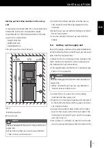
Setting up the milling machine on the set-up
cart
A clearance of at least 200 mm is to be observed
sidewards, to the rear and upwards. Space
requirements for the milling machine on the set-
up cart incl. connections:
_
Height: 1591 mm
_
Width: 970 mm
_
Depth: 860 mm
The set-up surface must be level.
Fig. 5
1
Milling machine
2
Set-up cart
▷
Position the milling machine onto the set-up
cart, ensuring that the legs engage into the
retainers.
▷
Move the set-up cart with the milling machine to
the set-up location.
▷
Lock the casters of the set-up cart with the
brakes.
5.2
Setting -up the supply unit
Set up the supply unit below the work table/bench
of the milling machine or into the set-up cart avail-
able from the manufacturer.
In order for the C/L drain pipe to be mounted, the
table must be set up with a certain clearance to
the wall (see set-up instructions).
▷
Fill coolant/lubricant into the C/L container (see
section 7.5 on page 61).
▷
Connect the C/L supply line to the milling
machine and the supply unit.
▷
Plug the C/L drain pipe together and connect it
to the milling machine and the supply unit (see
set-up instructions).
▷
Connect the control cable to the control inter-
face for the supply unit on the rear side of the
milling machine ([9] in Fig. 2) and to the supply
unit ([4] in Fig. 3).
▷
Set up the C/L container or insert it into the set-
up cart, as required (please refer to section 7.6).
NOTE:
Possible damage of the electric lines and the C/L
supply line:
▷
When moving the set-up cart, pay attention
that no lines are driven over.
≥ 200
570
≥ 200
≥1591
1391
1
2
NOTE:
Possible damage of the electric lines and the C/L
supply line:
▷
When moving the set-up cart, pay attention
that no lines are driven over.


