49
I N S T A L L A T I O N
E N
Requirements on air purity for the Jäger
spindle
When another service unit than the one supplied is
to be used, the following connection conditions
according to DIN-ISO 8573-1 must be ensured:
_
Solid contaminants: Class 3
(particle size max. 5
μ
m, particle density max.
5 mg/m
3
)
_
Water content: Class 4
(max. pressure dew point +3
°C
, water content
max. 6000 mg/m
3
)
_
Total oil content: Class 2;
(max. oil content 0.1 mg/m
3
)
Recommended extraction system require-
ments
When another extraction system is to be used, it
must meet the following requirements:
_
Suction capacity: 240 m
3
/h
_
Suitability for zirconium-oxide dusts
_
HEPA microfilter (97.97 %), filter class H12,
dust category M
The connection of the extraction hose to the
machine is made with an adapter (in delivery
scope). The adapter fits extraction hoses with a
38 mm interior diameter.
Installation of the extraction system in the
supply unit
▷
Set the extraction system to the operating
mode AUTO.
▷
Insert the extraction system with the extraction
opening facing toward the rear onto the set-up
cart.
▷
Plug in the control cable of the extraction sys-
tem at the rear side of the milling machine.
▷
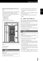
Insert the extraction hose of the extraction sys-
tem into the milling machine.
5.4
Installation of the CAM and milling
machine software
▷
Insert the CAM software CD-ROM into the drive
of the PC.
The software to be installed is on the CD.
▷
Execute the
“
.exe
”
file and follow the directions
on the monitor.
Connecting the interfaces
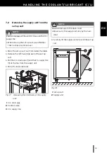
Fig. 7
Interfaces on the rear side of the milling
machine
1
Slot for SD memory card
2
Ethernet interface
3
USB data port
4
Control interface for extraction
5
Main switch
6
Power supply connection
▷
Make sure that the main switch [6] of the milling
machine is in the 0 position.
▷
Check if the SD memory card is properly seated
in the slot [1] on the rear side of the milling
machine.
▷
Connect the mains cable to power supply con-
nection [7] of the milling machine as well as to a
mains socket outlet.
5
I
0
230V
100/115V
T3.15 A
T6.30 A
100/115/230VAC
6
1 2 3
4


