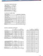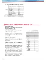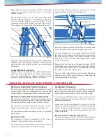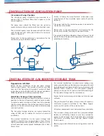
Number of Collectors
2
3
DN 15 pipes
40m
30m
Table 13
Water Supply
Approved pressure limiting valves rated at 500kPa are
required if the mains water supply pressure exceeds
500kPa.
The gas booster will not achieve the maximum rated flow
if the mains water supply pressure is below the minimum
supply pressure specified for the gas booster in Table 7
“Gas Boosters Specifications”. The system will operate at
lower pressures but will deliver hot water at lower flow
rates.
Water chemistry and impurity limits are specified under
“Water Quality” in the “Important Information” section
of these instructions. Metropolitan water supplies
generally meet these requirements. Please contact the
relevant water supply authority or have the water tested
if uncertain about the water supply quality.
If necessary, a suitable filter or water softener should be
fitted in the mains water supply to achieve the required
water quality.
For locations with high sediment levels in the water
supply, the hot water storage tank should be flushed at
regular intervals. Stratco recommend that a drain cock
is fitted at the cold water inlet to the hot water storage
tank.
Water Pipes, Valves & Fittings
All hot water pipes must be insulated with thermal
lagging such as Polyethylene foam to reduce heat loss
and maximise performance of the solar hot water heating
system.
All pipe sizes should conform to AS/NZS 3500 except
collector flow and return pipes.
Solar collector flow and return pipes should be 15mm
copper tube to withstand the high pressures and
temperatures that occur. Maximum recommended total
lengths for the cold water flow and hot water return
pipes are shown in Table 13.
The pressure and temperature relief (P&TR) valve is a
safety device and must be fitted to the hot water storage
tank. The P&TR valve supplied is rated at 10.0kW,
which must exceed the thermal load applied to the hot
water storage tank. For gas boosted solar hot water
heater systems, the thermal load is applied by the solar
collectors only. The gas booster does not apply thermal
load to the hot water storage tank.
A cold water expansion control valve (ECV) rated at
700kPa must be fitted to the cold water supply of the hot
water storage tank. This will reduce hot water discharge
resulting in wear of the P&TR valve.
Approved pressure limiting valves rated at 500kPa must
be fitted if the mains water supply pressure exceeds
500kPa.
A combination non-return/isolating valve and strainer is
fitted to the cold water supply of the hot water storage
tank.
Gas boosters for Stratco Solarcore
TM
hot water heating
systems are preset to deliver hot water at 70°C in
accordance with plumbing regulations. A temperature
limiting device, such as thermostatic mixing or tempering
valves, must be fitted to limit the hot water temperature
For vitreous enamel hot water storage tanks, allow a
clearance of one cylinder height above the hot water
storage tank to allow inspection and replacement of the
sacrificial anode.
Gas Booster Location
The gas booster is designed for outdoor installation only,
and must be located in a position where wind and natural
convection will disperse gas leakage and combustion
products.
The gas booster must be mounted on a vertical surface
with the water and gas connections underneath. In most
installations the gas booster is mounted directly on the
hot water storage tank.
If the gas booster is not mounted on the hot water
storage tank, ensure that the wall or structure on which
it will be mounted is capable of supporting the weight
of the gas booster and associated plumbing. The weight
of the gas booster models is specified in Table 7 “Gas
Boosters Specifications”.
The location of the gas booster terminal flue must be in
accordance with AS 5601 Figure 5.3.
Refer to AS 5601 for specific requirements in relation to
gas boosters installed on elevated structures or under
floors.
The gas booster will require a gas supply as outlined
in the “Gas Supply” section of these instructions and a
240V, 10A earthed weather proof power point.
Gas Supply
The gas meter and regulator must be rated for the
maximum flow of the gas booster in addition to all
other gas appliances on the premises. Please refer to
the manufacturer’s instructions for the gas booster to
determine maximum gas consumption and required gas
pressure.
It is the installers responsibility to ensure gas meter,
regulator and pipework are functional, sized correctly
and rectify as necessary.
Gas pipe sizing must conform to the sizing chart in AS
5601. If pipe sizes are not sufficient, the gas booster will
not achieve full heating performance.
An approved full flow isolation valve and disconnection
union must be fitted to the gas inlet of the gas booster.

