SPX TG H15-50 Instruction Manual Download Page 54

54

A.0500.351 – IM-TGH/07.02 EN (10/2015)
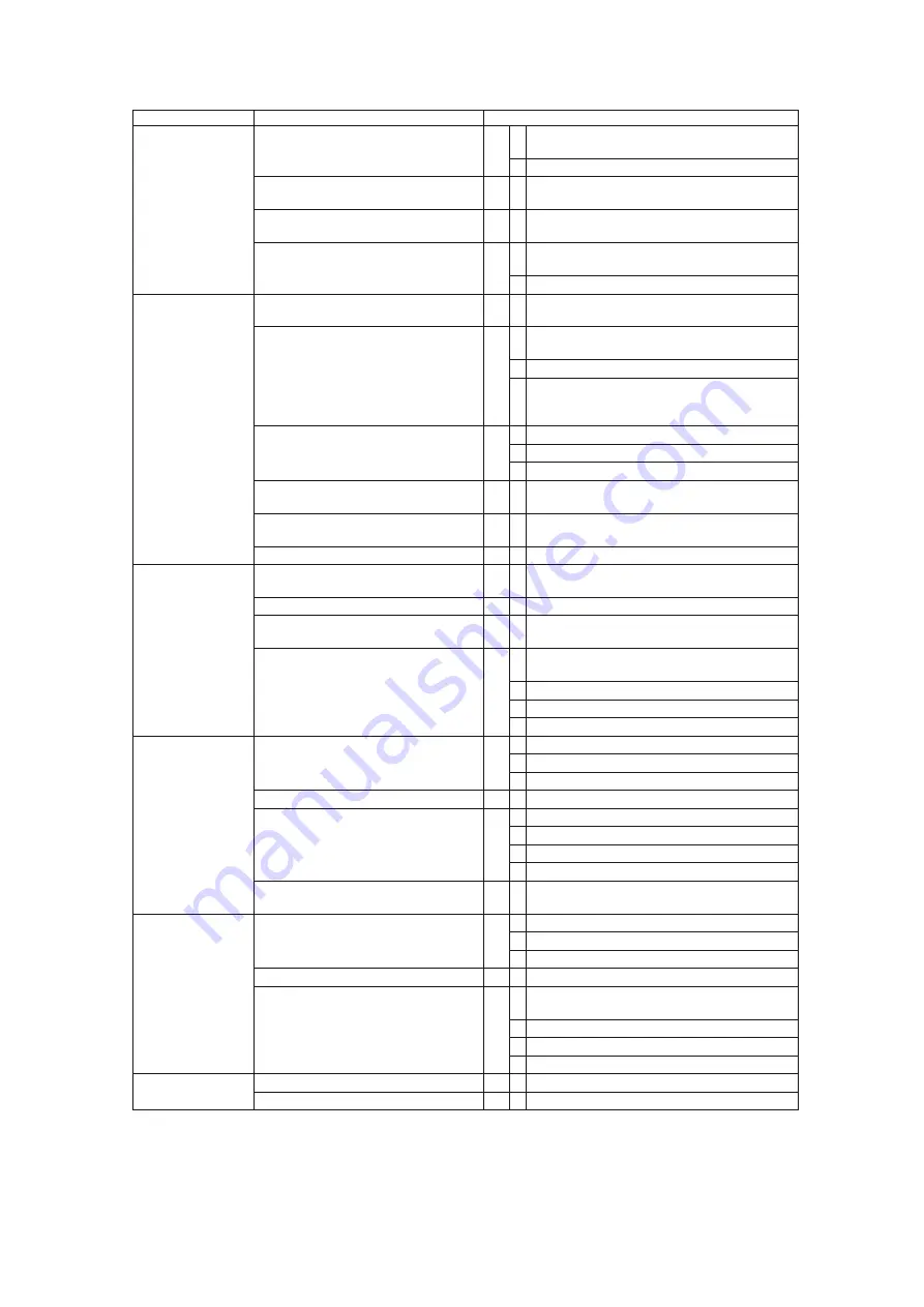
Symptom

Cause

Remedy

Not enough capacity Viscosity too low

17 • Increase pump speed. 

Attention! 

Do not exceed 

maximum speed and check NPSHr.

• If necessary, install a larger pump.

• If pump is heated by means of heating jackets or 

electrical heating, reduce the heating input.

Axial clearance

18  • Check axial clearance and correct. 

See section 3.21 Maintenance instructions.

Gases come free

19 • Increase pump speed. 

Attention! 

Do not exceed 

maximum speed and check NPSHr.

• Install a larger pump

Pump too noisy

Pump speed too high

20 • Reduce pump speed.  

If necessary, install a larger pump.

Cavitation

21 • Reduce difference between pump and suction 

tank level.

• Increase suction pipe diameter.
• Reduce length and simplify suction pipe (use as 

few elbows and other fittings as possible). 
Also see section 3.18 Installation.

Back pressure too high

22 • Increase pipe diameter.

• Reduce working pressure.
• Check accessories (filter, heat exchanger, etc.).

Coupling misalignment

23 •  Check and correct alignment. 

Also see section 3.18 Installation.

Vibration of base plate or pipings

24 • Make base plate heavier and/or fix base plate/

pipe work better.

Ball bearings damaged or worn

25 •  Replace ball bearings.

Pump consumes 
too much power or 
becomes hot

Pump speed too high

26 •  Reduce pump speed.  

If necessary, install a larger pump.

Gland packing too tight

27 • Check or replace gland packing.

Coupling misalignment

28 • Check and correct alignment.

Also see section 3.18 Installation.

Viscosity too high

29 • Increase axial clearance. 

See section 3.21 Maintenance instructions.

• Heat pump.
• Reduce pump speed.
• Increase discharge pipe diameter.

Rapid wear

Back pressure too high

30 • Increase pipe diameter.

• Reduce working pressure.
• Check accessories (filter, heat exchanger, etc.) 

Solid matter in liquid

31 • Filter liquid.

Pump runs dry

32 • Correct liquid supply.

• Provide level switch or dry running protection.
• Heat up liquid.
• Stop or reduce air sucking.

Corrosion

33 •  Change pump materials or application  

parameters.

Motor overloading

Back pressure too high

34 • Increase pipe diameter.

• Reduce working pressure.
• Check accessories (filter, heat exchanger, etc.).

Gland packing too tight

35 • Check and replace gland packing.

Viscosity too high

36 • Increase axial clearance. 

See section 3.21 Maintenance instructions.

• Heat pump.
• Reduce pump speed.
• Increase discharge pipe diameter.

Pump leak

Gland packing leaks excessively

37 • Check or replace gland packing.

Mechanical seal leaks

38 • Replace mechanical seal.

Summary of Contents for TG H15-50

Page 1: ...I M TG H 07 02 E N 10 2015 TopGear H I NTE R NAL G EAR PU M PS OR IG I NAL I N STR UCTION S R EAD AN D U N D E R STAN D TH I S MAN UAL PR IOR TO OPE RATI NG OR S E RVICI NG TH I S PROD UCT I N STR UCT...

Page 2: ...ssembly with drive are in conformity with the relevant provisions of the Machinery Directive 2006 42 EC Annex I Manufacturer Declaration Machinery Directive 2006 42 EC Annex IIB The partly completed p...

Page 3: ...________________________________ 17 Maximum viscosity________________________________________________ 17 3 6 Pressure__________________________________________________ 18 3 7 Sound level _____________...

Page 4: ..._______________________40 3 18 7 1 Drain lines______________________________________________ 40 3 18 7 2 Heating jackets__________________________________________ 41 3 18 8 Flush quench media ________...

Page 5: ...ed connections__________________________63 3 21 7 1 Threaded connection Rp example Rp 1 2 ___________________ 63 3 21 7 2 Threaded connection G example G 1 2 _____________________ 63 4 0 Instructions...

Page 6: ...____________ 88 5 2 5 Shaft seal options__________________________________________89 5 2 5 1 Packing rings PQ with lantern ring _______________________________________________________ 89 5 2 5 2 Packi...

Page 7: ...The manual must be kept easily accessible to the operator Important The pump must not be used for other purposes than recommended and quoted for without consulting your local supplier Liquids not suit...

Page 8: ...hat can cause overheating short circuits corrosion damage and fire must be kept away from motors and other exposed equipment If the pump handles liquids hazardous for person or environment some sort o...

Page 9: ...injury The pump unit must be mounted on a level surface and either be bolted to the foundation or be fitted with rubber clad feet The pipe connections to the pump must be stress free mounted securely...

Page 10: ...he users and operator from fastening and injuring themselves on the rotating shaft shaft coupling The pump unit is supplied with factory mounted guards with certified maximum gaps in accordance with s...

Page 11: ...ead is the total absolute inlet pressure at the pump suction connection minus the vapour pressure of the pumped liquid NPSHa is expressed in meter liquid column It is the responsibility of the user to...

Page 12: ...The pump properties are encoded in the following type indication which is to be found on the nameplate Example 1 Pump family name TG TopGear 2 Pump range name H High demanding applications 3 Hydraulic...

Page 13: ...shaft materials S Bush in hardened steel C Bush in carbon H Bush in ceramic U Bush in hard metal B Bush in bronze 12 Rotor and shaft materials G2 Rotor in iron and shaft in hardened steel G5 Rotor in...

Page 14: ...orocarbon GS WT Single mechanical seal Burgmann M7N SiC SiC PTFE FFKM Remark EPDM and FFKM Chemraz O ring sets available on request Single mechanical seal option without mechanical seal GS XX Single s...

Page 15: ...he rotor and idler gear unmesh an underpressure is created and the liquid enters the new created cavities Liquid is transported in sealed pockets to the discharge side The walls of the pump casing and...

Page 16: ...ief valve indicates that the installation is not functioning properly The pump must be shut down at once Find and solve the problem before restarting the pump When the safety relief valve is not insta...

Page 17: ...osity Remark Figures are for Newtonian liquids at operating temperature The maximum allowable viscosity between the sliding faces of the mechanical seal depends on nature of liquid Newtonian plastic e...

Page 18: ...h the pump casing is tested The test pressure is 1 5 times the design pressure Following figure gives a graphical presentation of the several kind of pressures 3 7 Sound level 3 7 1 Sound level of a p...

Page 19: ...L f L1 L2 3 0 2 5 2 0 1 7 1 4 1 2 1 0 Ltotal L1 L corrected where Ltotal the total sound level of the pump unit L1 the highest sound level L2 the lowest sound level Lcorrected term depending on the d...

Page 20: ...m at 10 bar gives a temperature of 180 C T jackets are designed for use with thermal oil and apply to the DIN4754 safety standard for thermal oil transfer This DIN standard specifies flange connection...

Page 21: ...re K hyd with viscosity mPa s shaft speed rpm diff pressure bar K hyd design constant for each pump size TG H pump size K hyd 2 32 6000 3 32 7500 6 40 5500 15 50 6250 23 65 4000 58 80 3750 86 100 3600...

Page 22: ...360 360 58 80 390 390 390 550 550 550 86 100 600 600 600 840 840 840 185 125 1300 1300 1300 1820 1820 1820 360 150 2000 2000 2000 2800 2800 2800 The nominal torque Mn has to be checked for the normal...

Page 23: ...2 or 3 The code 1 always stands for normal and no special action is considered The indicated numbers in the tables below are average values in microns m Radial clearance on rotor idler outside diamete...

Page 24: ...TG H 2 32 3 32 6 40 15 50 23 65 58 80 86 100 185 125 360 150 Minimum m 320 320 320 360 400 400 400 440 440 Maximum m 640 640 640 720 800 800 800 880 880 3 15 Maximum size of solid particles TG H 2 32...

Page 25: ...e graphite fibres without impregnation Low coefficient of friction and good dry running properties Used as wear resistant packing at high temperature Application temperature 60 C to 500 C Chemical res...

Page 26: ...hanical seal are lubricated by a barrier fluid under pressure which allows high viscous liquids to be pumped Second sealing box type GG and GD maximum temperature and pressure Maximum temperature of t...

Page 27: ...6 53 72 9 9 13 8 58 80 40 72 82 110 94 58 4xM8 56 90 6 12 15 12 86 100 45 77 87 120 104 63 4xM8 55 86 6 12 15 12 185 125 55 90 106 160 124 203 75 4xM8 58 117 6 14 16 16 360 150 65 105 120 170 142 180...

Page 28: ...tion the gland packing area can be filled with grease from the outside before the pump is actually started This prevents the chocolate from entering this area until the packing is properly adjusted Ot...

Page 29: ...tem This option can be used for medium temperatures up to 220 C and a maximum pressure of 16 bar Benefits Cartridge system easy to assemble Independent of sense of rotation Low friction and limited dr...

Page 30: ...lve size for TG H86 100 TG H185 125 60 Safety relief valve for TG H360 150 3 Materials G Safety relief valve in cast iron not for foodapplications S Safety relief valve in steel not for foodapplicatio...

Page 31: ...maximum working pressure The set pressure can be set lower on request never higher Working pressure class 4 6 10 16 Standard set pressure bar 5 7 11 17 Working pressure range bar 1 4 3 6 5 10 9 16 Set...

Page 32: ...5 4 5 60 1 72 0 58 16 25 5 4 5 60 1 72 0 58 15 50 23 65 4 37 0 4 5 93 0 21 4 76 6 37 0 4 5 93 0 21 4 76 10 36 5 6 0 90 0 81 1 23 16 36 5 6 0 90 0 81 1 23 58 80 Vertical 4 49 0 7 0 124 0 32 3 13 6 49...

Page 33: ...Single safety relief valve horizontal Pos Description V18 V27 V35 V50 V60 Preventive Overhaul 7010 Valve 1 1 1 1 1 7030 Valve casing 1 1 1 1 1 7040 Spring casing 1 1 1 1 1 7050 Cover 1 1 1 1 1 7100 S...

Page 34: ...ul 7041 Heated spring casing N A 1 1 1 1 Pos Description V18 V27 V35 V50 V60 Preventive Overhaul 8010 Y casing N A 1 1 1 1 8020 Cylindrical head screw 16 16 16 16 8030 Stud bolt 8 8 8 8 8040 Hexagonal...

Page 35: ...ng fluid connections is observed and kept legible 3 18 2 Location 3 18 2 1 Short suction line Locate the pump pumpunit as close as possible to the liquid source and if possible below the liquid supply...

Page 36: ...section 3 18 9 Guidelines for assembly and section 3 18 9 6 Shaft coupling Horizontal mounting Pumps are to be mounted horizontally on the integral feet Other kinds of installation have an influence o...

Page 37: ...ys viewed from the shaft end towards the pump Unless otherwise specified on the order TopGear pumps are built at the factory for clockwise rotation left figure above which we define as the standard di...

Page 38: ...he shaft rotation is correct in relation to the port position but different from the direction indicated by rotation arrow plate the safety relief valve must be disassembled and turned around by 180 I...

Page 39: ...lters and foot valve also cause pressure losses Diameters length of piping and other components should be selected in such a way that the pump will operate without causing mechanical damage to the pum...

Page 40: ...nk not to the suction port 3 18 6 3 Isolating valves To allow proper maintenance it is necessary to be able to isolate the pump Isolation can be done by installing valves in suction and discharge line...

Page 41: ...provided with threaded connections Bl see chapter 6 0 for the dimensions The connection can be done by threaded pipes or pipe connections with sealing in the thread conical thread applying ISO 7 1 or...

Page 42: ...n dangerous media max 10 bar max 200 C They are provided with threaded connections Bo see chapter 6 0 for dimensions The connection can be done with threaded pipes or pipe connections with sealing in...

Page 43: ...sh media 3 18 8 2 Single Mechanical seal To guarantee lubrication and cooling of the sliding faces let a media circulate along the mechanical seal Proceed as follows One connection point Connect sucti...

Page 44: ...This locking ring prevents the static part of the mechanical seal from being pushed out of its seat in case quench pressure B falls back or drops out This locking ring must be adapted to the static r...

Page 45: ...51 52 61 62 GD GCD 08 09 11 12 13 51 53 54 62 Examples API plan 02 ISO code 00 Circulation not provided but possible Connections are plugged and can be used for possible future venting of the shaft s...

Page 46: ...n and compatible with the fluid being pumped API plans 53 54 ISO codes 09 11 12 API plans 51 62 ISO codes 08 13 Circulating quench Non circulating quench API plan 61 ISO code 03 Leakage check and cont...

Page 47: ...8 9 1 Transport of pump unit Prior to lifting and transporting a pump unit make sure that the packaging is of sturdy enough construction is and will not be damaged during transport Use crane hooks in...

Page 48: ...e motor against overloads and short circuits a thermal or thermo magnetic circuit breaker must be incorporated Adjust the switch for the nominal current absorbed by the motor Connection Do not use a s...

Page 49: ...ling halves see figure 4 Repeat this check at operating temperature and spend time achieving minimum alignment deviation 5 Fit the protecting guard See the figure below and the corresponding table for...

Page 50: ...the pump should be cleaned thoroughly Proceed as described in section 3 21 2 8 Draining of fluid Remark pumps made for food applications are preserved with a food grade oil The oil used is a NSF H3 a...

Page 51: ...of safety relief valve corresponds with suction and discharge lines c Make sure a double safety relief valve is installed when the pump has to operate in two directions c The set pressure of the safe...

Page 52: ...acking for chocolate applications the packing needs to be tightened bit by bit at the initial start up in order to achieve the utmost minimum of leakage just enough to lubricate the packing rings Exce...

Page 53: ...k or replace shaft seal Check provide quench on shaft seal Connect plug Bb to the pump discharge in order to increase the pressure in the sealing box Cavitation 10 Reduce difference between pump and s...

Page 54: ...pipe work better Ball bearings damaged or worn 25 Replace ball bearings Pump consumes too much power or becomes hot Pump speed too high 26 Reduce pump speed If necessary install a larger pump Gland p...

Page 55: ...cal seal with hard seal faces and barrier liquid Note If symptoms persist the pump must be taken out of service immediately Contact your local supplier 3 20 1 Instructions for re using and disposal 3...

Page 56: ...ts have very small tolerances and or are vulnerable a clean work environment must be created during on site maintenance 3 21 2 2 Tools For maintenance and repairs use only technically appropriate tool...

Page 57: ...rical devices Replace defective fuses only with original fuses of the prescribed capacity After each maintenance session check the components of the electrical installation for visible damage and repa...

Page 58: ...t be replaced if they show signs of expansion shrinkage hardening or other damage 3 21 3 3 Flat gaskets Never re use flat gaskets Always replace the flat gaskets and elastic rings under the plugs with...

Page 59: ...relubricated 4 times it needs to be cleaned Replace the old grease with new one or renew the anti friction bearings In the case of high temperatures anti friction bearings must be relubricated every 5...

Page 60: ...ls with the right dimensions Do not use a sharp object to push the ring into place as this may cut the ring e g a screwdriver Use a halved section of piping of the correct size instead 3 Place the fol...

Page 61: ...the packing ring as shown in the figure 2 Wrap it around the pump shaft and press the ring firmly against the bottom Use packing seals with the right dimensions Do not use a sharp object to push the r...

Page 62: ...table for the new operating conditions must be fitted 3 21 4 Front pull out The TG pumps also have a front pull out system To remove liquid residues or to check the idler bearing for wear the pump cov...

Page 63: ...inate them according to standards ISO 7 1 and ISO 228 1 as follows 3 21 7 1 Threaded connection Rp example Rp 1 2 If no flattened sealing face is provided we call the connection Rp accordingly ISO 7 1...

Page 64: ...mple OKS 477 Loctite 241 Max temperature 150 C Loctite 648 Heat resistant type Ball bearing grease For type see section 3 21 3 5 Measuring tool for adjustment of the axial clearance Also see section 3...

Page 65: ...e Add a correct grade and the appropriate type of grease Do not overfill 4 5 2 TG H2 32 and TG H3 32 disassembly 1 First disassemble the flexible coupling half using a coupling extractor 2 Remove key...

Page 66: ...support ring 1460 outer circlips 1450 only TG H6 40 to TG H23 65 inner bearing cover 1430 and V seal 1420 4 5 5 TG H6 40 to TG H360 150 assembly 1 Place the V seal 1420 and the inner bearing cover 143...

Page 67: ...50 valve 7010 and valve seat 7110 are now accessible 4 6 2 Assembly Check the sealing face of both valve seat 7110 and valve 7010 In case of a slightly damaged surface this can be rubbed with an appro...

Page 68: ...y short L1K EN12756 DIN24960 mechanical seals Version GD always has both mechanical seals with the short length equal to EN DIN L1K If the mechanical seal length is not according to EN12756 DIN24960 t...

Page 69: ...type 241 or heat resistant type 648 If the mechanical seal is not provided with a set screw e g Sealol type 043 or Burgmann MG12 a set ring with set screws must be provided Take the set screws out of...

Page 70: ...without set ring 2 Mechanical seal fixed on pump shaft by means of set screws A Sizes TG H2 32 and TG H3 32 To be able to assemble and to adjust those types of mechanical seal the jacket cover 0400 a...

Page 71: ...mp cover 0030 on the working bench 4 Mount gasket 1100 5 Place at equal distance 2 or 3 adjusting distance blocks of height X on the gasket 1100 Height accuracy of X passes in steps of 0 25 mm 6 Mount...

Page 72: ...e EN DIN KU X A B X A B L L1k TG H pump type Shaft d mm EN12756 DIN24960 KU short type EN12756 DIN24960 NU long type l1k mm B B with set ring L1N max mm B 2 32 3 32 16 35 46 1 0 6 40 22 35 7 34 7 44 7...

Page 73: ...50 53 75 53 65 16 95 4 45 53 75 54 00 53 90 17 20 4 70 54 00 54 25 54 15 17 45 4 95 54 25 54 50 54 40 17 70 5 20 54 50 54 75 54 65 17 95 5 45 54 75 55 00 54 90 18 20 5 70 56 40 56 65 56 53 20 80 10 80...

Page 74: ...and mechanical seal casing 2400 4 7 7 3 GD Double mechanical seal Back to back 1 Assemble pump casing 0010 with pump cover 0030 idler complete 0600 rotor with shaft 0700 and pre assembled intermediat...

Page 75: ...he adjusting tool 9040 and the two bolts 9050 13 Assemble the rotating part of the second mechanical seal 3020 Push it against the first mechanical seal and secure the fixing screws with Loctite 14 Ch...

Page 76: ...he shaft sleeve of the cartridge seal to the pump shaft by means of the fixing set screws Secure the set screws with Loctite Once the cartridge is fixed to the pump shaft and to the pump housing all a...

Page 77: ...rance Fig TN3 Steam View on arrow X Remove black jig 1x before fixation of shaft sleeve allows shaft sleeve to rotate Remove non coloured jigs 3x after pump assembly and adjusting axial clearance 1 Th...

Page 78: ...l acts as a back to back arrangement In such cases the pressure of the liquid quench must be 10 higher than the maximum pressure in the shaft seal box Do not give too much over pressure i e 1 5 bar ab...

Page 79: ...1510 1500 1470 1480 1540 1700 1620 1600 A 0500 351 IM TGH 07 02 EN 10 2015 5 0 Sectional drawings and part lists How to order spares When ordering spare parts please state 1 Pump type and serial numbe...

Page 80: ...plete 1 Pos Description Nos pump Preventive Overhaul 0010 R1 pump casing 1 0050 pin stainless steel 1 Screwed on flanges optionally 9000 screw on flanges 1 0060 collar piece 2 0070 loose flange 2 0080...

Page 81: ...n Nos pump Preventive Overhaul 0200 jacket cover 1 0210 tap bolt 4 0220 gasket 1 x x 0230 cap head screw 2 Pos Description Nos pump Preventive Overhaul 0400 jacket cover 1 0420 gasket 1 x x 0430 plug...

Page 82: ...Pos Description Nos pump Preventive Overhaul 2080 gasket 2 x x 2090 support ring optional 1 2210 pin 1 2400 seal cover 1 2410 pin 1 2420 tap bolt 4 2440 seat housing 1 3010 mechanical seal 1 x x 3020...

Page 83: ...410 1470 1540 1520 1530 1480 1490 1700 1230 1240 Seal assembly only for TG H6 40 TG H15 50 and TG H23 65 0040 0600 0710 1440 1400 1620 1100 For food applications 1101 For food applications 1102 for fo...

Page 84: ...cap head screw 4 4 4 4 4 4 4 1700 bracket support complete 1 1 1 1 1 1 1 Pos Description H6 40 H15 50 H23 65 H58 80 H86 100 H185 125 H360 150 Preventive Overhaul 0010 pump casing 1 1 1 1 1 1 1 0020 i...

Page 85: ...85 0010 A 0500 351 IM TGH 07 02 EN 10 2015 5 2 3 Flange connection options Pos Description Nos pump Preventive Overhaul 0010 pump casing 1...

Page 86: ...ket cover on front 1 1 1 1 1 1 1 0210 tap bolt 4 6 6 8 8 8 12 cap head screw 6 6 0220 gasket 1 1 1 1 1 1 1 x x 0230 cap head screw 4 2 2 4 6 tap bolt 6 6 0240 plug 1 1 1 1 1 1 1 0250 sealing ring 1 1...

Page 87: ...H58 80 H86 100 H185 125 H360 150 Preventive Overhaul 0200 jacket cover on front 1 1 1 1 1 1 1 0210 tap bolt 4 8 8 8 12 cap head screw 6 6 0220 gasket 1 1 1 1 1 1 1 x x 0230 cap head screw 2 2 2 4 6 t...

Page 88: ...n H6 40 H15 50 H23 65 H58 80 H86 100 H185 125 H360 150 Preventive Overhaul 0400 jacket cover on shaft seal 2 2 2 2 2 2 2 0410 cap head screw 8 8 8 12 12 12 12 0420 gasket 2 2 2 2 2 2 2 x x 0430 plug 1...

Page 89: ...30 tap bolt 4 2040 gland 1 2050 pin 1 2060 stud bolt 2 2070 nut 2 2080 gasket 1 x x 3000 packing ring 5 x x 5 2 5 2 Packing rings PO without lantern ring Pos Description Nos pump Preventive Overhaul 2...

Page 90: ...GG Pos Description Nos pump Preventive Overhaul 2080 gasket 2 x x 2200 seal cover 1 2210 pin 1 2400 seal cover 1 2410 pin 1 2420 tap bolt 4 3010 mechanical seal 1 x x 3020 mechanical seal 1 x x 3030...

Page 91: ...60 150 Preventive Overhaul 2000 stuffing box 1 1 2010 gasket 1 1 x x 2030 tap bolt for seal 4 4 2050 pin 1 1 2080 gasket 1 1 x x 2800 gland 1 1 2810 shaft sleeve 1 1 2820 support ring 2 2 2830 support...

Page 92: ...15 50 H23 65 H58 80 H86 100 H185 125 H360 150 Preventive Overhaul 0710 bush bearing 1 1 1 1 2000 stuffing box housing 1 1 1 1 2010 gasket 1 1 1 1 x x 2020 dowel pin 1 1 1 1 2030 tap bolt 4 4 4 4 2050...

Page 93: ...H 07 02 EN 10 2015 6 0 Dimensional drawings 6 1 Standard pump 6 1 1 TG H2 32 to TG H3 32 TG H2 32 TG H3 32 aa G 1 1 4 an 60 Ba G 1 4 Bb G 1 8 Be G 1 4 Bi Rp 1 8 Bj Rp 1 8 Bk Rp 3 8 da 246 db 80 dc 147...

Page 94: ...p 1 2 Rp 3 4 Rp 3 4 Rp 3 4 Rp 3 4 Bm G 1 4 G 1 4 G 1 4 G 1 4 da 312 389 400 493 526 633 774 db 100 112 112 160 160 200 250 dc 191 209 219 297 315 380 468 de M12 M16 M16 M20 M20 M20 M20 df 78 126 126 1...

Page 95: ...1 200 2 235 270 ad 150 165 187 206 238 273 310 ak PN16 4xd18 4xd18 4xd18 8xd18 8xd18 8xd18 8xd23 ak PN20 4xd16 4xd18 4xd18 4xd18 8xd18 8xd22 8xd23 ak PN25 4xd18 4xd18 8xd18 8xd18 8xd22 8xd26 8xd28 ak...

Page 96: ...shaft seal and thread connection SO No jackets for pump cover but jacket around shaft seal and thread connection OS TG H2 32 TG H3 32 Bf G 1 4 Bg G 1 4 Bl G 1 2 Bn G 1 4 dg 59 dh 42 dk 80 dl 45 ma 50...

Page 97: ...ets for pump cover but jacket around shaft seal and thread connection OS No jackets for pump cover but jacket around shaft seal and flange connection OT TG H6 40 TG H15 50 TG H23 65 TG H58 80 TG H86 1...

Page 98: ...Single safety relief valve TG H2 32 TG H3 32 TG H6 40 TG H15 50 TG H23 65 TG H2 32 TG H3 32 TG H6 40 TG H15 50 TG H23 65 TG H58 80 TG H86 100 TG H185 125 TG H360 150 dv 210 254 293 303 555 581 646 85...

Page 99: ...07 02 EN 10 2015 6 4 2 Double safety relief valve TG H15 50 TG H23 65 TG H58 80 TG H86 100 TG H185 125 dw 393 403 666 702 767 mc 50 50 70 70 70 tv 178 219 219 tw 184 184 238 300 300 tz 400 400 TG H15...

Page 100: ...65 TG H58 80 TG H86 100 TG H185 125 TG H360 150 Bo G 1 2 G 1 2 G 1 2 G 1 2 G 1 2 G 1 2 di 101 101 418 444 509 618 dj 119 119 458 484 549 738 dk 253 263 dm 62 59 5 98 5 103 5 103 5 135 dn 115 115 127 1...

Page 101: ...bracket kg daN 6 6 Screw on flanges supplement kg daN 5 8 Jackets supplement SO kg daN 2 2 SS kg daN 3 3 OS kg daN 1 1 Relief valve supplement kg daN 2 2 Version Mass Weight TG H6 40 TG H15 50 TG H23...

Page 102: ...xx xx FD G OS SG2 SG2 GS WV TG GM xx xx FD G OS UR6 UR8 GS WV TG GM xx xx FD G OS UG6 SG2 GS WV TG GM xx xx FD G SS SG2 BG2 PRAW TG GM xx xx FD G SS UG6 BG2 PRAW TG GM xx xx FD G SS UR6 BR6 PRAW TG G...

Page 103: ...103 A 0500 351 IM TGH 07 00 EN 10 2015...

Page 104: ...when available RX FLOWTITE flange gasket material Wij bevestigen U dat de door ons geleverde en hierboven beschreven goederen voldoen aan de EU1935 2004 voorschriften voor gebruik in de voedingsindus...

Page 105: ...105 A 0500 351 IM TGH 07 00 EN 10 2015...

Page 106: ...106 A 0500 351 IM TGH 07 00 EN 10 2015...

Page 107: ...107 A 0500 351 IM TGH 07 00 EN 10 2015...

Page 108: ...108 A 0500 351 IM TGH 07 00 EN 10 2015...

Page 109: ......

Page 110: ...d material changes without notice or obligation Design features materials of construction and dimensional data as described in this bulletin are provided for your information only and should not be re...

Reviews: