
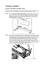

TREADMILL ASSEMBLY
PEDESTAL AND HANDLE ASSEMBLY STEPS
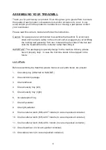
When you remove the treadmill from its box, first check to make sure all of the parts
are present. Then, read through the assembly instructions before you begin.
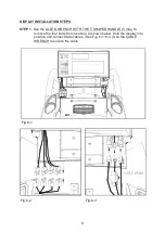
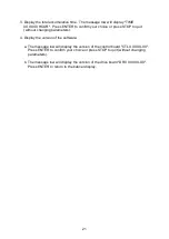
. Use the
to remove the screws (3 pcs)
from the side plates of the motor cover (both left and right) and remove
both side plates, then use the
to remove the screws and washers (6 sets) from the
pedestal bracket area. (See Fig. 1.)
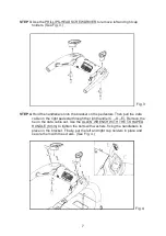
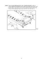
First, thread the data cable through the right pedestal. Then hold the right
pedestal onto the support bracket on the right side of the treadmill. Secure
the right pedestal by fastening the bolts with washers as shown. Hold the
left pedestal onto the support bracket on the left side of the treadmill.
Secure it by fastening the bolts with washers as shown. At this point, do
NOT tighten these bolts securely. Leave them slightly loose so that the
display can fit snugly. Tighten these bolts firmly after the display is attached.
Then, use the
to take down the screw and
washers on the top of the pedestal (C). (See Fig. 2.)
STEP 1
STEP 2.
PHILLIPS-HEAD SCREWDRIVER
ALLEN WRENCH WITH THE L-SHAPED
HANDLE (6 mm)
HEX ALLEN WRENCH (M6)
Fig.1
Fig.2
6
A
B
C


