SLM MANUAL
14
118073-001 Rev C
4.4 Control Circuits
Control circuits are used for regulation, monitoring,
pulse-width, control, slow-start and inhibit control.
Feedback signals are calibrated and buffered via general
purpose OP-AMPS. Pulse width control is accomplished
by a typical PWM type control I.C. Logic enable/disable
is provided by a logic gate I.C. Regulators generate ±
15Vdc and 10Vdc. DSP based control circuitry provides
excellent regulation, along with outstanding stability
performance
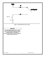
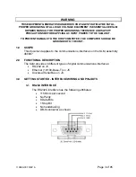
WARNING
LINE VOLTAGE IS PRESENT
WHENEVER THE POWER SUPPLY IS
CONNECTED TO EXTERNAL LINE
VOLTAGES. BE SURE TO DISCONNECT
THE LINE CORD BEFORE OPENING THE
UNIT. ALLOW 5 MINUTES FOR
INTERNAL CAPACITANCE TO
DISCHARGE BEFORE REMOVING ANY
COVER.
4.5 Options
Due to the variations of models and options provided in
the SLM series, details of actual circuits used may differ
slightly from above descriptions. Consult Spellman’s
Engineering Department for questions regarding the
principles of operations for the SLM series.
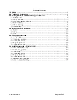
Summary of Contents for SLM SERIES
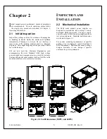
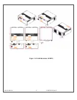
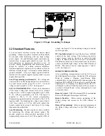
Page 15: ...SLM MANUAL 6 118073 001 Rev C Figure 2 2 Unit Dimensions 1200W ...
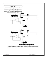
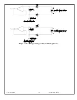
Page 19: ...SLM MANUAL 10 118073 001 Rev C Figure 3 3 Local Programming via External Voltage Source ...
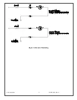
Page 20: ...SLM MANUAL 11 118073 001 Rev C Figure 3 4 Remote Monitoring ...
Page 40: ...Figure 9 Web Page 1 Contact Information 118080 001 REV A Page 13 of 95 ...
Page 98: ...Request Faults 68 20 ASCII 118080 001 REV A Page 71 of 95 ...