

SLM MANUAL
3
118073-001 Rev C
Watchdog Timer
If there is no communication between the HVPS and the
host computer for more than 10 seconds the HV output
will shutdown and the Watchdog Timer fault will be sent
via the digital communication when and if
communication is resumed. This can be enabled via the
digital communication and is defaulted to disable upon
power up.
Standard Input Features:
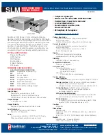
Power Factor and Universal Input:
The input voltage
of the SLM can operate within the range from 90Vac to
265Vac for the 300Watt model and at 180–264Vac, for
the 600Watt model. The power factor is actively
corrected across this entire range and is better than 0.99 at
full load.
Internal EMI Filter and Fuse Protection:
An internal
EMI filter and fuse provide protection against line voltage
surges and power supply faults.
Remote Operating Features
Remote Control:
USB, Ethernet and RS232 are standard.
A provided G.U.I allow user to control the unit via RS232
and USB interfaces. An imbedded Applet web browser
allow user to control the unit via Ethernet. Refer to SLM
digital protocol spec for details.
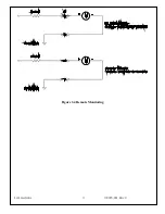
Remote Monitor:
Allows remote monitoring of the
Output voltage, current, HV On clock counter, and user
configurable firmware features via the USB, Ethernet or
RS232.
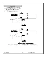
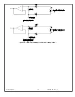
Remote Programming:
Allows remote programming of
the output voltage, current and user configurable firmware
features via the USB, Ethernet or RS232.
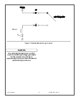
HV Enable/Interlock:
In local mode,
allows remote
ON/OFF control of the high voltage. In remote mode, the
hardware based dry contact closure must be closed in
order to enable the high voltage via the USB, Ethernet or
RS232.
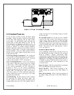
1.4 System Status and Fault
Diagnostic Display
If a fault occurs, the power supply will revert to the
Shutdown mode indicated by extinguishing of HV ON
LED and via RS-232 as HV OFF. To reset a fault in local
mode the enable must be reset. To reset a fault in remote
mode a HV ON or a RESET FAULTS command must be
sent via the RS-232, USB or Ethernet.
OVER CURRENT FAULT:
Indicates the over
current protection circuitry has caused the high
voltage to turn off. This fault will occur if the output
current exceeds 110% of full scale. If AOL is enable
this fault will occur when the current exceeds the
current program set point. This fault is indicated by
illumination of over current LED status on the front
panel and via RS-232, USB or Ethernet as Over
Current.
OVERVOLTAGE:
Indicates the over voltage
protection circuitry has caused the high voltage to
turn off. This fault will occur if the output voltage
exceeds 110% of full scale. If ROV is enable this
fault will occur when the voltage exceeds the
programmed ROV setpoint. This fault is indicated by
over voltage LED status on the front panel and via
the RS-232, USB or Ethernet as Over Voltage.
ARC FAULT
: Indicates that the programmed arc
count was exceeded within programmed time period.
This fault is indicated by steady state illumination of
Arc Fault LED status on front panel and via RS-232,
USB or Ethernet as Arc Fault. The LED will pulse
for each arc, but will be a steady state ON if a
shutdown occurs.
REGULATION ERROR:
Indicates a failure in the
voltage, current or power regulation circuitry. This
fault usually occurs when there is a lack of output
power to maintain regulation. This fault is indicated
by illumination of the Regulation Error LED status
on front panel and via RS-232, USB or Ethernet as
Under Current.
OVER TEMPERATURE:
Indicates either a failure
in the cooling system that would cause the internal
heat sink temperature to exceed the operating range
or the ambient temperature to exceed 40 degrees C,
resulting in shutdown of HV. This fault is indicated
by Over Temperature LED status on the front panel
and via RS-232, USB or Ethernet as Over
Temperature.
PS Fault Indication:
PS Faults an open collector
output with a 1k ohm impedance on J2-1, indicates
that a faults has occurred. High = no faults
HV On Indication:
HV On Signal is an open
collector output with a 1k ohm impedance on J2-14,
indicates that HV is enabled. High = HV OFF
HV On LED:
When the high voltage status is “On”
state it is indicated by HV ON LED status on the
front panel.
Summary of Contents for SLM SERIES
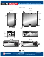
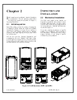
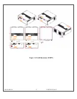
Page 15: ...SLM MANUAL 6 118073 001 Rev C Figure 2 2 Unit Dimensions 1200W ...
Page 19: ...SLM MANUAL 10 118073 001 Rev C Figure 3 3 Local Programming via External Voltage Source ...
Page 20: ...SLM MANUAL 11 118073 001 Rev C Figure 3 4 Remote Monitoring ...
Page 40: ...Figure 9 Web Page 1 Contact Information 118080 001 REV A Page 13 of 95 ...
Page 98: ...Request Faults 68 20 ASCII 118080 001 REV A Page 71 of 95 ...