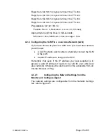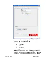
require reconfiguring the host computer with the correct host IP
address, subnet mask, and TCP port.
The device name does not affect the operation of the SLM; it is
simply a way for the user to differentiate multiple units on the same
network.
Depending on the type of network you are attaching the SLM to,
you may need to configure the host PC’s IP address and subnet
mask as shown in section 4.2.3.1. You can also test a network
connection to the SLM by following the instructions listed in section
4.2.3.2 .
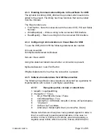
4.2.5 Enabling Communications Objects in Visual Basic for Ethernet
Communications
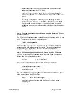
For Ethernet communications, we need Microsoft Winsock Control 6.0 and
SP5. To enable this in your VB 6 project, go to:
Project -> Components
Once selected in your toolbox, you will have an icon of two computers
linked together and will be named: Winsock. This can be dragged and
dropped into your application. Then set the object’s properties.
4.2.6 Configuring
Communications
in Visual Basic for Ethernet
In order to configure the Winsock Object, you must make the following
initialization in the object’s properties:
Protocol
0
–
sckTCPProtocol
Then, in the application code, include the following commands:
tcpClient.RemoteHost
=
host
tcpClient.RemotePort = portNumber
tcpClient.Connect
For further information regarding the use of the above commands, please
refer to your Visual Studio Help File.
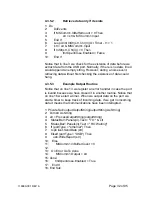
4.2.6.1
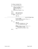
Data Output Example
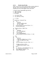
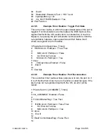
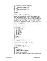
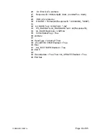
MSComm1 is both the serial and USB port. TcpClient is the
Ethernet port.
118080-001 REV A
Page 27 of 95
Summary of Contents for SLM SERIES
Page 15: ...SLM MANUAL 6 118073 001 Rev C Figure 2 2 Unit Dimensions 1200W ...
Page 19: ...SLM MANUAL 10 118073 001 Rev C Figure 3 3 Local Programming via External Voltage Source ...
Page 20: ...SLM MANUAL 11 118073 001 Rev C Figure 3 4 Remote Monitoring ...
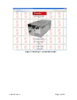
Page 40: ...Figure 9 Web Page 1 Contact Information 118080 001 REV A Page 13 of 95 ...
Page 98: ...Request Faults 68 20 ASCII 118080 001 REV A Page 71 of 95 ...

