64
M3i.48xx / M3i.48xx-exp Manual
Setting up the inputs
Analog Inputs
Setting up the inputs
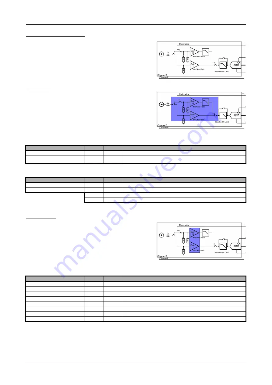
This analog acquisition board uses separate input stages and converters on each
channel. This gives you the possibility to set up the desired and concerning your
application best suiting input range also separately for each channel. All input
stage related settings can easily be set by the corresponding input registers. The
table below shows the available input stage registers and possible standard values
for your type of board. As there are also modified versions available with different
input ranges it is recommended to read out the currently available input ranges as
shown later in this chapter.
Input Path
Each input stage consists of different input paths each with different available set-
tings and features. Please refer to the technical data section to get details on the
differences of the input paths.
Offering different input paths gives the choice to adopt the cards input stage to
the specific application in the best technical way by either using a high frequency
50 ohm path to have full bandwidth and best dynamic performance or by using
a buffered path with all features but limited bandwidth and dynamic performance.
All following settings are related to the selected input path. To read available features like input ranges or termination settings it is first nec-
essary to set the input path for which the features are to be read.
The following registers show the available input path settings
Input ranges
This analog acquisition board has several different input ranges for each channel.
This gives you the possibility to set up the desired and concerning your application
best suiting input range also separately for each channel. The input ranges can
easily be set by the corresponding input registers. The table below shows the avail-
able input registers and possible standard ranges for your type of board. As there
are also modified versions available with different input ranges it is recommended
to read out the currently available input ranges as shown later in this chapter.
Please note that the available ranges need to be read out separately for each input
path. Please set the register SPC_READAIPATH as shown above to select the input path for which the settings should be read. The available
Input rages are read out using the following registers.
Register
Value
Direction
Description
SPC_READAIPATHCOUNT
3120
read
Returns the number of available analog input paths
SPC_READAIPATH
3121
read/write
Selects the input path which is used to read out the features. Please note that this settings does not
change the current path selection.
Register
Value
Direction
Description
SPC_PATH0
30090
read/write
Selects the analog input path for channel 0 (default path is path 0)
SPC_PATH1
30190
read/write
Selects the analog input path for channel 1 (default path is path 0)
0
Input Path 0: Buffered inputs
1
Input Path 1: HF input with fixed 50 ohm termination
Register
Value
Direction
Description
SPC_READAIPATH
3121
read/write
Selects the input path which is used to read out the features.
SPC_READIRCOUNT
3000
read
Returns the number of available input ranges for the input path selected by SPC_READAIPATH
SPC_READRANGEMIN0
4000
read
Reads the lower border of input range 0 in mV
SPC_READRANGEMIN1
4001
read
Reads the lower border of input range 1 in mV
...
...
...
SPC_READRANGEMAX0
4100
read
Reads the upper border of input range 0 in mV
SPC_READRANGEMAX1
4101
read
Reads the upper border of input range 1 in mV
...
...
...


