Chapter 6 – Replacing a QIP or Bus Expansion Module
58
5.
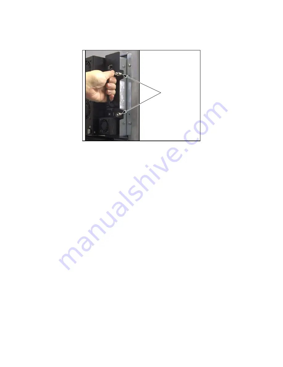
Use a #2 Phillips screwdriver to loosen the two captive screws on the right side of
the QIP (Figure 6-7).
6.
Pull firmly outward on the handle to remove the QIP from the library.
7.
Set the malfunctioning QIP aside for return to Spectra Logic.
Install the New QIP
1.
Remove the foam pin protector from the connector on the back of the QIP.
2.
Slide the new QIP into the emptied controller bay (Figure 6-7).
3.
Use a #2 Phillips screwdriver to tighten the two captive screws on the right side of
the QIP until the mounting plate is against the chassis.
4.
Install the SFPs you removed from the malfunctioning QIP into the ports on the
new QIP (see Figure 6-6 on page 57). The SFPs are keyed and only fit into the ports
one way.
5.
Reconnect any cabling you disconnected in Step 3 on page 57. Make sure you
connect the cables to the same connector locations as they were before.
6.
Reinstall the protective cover on the back of the library as described in
Install the
Cover
on page 20.
7.
Return to the Feedback Required screen displayed on the user interface (see Step 4
on page 57) and select
OK
.
The library powers on the new QIP and begins the process of configuring it. A
window displays showing the progress.
Figure 6-7
Removing and replacing a QIP.
Captive screws
Summary of Contents for T-Series Spectra T200
Page 1: ...Spectra T200 T380 Libraries Assisted Self Maintenance Guide PN 91010002 Revision A ...
Page 10: ...Contents 10 Notes ...
Page 26: ...Chapter 2 Using a USB Storage Device 26 Notes ...
Page 30: ...Chapter 3 Replacing the Air Filter 30 Notes ...
Page 62: ...Chapter 6 Replacing a QIP or Bus Expansion Module 62 Notes ...
Page 100: ...Chapter 9 Replacing the Transporter 100 Notes ...
Page 110: ...Index W 110 Notes ...


