Speck pumpen BADU BADUJET Turbo Pro Translation Of Original Operation Manual Download Page 27

Installation 

08|2020   EN 

27 

5.3 

Final assembly (Qualified specialist) 


 WARNING 

Risk of injury from sucking in/suction effect when the panel parts 
are not installed! 

  All panel parts 

must

 be mounted. 

All warranty and damage compensation rights will be voided for 
damages due to noncompliance or incorrect installation. 


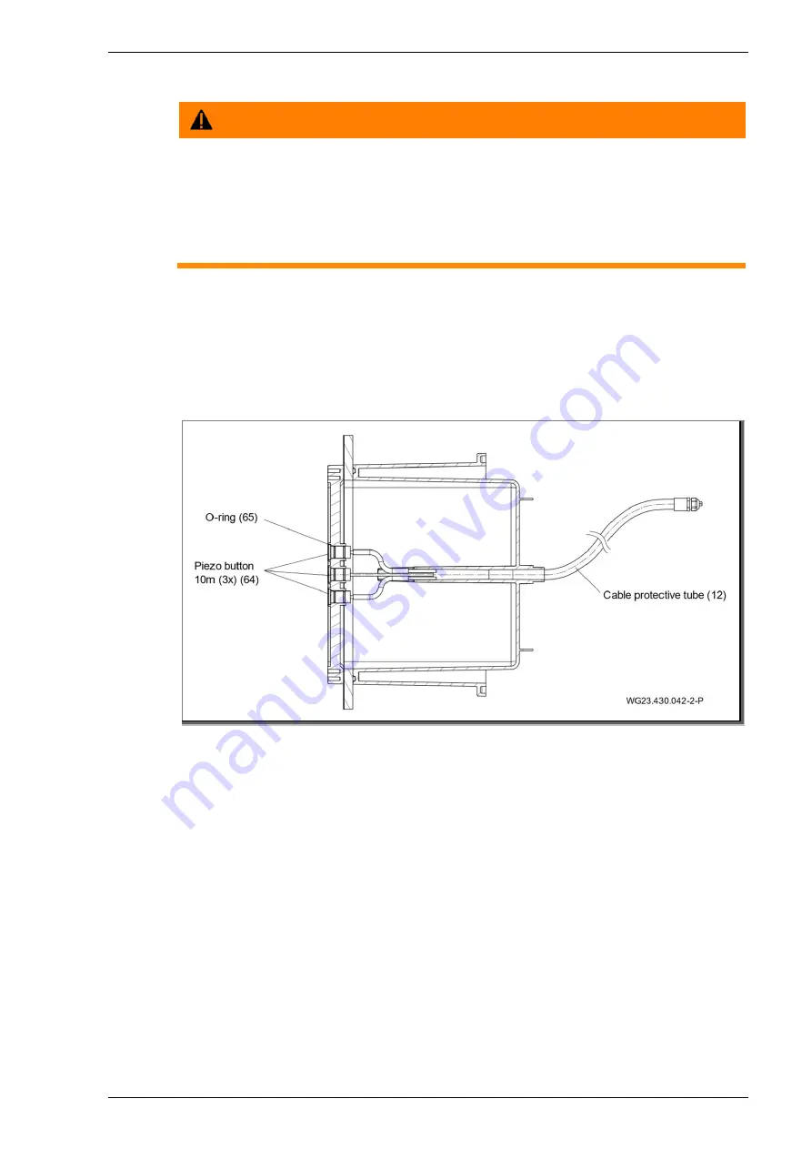
5.3.1  Installing the piezo buttons 

1.  Feed the three cables through the cylindrical guide of the 

plastic panel (5) and the installation housing (1). 

2.  Press in the piezo buttons (64) with two mounted O-rings 

(65) each up to the stop. 

3.  Tighten the hexagon nut of the cable gland. 


Fig. 12 


Summary of Contents for BADU BADUJET Turbo Pro

Page 1: ...EN EN Translation of original operation manual Submerged counter swim unit ...

Page 2: ...Fax 49 9123 949 260 info speck pumps com www speck pumps com All rights reserved Contents may not be distributed duplicated edited or transferred to third parties without the written permission of SPECK Pumpen Verkaufsgesellschaft GmbH This document and all attached documents are not subject to update service Subject to technical modifications ...

Page 3: ... parts 9 2 6 Signs 9 2 7 Residual risk 9 2 7 1 Falling parts 9 2 7 2 Rotating parts 10 2 7 3 Electrical energy 10 2 7 4 Hot surfaces 10 2 7 5 Suction danger 10 2 7 6 Body traps 11 2 7 7 Magnetic forces 11 2 7 8 Magnetic Field 11 2 7 9 Risk of injury at the inflow nozzle 11 2 7 10 Danger of drowning 11 2 8 Faults 11 2 8 1 Seized drive unit 11 2 9 Preventing material damage 12 2 9 1 Leakage at the i...

Page 4: ...ure borne and airborne noise transmission 17 5 1 5 Space requirements 17 5 1 6 Fastening elements 17 5 1 7 Swimming pool with overflow gutter 17 5 1 8 Frequency converter installation instructions 18 5 2 Installation Qualified specialist 19 5 2 1 Installation tip concrete pool 19 5 2 2 Installation note stainless steel foil pool 24 5 2 3 Cable protective tube 26 5 2 4 System shaft 26 5 2 5 Electri...

Page 5: ...rd circuit diagram 38 5 4 8 Terminal box connections 38 5 4 9 Displays on the frequency converter 39 5 4 10 Segment display green and orange LED fuse 39 5 4 11 DIP switch settings 40 5 5 Dismantling 40 6 Commissioning Decommissioning 41 6 1 Commissioning 41 6 1 1 Switching on the system 41 6 2 Operation 41 6 2 1 Switching on off 41 6 2 2 Volume regulation 42 6 2 3 Ball nozzle 43 6 3 Shutting down ...

Page 6: ...rs or operators of the product 1 2 Target group This instruction manual is aimed both at qualified specialists and the end customer Descriptions aimed only at qualified specialists are indicated accordingly qualified specialist This indication applies to the whole point All other points are universally valid 1 3 Other applicable documents Packing list Technical documents frequency converter 1 3 1 ...

Page 7: ...mage for better understanding or to optimise the workflow Important information and technical notes are specially marked to explain correct operation Symbol Meaning Instructions for a one step action 1 2 Directions for a multi step action Observe the order of the steps ...

Page 8: ...limited physical sensory or mental capacity or by people with a lack of experience or knowledge provided that they are supervised or have been instructed in the safe use of the unit and understand the resulting dangers Children may not play with the unit Cleaning and user maintenance may not be carried out by children without supervision Ensure that the following work is only performed by trained ...

Page 9: ...igns on the product Other applicable documents The valid national regulations for accident prevention The internal occupational operational and safety regulations of the operator 2 4 Protective equipment Reaching into moving parts e g coupling and or impeller fan can cause serious injury Never operate the pump unit without protective covers 2 5 Structural modifications and spare parts Alterations ...

Page 10: ...rotection according to DIN VDE 0100 702 Before working on the electrical system take the following measures Disconnect system from the power supply Attach a warning sign Do not switch on The system is being worked on Ensure that the system is free of voltage Check the electrical system regularly to ensure it is in proper working condition 2 7 4 Hot surfaces The electric motor can reach temperature...

Page 11: ...7 9 Risk of injury at the inflow nozzle The inflow nozzle operates with a high volume flow rate This can cause injuries to the eyes or other sensitive parts of the body Avoid direct contact of these parts of the body with the water jet from the inflow nozzle 2 7 10 Danger of drowning Danger of drowning due to strong current for persons of limited swimming ability and physical strength Adapt the sy...

Page 12: ...rs and splash water tank too small 2 9 3 Dry running Slide bearings and plastic parts can be destroyed within a few seconds when running dry Do not allow the unit to run dry This also applies to checking the rotation direction Only start the system when the water level is 350 mm above the system centre 2 9 4 Overheating The following factors can lead to overheating of the system Water level too lo...

Page 13: ... a dry room Drain the unit and pipes at risk of freezing in plenty of time 2 9 8 Water temperature The water temperature must not exceed 35 C 2 9 9 Safe use of the product Safe use of the product is no longer guaranteed in the following instances When the front panel is blocked When the drive unit is seized When protective devices e g front panel are damaged or missing When the electrical installa...

Page 14: ...eel or plastic pool with a smooth wall in the assembly area It is driven by a motor 20 the power of which can be adjusted in different stages by a frequency converter It is switched on and off and controlled by piezo buttons 64 in the front panel 55 and can also be adjusted by a remote control unit 66 The power is transmitted by a magnet coupled drive unit 2 3 to the propeller wheel 33 The water i...

Page 15: ...2020 EN 15 The flow direction can be set by swivelling a ball nozzle 42 5 in all directions using the adjustment aid 47 The powerful volume flow thus created gives the swimmer a personally adapted swimming experience ...

Page 16: ...pping screws and store in a safe place 4 3 Storage NOTICE Corrosion is possible due to storage in humid conditions with fluctuating temperatures Condensation can corrode windings and metal parts Store the drive unit in a dry place at constant temperature if possible NOTICE Damage or loss of individual parts Do not open the original packaging until installation or keep individual parts in the origi...

Page 17: ...rom motor to the wall min 300 mm Cooling of the motor and other system components for example switch cabinets and control units Limitation of the ambient temperature to maximum 40 C 5 1 4 Structure borne and airborne noise transmission Observe the regulations for constructional noise protection for example DIN 4109 Install the system so that the structure borne noise and airborne noise are reduced...

Page 18: ...re aggressive chemicals or potentially dangerous dust particles in the air Do not install the converter in the vicinity of heat sources with high radiation Protect against direct sunlight Install sun protection if necessary The installation site must be free from risk of frost The air flow through the converter may not be obstructed The heat from the converter must dissipate naturally A suitable p...

Page 19: ...Installation 08 2020 EN 19 5 2 Installation Qualified specialist 5 2 1 Installation tip concrete pool Concrete pool with foil Fig 2 Tiled concrete pool Fig 3 ...

Page 20: ...Installation 20 EN 08 2020 Pool cutout for concrete pools formwork Fig 4 ...

Page 21: ...Installation 08 2020 EN 21 Installation of formwork for concrete pools Fig 5 ...

Page 22: ...th a drop of instant glue on the floor side 5 Place the sealing beading 16 in the groove 6 Align the installation housing 1 according to the label OBEN UP HAUT and fix to the casing with the tapping screws 51 The rectangular cut out in the casing is optional This serves for inspection or correct seating or also later installation of the support slats When concreting make sure that the concrete is ...

Page 23: ...il it is recommended to reduce the rectangular cut out all round to increase the distance from the holes The overhanging foil can be stuck to the inside of the housing Installation diagram for installation in a tiled concrete pool Fig 7 NOTICE Note for tiled concrete pool After the concrete has hardened tiles can be mounted around the panel at a distance of approx 1 cm Sealing must be applied as a...

Page 24: ...Installation 24 EN 08 2020 5 2 2 Installation note stainless steel foil pool Foil pool Fig 8 Stainless steel plastic pool Fig 9 ...

Page 25: ...he rectangular cut out all round to increase the distance from the holes The overhanging foil can be stuck to the inside of the housing 3 Clamp support slats 17 between the two overlaps of the inside of the housing 4 Press in the foam rubber seal 11 without tension along the groove on the housing 1 by hand Fix with a drop of instant glue on the floor side 5 Align the installation housing 1 accordi...

Page 26: ... a possibility for fastening the frequency converter and the switch cabinet as well as the cable protection tube above water level if possible There must be a potential equalisation connection in the shaft See point 0 on page 31 There must be sufficient room for installation and removal of the motor and drive unit 5 2 5 Electrical control The terminal box for the countercurrent system must be acco...

Page 27: ... All warranty and damage compensation rights will be voided for damages due to noncompliance or incorrect installation 5 3 1 Installing the piezo buttons 1 Feed the three cables through the cylindrical guide of the plastic panel 5 and the installation housing 1 2 Press in the piezo buttons 64 with two mounted O rings 65 each up to the stop 3 Tighten the hexagon nut of the cable gland Fig 12 ...

Page 28: ...nozzle unit 4 for a pool wall thickness from 3 5 mm up to max 27 mm The adapter height must be chosen so that the round panel 52 has no gap bigger than 8 mm from the maximally swivelled ball nozzle 42 in the installed state The following order kits must be used above a wall thickness of 7 mm Wall thickness mm Adapter type Screw length mm Order kit 0 to 3 5 40 above 3 5 to 7 Washer 3 5 40 above 7 t...

Page 29: ...anel 5 2 Align the stainless steel panel 55 to the plastic panel 5 3 Tighten the 12 tapping screws 6 x 22 56 with a torque of 6 Nm Fig 14 5 3 5 Installing the drive unit 1 Pull the O ring 36 onto the propeller unit 3 2 Insert the propeller unit 3 centrally with the orientation pin in 6 o clock position on the housing centring flange centring 3 Tighten 10 hexagon socket head tapping screws 7x48 37 ...

Page 30: ...6 hexagon socket head tapping screws 7 x 48 29 with a torque of 9 Nm CAUTION Risk of injury due to magnetic forces Pay attention to this when installing removing the motor unit Fig 15 5 3 7 Possibilities for using the connection nozzle rear wall The connection nozzle c can be used for active overwintering circulation avoidance of accumulation of water in the installation housing emptying ...

Page 31: ... intended It must not be bridged or manipulated in any other way This applies equally in commissioning or repair situations The manufacturer must be contacted for integration of other safety switches in the stop circuit of the frequency converter FC Trip WARNING Risk of electric shock from residual charge of the frequency converter capacitors Work may be carried out on the load current circuit aft...

Page 32: ...e B rated error current IFN 30 mA Only use suitable pipe types according to regional regulations Adjust minimum diameter of the electrical pipes to accommodate the motor output and pipe length Do not bend or squash the pipes If hazardous situations can occur provide an emergency off switch according to DIN EN 809 The builder operator must make a decision according to this standard The included cab...

Page 33: ...otor for potential equalisation See the wiring diagrams for additional information The parts named above are not part of the scope of supply and must be provided by the customer when installing the system 5 4 2 Connection diagram The diagram below shows an overview of how all the connections are to be wired The on site wiring of the motor cable and control cable is explained in separate chapters F...

Page 34: ...Installation 34 EN 08 2020 5 4 4 Control cable wiring diagram Fig 18 ...

Page 35: ...steps 1 Shorten the cable if necessary customer end 2 Plug the cap and the plastic inlay of the EMC gland onto the cable The lugs on the plastic part must face towards the end of the cable 3 The end of the cable must be stripped over a length of 14 cm To strip the sheath it must be slit carefully lengthwise 4 Open the shield around the wires and fold back Cut off the shield to a length of 2 cm 5 R...

Page 36: ...le strain relief 11 The rest of the EMC gland must be screwed into the feed through plate on the frequency converter Align the claws of the enclosed lock nut to the feed through plate Do not remove the feed through plate 12 The wires U V W must be inserted into the plug Observe the labelling The plug contacts must be opened first if necessary 13 Fasten the earthing cable with the ring cable shoe i...

Page 37: ...ing Make sure that the lugs on the plastic part grip into the groove Only then is the position of the plastic part interlocked Remove the transport cap and O ring from the motor plug The motor plug rotates The cable and motor are connected by a bayonet catch 5 4 6 Wiring diagram 3 phase 400 230V 50 Hz Fig 19 ...

Page 38: ...Installation 38 EN 08 2020 5 4 7 On off board circuit diagram Fig 20 5 4 8 Terminal box connections Fig 21 ...

Page 39: ...by the piezo buttons on the system or on the remote control unit 5 4 10 Segment display green and orange LED fuse Fig 22 RUN flashes when the microprocessor is working S1 lights up when one of the pump s buttons is pressed P lights up the pump should now work and the pump s protection should be on P flashes the pump should be turned on in time mode and the pump s protection should be on S2 lights ...

Page 40: ...due to the inrush current in the LED lighting module FV lights up if the voltage in the microprocessor overloads Green and orange LEDs on the circuit board green LED lights up Power supply present in the circuit board Volt orange LED lights up Motor protection has triggered over current Check the motor protection settings Circuit board fuse Replaceable fuse 3 15 A T The fuse only needs replacing i...

Page 41: ...ont of the outflow nozzle In case of incorrect rotation direction switch off the system immediately and check the connections of the motor or the orange cable check wire labelling according to the circuit diagram specifications and connect correctly The motor can be switched on by the preceding frequency converter 61 directly on the operating panel 55 at the piezo buttons 64 in the pool or with th...

Page 42: ...ote control Increase volume flow Reduce volume flow The system can be controlled over a speed range from 750 rpm to 1650 rpm The individual power stages are additionally indicated visually by changing colours on the buttons yellow flashing 1650 rpm yellow 1500 rpm violet 1350 rpm green 1200 rpm blue System off red System on green 1200 rpm turquoise 1050 rpm blue 900 rpm blue flashing 750 rpm In th...

Page 43: ...crew 6 3 Shutting down 1 Switch off the system and disconnect from the mains 2 Lower the water level in the swimming pool to the lower edge of the panel 6 3 1 Wintering over For outdoor countercurrent systems which could be endangered by frost during the winter Active overwintering Formation of ice can be prevented by circulating the water by connecting a filter pump to the nozzle c Passive overwi...

Page 44: ...an electrician Frequency converter not connected correctly Plug the connection correctly bayonet catch Problem Piezo button does not light Possible cause Solution Cable wired incorrectly Check and set correctly Sensor defective Check and replace if necessary Problem Radio transmitter does not work Possible cause Solution Battery inserted incorrectly or dead Insert battery the right way round Repla...

Page 45: ... long in operation at max speed Adapt operating time Problem Wrong rotation direction of the turbine Possible cause Solution Wiring not according to circuit diagram Have it checked by an electrician Problem Magnetic coupling is disengaged Possible cause Solution Damage to the magnet unit or plain bearing Contact customer services Impeller is blocked Clean interior parts Problem Error in the freque...

Page 46: ...ous water components the parts made of stainless steel have to be cleaned periodically to avoid possible corrosive damage 8 1 Warranty The warranty includes the devices delivered and all components However natural wear and tear DIN 3151 DIN EN 13306 on all turning and dynamically loaded components including electronic components under tension is not covered under the warranty Failure to comply wit...

Page 47: ... end of its service life the pump unit or individual components must be disposed of correctly Disposal in the household waste is not permitted Dispose of the packaging materials in the household waste in accordance with the local regulations ...

Page 48: ...r output P2 kW 3 3 00 Number of nozzles Ø 172 mm 1 Outflow speed m s 1 80 4 10 Nozzle swivellable to all sides degrees 5 Net weight kg 51 50 Pos 156 Technische Dokumentation Speck Pumpen Betriebsanleitung Technische Daten Maßzeichnung 3 mod_1439965097337_370 docx 40120 2 1 10 1 Dimensional drawing Fig 24 Fig 25 ...

Page 49: ...Technical Data 08 2020 EN 49 10 2 Exploded drawing Fig 26 ...

Page 50: ...ommissioning 42 Defects Overview 45 Disposal 48 E Electrical connection 32 F Faults 11 45 Frost 13 I Installation 17 19 Intended use 8 M Maintenance 47 O Operation 42 Q Qualified specialist 17 19 32 S Spare parts 9 Storage 16 T Transport 16 W Warranty 47 ...

Reviews: