background image

9

ENGLISH

SPIRE XL 440 User manual

female connectors. The shield connection is pin 1, while pin 2 is Data Negative (S-), and 

pin 3 is Data positive (S+).

  CAUTION: Wires must not come into contact with each other; otherwise the 

fixtures will not work at all, or will not work properly. 

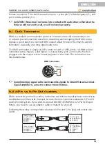
5.1.  DMX Terminator

DMX is a resilient communication protocol, however errors still occasionally occur. 

In order to prevent electrical noise from disturbing and corrupting the DMX control 

signals, a good habit is to connect DMX output of last fixture in the chain to a DMX 

terminator, especially over long signal cable runs.

The DMX terminator is simply an XLR connector with a 120Ω (ohm), 1/4 Watt resistor 

connected across Signal (-) and Signal (+), respectively, pins 2 and 3, which is then 

plugged into the output socket on last projector in the chain. The connections are 

illustrated below.

120ohm, 1/4 W

Resistor

DMX Terminator

  Complimentary signal cable can transmits signals to 20 unit fixtures at most. 

Signal amplifier is a must to connect more fixtures.

5.2. 3-Pin vs 5-Pin DMX cables

DMX connection protocols used by controllers and fixtures manufacturers are not stan

-

dardized around the world. However, two are the most common standards: 5-Pin XLR 

and 3-Pin XLR system. If you wish to connect MOOD 185 WASH to a 5-Pin XLR input 

fixture, you need to use an adapter-cable or make it by yourself.
Following the wiring correspondence between 3-Pin and 5-Pin plug and socket stan

-

dards

5-Pins XLR (plug)

Pin 1: GND (Screen)

Pin 2: Signal (-)

Pin 3: Signal (+)

Pin 4: N/C

Pin 5: N/C

3-Pins XLR (socket)

Pin 1: GND (Screen)

Pin 2: Signal (-)

Pin 3: Signal (+)

5-Pins XLR (socket)

Pin 1: GND (Screen)

Pin 2: Signal (-)

Pin 3: Signal (+)

Pin 4: N/C

Pin 5: N/C

3-Pins XLR (plug)

Pin 1: GND (Screen)

Pin 2: Signal (-)

Pin 3: Signal (+)

Summary of Contents for Spire XL 440

Page 1: ...SPIRE XL 440 Moving Head Beam Spot Wash 20R Please read this manual carefully and properly take care of it USER MANUAL Leggete questo manuale e conservatelo per future consultazioni MANUALE UTENTE ...

Page 2: ... an incorrect operation can cause damages to you and to the unit Take care The SOUNDSATION Team Gentile Cliente Grazie per aver scelto un prodotto SOUNDSATION La nostra missione è quella di offrire ai nostri utenti una vasta gamma di strumenti musicali ed apparecchiature audio e lighting con tecnologie di ultima generazione Speriamo di aver soddisfatto le vostre aspettative e se voleste collaborar...

Page 3: ...ION 13 9 LCD TOUCH SCREEN OPERATION 14 9 1 Address Menu 14 9 2 Workmode Menu 16 9 3 Display menu 18 9 4 Scene Menu 21 9 5 Advanced Menu 24 9 6 Status Menu 25 9 7 Escape Funcion 26 10 DMX CHANNEL MODES 27 10 1 23CH DMX Channel Mode 27 10 2 26CH DMX Channel Mode 31 11 GOBO and COLOR WHEELS 35 11 1 Color Wheel 35 11 2 Fixed Gobo Wheel 1 35 11 3 Fixed Gobo Wheel 2 36 11 4 Rotating Gobo Wheel 36 12 TRO...

Page 4: ...anger of injury or death to the operator CAUTION Describes precautions that should be observed to prevent danger of the apparatus To protect the environment please try to recycle the packing material as much as possible The projector is for indoor use only IP20 Use only in dry locations Keep this device away from rain and moisture excessive heat humid ity and dust Do not allow contact with water o...

Page 5: ... cord from being walked on or pinched particularly at plugs convenience receptacles and the point where they exit from the apparatus Do not defeat the safety purpose of the polarized or grounding type plug A polarized plug has two poles a grounding type plug has two poles and a third grounding terminal The third prong is provided for your safety If the provided plug does not fit into your outlet r...

Page 6: ...g head Enjoy your new equipment and make sure to read this manual carefully before operation This user manual is made to provide both an overview of controls as well as informa tion on how to use them In order to help you to understand the connections between the various controls we have gathered in groups according to their functions 1 1 UNPACKING Your SPIRE XL 440 moving head was carefully packe...

Page 7: ... the effects allow the use as Beam Spot or Wash fixture The quality of mechanics motor precision and high technology controls allow accurate silent and precise movements The presence of three gobos wheels one color wheel with CTO CTW and CMY filters and two prisms make easy to play with color palette and effects to satisfy even the most demanding light designers The 3 7 touch screen display and th...

Page 8: ... connecting power Wire correspondence is as follows Cable EU Pin International Brown Live L Blue Neutral N Yellow Green Earth The earth must to be connected Pay attention to the safety Before taking into operation for the first time the installation has to be approved by an expert 5 DMX CONNECTION DMX fixtures are designed to receive data through a serial Daisy Chain A Daisy Chain connection is wh...

Page 9: ...o the output socket on last projector in the chain The connections are illustrated below 120ohm 1 4 W Resistor DMX Terminator Complimentary signal cable can transmits signals to 20 unit fixtures at most Signal amplifier is a must to connect more fixtures 5 2 3 Pin vs 5 Pin DMX cables DMX connection protocols used by controllers and fixtures manufacturers are not stan dardized around the world Howe...

Page 10: ...The fixture should be installed outside areas where persons may walk by or be seated IMPORTANT Overhead rigging requires extensive experience including but not limited to calculating working load limits installation material being used and periodic safety inspection of all installation material and the pro jector If you lack these qualifications do not attempt the installation your self but instea...

Page 11: ...hers always supplied with the clamp f f Place the plugs with wings n 3 in the direction of the holes n 5 placed under the base of the moving head Screw them clockwise for about 90 until you hear a click that indicates the achievement of the correct and safe position f f Hook the moving head to the truss through the two clamps now perfectly fixed to the base and screw the wing screw n 4 so as to ti...

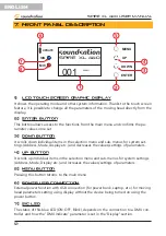
Page 12: ...the selection menu and sub menus for system set tings Address Mode Display etc and decreases the values settings of parameters 4 UP BUTTON It scrolls up individual items in the selection menu and sub menus for system settings Address Mode Display etc and increases the values settings of parameters 5 MENU BUTTON Pressing this button returns to the main menu 6 POWER USB Connection External power fun...

Page 13: ...ith F10AL 250 V fuse 5 x 20 mm In case of fuse burn to prevent the risk of fire and damaging the unit please use only a spare of the recommended fuse type as described Before replacing the fuse make sure the unit turned off and discon nected from the AC outlet 3 POWER IN SOCKET Plug the power cord into an AC socket properly configured for your particular model 4 DMX INPUT Male 3 pin XLR sockets fo...

Page 14: ...ired sub menu which can be accessed by pressing the ENTER button on the control panel The desired sub menu can be accessed directly by touching the graphic button shown on the display 9 1 Address Menu The Address Menu allows you to set the DMX channel the DMX Mode and also to re set the machine To access this sub menu touch the ADDRESS graphic button on the display figure below SUPER CMY SPOT 3IN1...

Page 15: ... a window will open to make the change figure below Address Workmode Display Scene Advanced Status Escape 001 23CHB 01 01 Previous Next Channel SysRst Address Workmode Display Scene Advanced Status Escape Previous Next Channel SysRst 001 23CHB 01 01 001 Address By using the UP DOWN buttons on the control panel it is possible to modify the DMX address value By pressing the ENTER button on the contr...

Page 16: ...ons on the control panel you can select the desired operating mode and then by pressing the ENTER button on the control panel it will be actitvated To exit the Workmode sub menu press the MENU button on the control panel The device will return to display the main menu When an operating mode is selected on the left side of the display the symbol is shown All the operations explained above are also ...

Page 17: ...he selection of the desired scenario or the Scene Auto mode can also be made using the buttons on the control panel The UP DOWN buttons must be used to select the Scene operating mode and the ENTER button to activate this mode Once this operating mode has been selected the ENTER button can be used to select one of the 10 scenarios or Auto scene mode In the main menu at the bottom left the display ...

Page 18: ...indow will open to confirm the lamp ON OFF operation In the main menu at the bottom the information related to the lamp will be the change color of the lamp symbol Black Off Yellow On 00 58 17 DISPLAY STATUS SCEN 12 0 NOR FULL 9 3 Display menu This sub menu can be accessed both from the main menu and from the window where all the sub menus are listed as shown in the figure below SUPER CMY SPOT 3IN...

Page 19: ... position will be automatically detected and then the display will be rotated in the right direction DMX Signal LED It selects the indication mode for the SIG LED on the front panel Mode1 The SIG LED lights on when there is a DMX signal and goes off when there is no signal Mode2 The SIG LED is off when there is a DMX signal and lights up when there is no signal Mode3 The SIG LED blinks when there ...

Page 20: ...ene Advanced Status Escape Screen Saver DMX Indicate Signal Bright 010 Screen Light English OFF Screen Rot Auto Mode3 010 Touch Enable OFF Touch Rectify Sound Ctrl Scene Mode Auto M S Choose Master Touch Enable SURE NO Once the Touch function is disabled to re enable it use the UP and DOWN but tons on the control panel The Touch Enable window will appear again and using the UP and DOWN buttons you...

Page 21: ...perating mode For further details see 9 2 Workmode Menu on page 16 In each scenario it is possible to modify and set all the parameters listed below To select the parameters you can use the UP and DOWN buttons and then the EN TER button on the control panel to enter the edit window where again using the UP and DOWN buttons you can change the value of the selected parameter Once the desired value h...

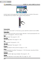
Page 22: ...when the scene operating mode is set to Auto The range is 0 255 0s 25 5s Pan Pan adjustment The range is 0 255 Pan Fine Fine Pan adjustment The range is 0 255 Tilt Tilt adjustment The range is 0 255 Tilt Fine Fine Tilt adjustment The range is 0 255 PT Spd Speed adjustment for Pan and Tilt The range is 0 255 Frost Enable Disable the Frost filter The range is 0 255 If the value is less than 128 the ...

Page 23: ...wheel The range is 0 255 Gobo Rot Wh Select the desired gobo in the rotating wheel The range is 0 255 Gobo Self Rot Select the rotation mode for the gobo rotating wheel The range is 0 255 Prism1 Enable Disable the Prism1 The range is 0 255 If the valueis less than 128 the Prism1 is disabled Prism1 R Select the rotation mode for Prism1 The range is 0 255 Prism2 Enable Disable the Prism2 The range i...

Page 24: ...de Factory Setting OFF 010 010 Manual Pan Invert Tilt Invert OFF ON OFF To select the parameters you can use the UP and DOWN buttons and then the EN TER button on the control panel The parameter to be modified can also be selected with the touch of a finger directly on the screen Pan Invert Set the PAN rotation direction It can be OFF normal or ON inverted Tilt Invert Set the TILT rotation directi...

Page 25: ... this option the device will be reset with all the default settings 9 6 Status Menu This sub menu can be accessed both from the main menu and from the window where all the sub menus are listed as shown in the figure below SUPER CMY SPOT 3IN1 001 23CHB 01 01 00 58 17 ADDRESS WORKMODE DISPLAY SCENE ADVANCED STATUS 001 12 0 NOR FULL Address Workmode Display Scene Advanced Status Escape DMX Ctrl Auto ...

Page 26: ...n in the figure below 00 58 17 DISPLAY STATUS 001 12 0 ERR FULL Fixture Status Display key data status of the fixture such as communication quality Light temperature sensors temperature etc Version Information Display the information related to the fixture including the version These information are an important reference for the maintenance Light time The usage partial time of the lamp is indicat...

Page 27: ... Color 4 36 42 Color 5 43 49 Color 6 50 56 Color 7 57 63 Color 8 64 70 Color 9 71 77 Color 10 78 85 Color 11 86 92 Color 12 93 99 Color 13 100 106 Color 14 107 113 Color 15 114 120 Color 16 121 127 Color 17 128 134 Color 18 135 141 Color 19 142 148 Color 20 149 155 Color 21 156 162 Color 22 163 170 Color 23 171 177 Color 24 178 184 Color 25 185 191 Color 26 192 198 Color 27 199 205 Color 28 206 21...

Page 28: ...Pattern 11 60 64 Pattern 12 65 69 Pattern 13 70 74 Pattern 14 75 79 Pattern 1 Shake from slow to fast 80 84 Pattern 2 Shake from slow to fast 85 89 Pattern 3 Shake from slow to fast 90 94 Pattern 4 Shake from slow to fast 95 99 Pattern 5 Shake from slow to fast 100 104 Pattern 6 Shake from slow to fast 105 109 Pattern 7 Shake from slow to fast 110 114 Pattern 8 Shake from slow to fast 115 119 Patt...

Page 29: ... fast 171 180 Pattern 8 Shake from slow to fast 181 191 Pattern 9 Shake from slow to fast 192 223 Forwad Flows from fast to slow 224 255 Reverse Flows from fast to slow CH9 ROTATING GOBO 0 10 White 11 20 Pattern 1 21 30 Pattern 2 31 40 Pattern 3 41 50 Pattern 4 51 60 Pattern 5 61 70 Pattern 6 71 80 Pattern 7 81 90 Pattern 1 Shake from slow to fast 91 100 Pattern 2 Shake from slow to fast 101 110 P...

Page 30: ... 187 Forwad Flow from fast to slow 188 195 Stop 196 255 Reverse Flow from fast to slow CH15 Zoom 0 255 From small to large CH16 Focus 0 255 From far to near Ch17 Frost 0 127 Frost Filter not active 128 255 Frost Filter active CH18 Pan 0 255 0 540 degrees CH19 Fine Pan 0 255 0 2 degrees CH20 Tilt 0 255 0 270 degrees CH21 Fine Tilt 0 255 0 1 degrees CH22 Pan and Tilt Speed 0 255 From fast to slow CH...

Page 31: ...7 From slow to fast shade strobe 208 212 Light On 213 251 From slow to fast random strobe 252 255 Light On CH9 C 0 255 0 100 Cyan CH10 M 0 255 0 100 Magenta CH11 Y 0 255 0 100 Yellow CH12 Colors 1 0 21 Color 1 22 42 Color 2 43 62 Color 3 63 85 Color 4 86 106 Color 5 107 127 Color 6 128 190 Forward colors flow Fast to Slow 191 255 Reverse colors flow Slow to Fast CH13 Colors 2 0 21 Color 1 22 42 Co...

Page 32: ... 85 Color 11 86 92 Color 12 93 99 Color 13 100 106 Color 14 107 113 Color 15 114 120 Color 16 121 127 Color 17 128 134 Color 18 135 141 Color 19 142 148 Color 20 149 155 Color 21 156 162 Color 22 163 170 Color 23 171 177 Color 24 178 184 Color 25 185 191 Color 26 192 198 Color 27 199 205 Color 28 206 212 Color 29 213 219 Color 30 220 226 Color 31 227 233 Color 32 234 240 Color 33 241 247 Color 34 ...

Page 33: ...m slow to fast 120 124 Pattern 10 Shake from slow to fast 125 129 Pattern 11 Shake from slow to fast 130 134 Pattern 12 Shake from slow to fast 135 139 Pattern 13 Shake from slow to fast 140 191 Pattern 14 Shake from slow to fast 192 223 Forwad Flow from fast to slow 224 255 Reverse Flow from fast to slow CH17 GOBO 2 0 10 White 11 20 Pattern 1 21 30 Pattern 2 31 40 Pattern 3 41 50 Pattern 4 51 60 ...

Page 34: ... Shake from slow to fast 151 199 Forwad Flows from fast to slow 200 202 Stop 203 255 Reverse Flows from fast to slow CH19 Gobo Self Rotate 0 127 0 360 degrees 128 187 Forwad Flow from fast to slow 188 195 Stop 196 255 Reverse Flow from fast to slow CH20 PRISM 1 0 127 Prism 1 not active 128 255 Prism 1 active CH21 Prism 1 Rotation 0 127 0 360 degrees 128 187 Forwad Flow from fast to slow 188 195 St...

Page 35: ...Resets Effect after more than 3 sec onds 240 255 Resets the device after more than 3 seconds 11 GOBO and COLOR WHEELS As already mentioned in the main features the device is equipped with 2 Fixed Gobo wheels and 1 Rotating Gobo wheel all with Bi Directional Flow Effect 11 1 Color Wheel 11 2 Fixed Gobo Wheel 1 ...

Page 36: ...36 ENGLISH SPIRE XL 440 User manual 11 3 Fixed Gobo Wheel 2 11 4 Rotating Gobo Wheel ...

Page 37: ... cables Conflict between tracking and vector control Eliminate scene cross fade on con troller Data link not terminated Insert termination plug in output of last fixture Defective fixture or 2 devices transmitting on link Bypass fixtures one at a time until normal operation is regained unplug both connectors and connect them directly together Colors cannot be mixed Random color mixing is on Turn o...

Page 38: ...ass endless rotation white open bi direction flow effect Color wheel 12 color 2 CTO 1 CTB 1 CMY White open semi color effect Prism 1 8 Facet Prism 2 16 Facet Shutter 1 20t s Focus Zoom Beam angle 2 3 56 with linear focusing zoom Strobe 1 20Hz support mechanical strobe and adjustable speed strobe X Y scan Pan 540 Tilt 270 3 phase motors with photoelectric reset and correction Control Panel Display ...

Page 39: ...e at SOUNDSATION s discretion either by repair or by exchanging individual parts or the entire appliance Any defective parts removed from a product during the course of a warranty claim shall become the property of SOUND SATION While under warranty period defective products may be returned to your local SOUNDSATION dealer together with original proof of purchase To avoid any damag es in transit pl...

Page 40: ...o an authorized collection site for recycling waste electrical and electronic equipment WEEE Improper handling of this type of waste could have a possible negative impact on the environment and human health due to potentially hazardous substances that are gen erally associated with EEE At the same time your cooperation in the correct disposal of this product will contribute to the effective usage ...

Page 41: ...CRIZIONE DEL PANNELLO POSTERIORE 51 9 FUNZIONAMENTO DEL TOUCH SCREEN LCD 52 9 1 Menu Address 52 9 2 Menu Workmode 54 9 3 Menu Display 56 9 4 Menu Scene 59 9 5 Menu Advanced 62 9 6 Menu Status 63 9 7 Funzione Escape 64 10 MODALITÀ CANALE DMX 65 10 1 Modalità Canale DMX 23CH 65 10 2 Modalità Canale DMX 26CH 69 11 RUOTE GOBO e COLORI 73 11 1 Ruota Colori 73 11 2 Ruota fissa Gobo 1 73 11 3 Ruota fissa...

Page 42: ...mento o di morte per l utilizzatore CAUTION Precauzioni da osservare per evitare danni all apparecchio Per proteggere l ambiente provare a riciclare il materiale di imballaggio il più possibile Il proiettore è solo per uso interno IP20 Usare solo in luoghi asciutti Tenere il dispositivo lontano da pioggia e umidità calore eccessivo umidità e polvere Non permettere il contatto con acqua o altri liq...

Page 43: ...chiacciato in particolare in prossimità delle spine delle prese e del punto in cui fuoriesce dall apparecchio Non vanificate la finalità di sicurezza della spina con messa a terra Una spina normale o polarizzata ha due soli terminali una spina con messa a terra ha un terzo polo di terra Questo ulteriore terminale serve per la vostra sicurezza Se la spina fornita non si inserisce nella presa consul...

Page 44: ... il dispositivo Questo manuale utente è stato creato per fornire sia una panoramica dei controlli sia informazioni su come usarli Per aiutarvi a capire le connessioni tra i vari controlli questi sono stati riuniti in gruppi in base alle loro funzioni 1 1 Disimballaggio La testa mobile SPIRE XL 440 è stata accuratamente imballata per garantire un tra sporto sicuro Nonostante questo si consiglia di ...

Page 45: ...ffetti ne consento l uso sia come Beam Spot o Wash La qualità delle meccaniche la precisione dei motori e l elevata tecnologia dei controlli consentono di ottenere movimenti accurati silenziosi e precisi La presenza tra i vali colori di filtri CTO CTW e CMY le tre ruote gobos i due prismi permettono di allargare enormemente le palette di colori e degli effetti a in grado di soddisfare anche i ligh...

Page 46: ...sse della tensione e della frequenza del dispositivo quando si collega l alimentazione La corri spondenza dei fili è la seguente Cavo EU Piedino Internazionale Marrone Fase L Blu Neutro N Giallo Verde Terra La terra deve essere collegata Prestare attenzione alla sicurezza Prima di mettere in funzione per la prima volta l installazione deve essere approvata da un esperto 5 CONNESSIONE DMX Gli appar...

Page 47: ...20Ω ohm 1 4 Watt collegato attraverso il segnale e il segnale rispettivamente i pin 2 e 3 che viene quindi inserito nella presa di uscita sull ultimo proiettore nella catena Le connessioni sono illustrate di seguito 120ohm 1 4 W resistenza Terminatore DMX Un cavo di segnale DMX standard può trasmette segnali a 20 unità al massi mo E necessario un amplificatore di segnale per collegare più apparecc...

Page 48: ...sedersi o camminare IMPORTANTE Le installazioni su impalcature alte richiedono una grande esperienza incluso ma non limitato a il calcolo dei limiti di carico del ma teriale di installazione utilizzato per il quale va effettuata una ispezione pe riodica di sicurezza estesa anche al proiettore In assenza di tali requisiti non si deve tentare l installazione da soli avvalendosi invece di un installa...

Page 49: ... fornite sempre con il morsetto f f Posizionare i tappi con le alette n 3 nella direzione dei fori n 5 posti sotto la base della testa mobile Avvitarli in senso orario per circa 90 fino a quando si sentirà un clic che indica il raggiungimento della posizione corretta e sicura f f Agganciare la testa mobile al traliccio o travatura tramite i due morsetti già per fettamente fissati alla base e avvit...

Page 50: ...elementi nel menu di selezione e sottomenu per le impostazioni di sistema Indirizzo Modalità Display ecc e decrementa i valori im postazioni dei parametri 4 PULSANTE UP Scorre verso l alto singoli elementi nel menu di selezione e sottomenu per le impostazi oni di sistema Indirizzo Modalità Display ecc e incrementa i valori impostazioni dei parametri 5 PULSANTE MENU Premendo questo pulsante si rito...

Page 51: ...le con fusibile F10AL 250 V fuse 5 x 20 mm In caso di bruciatura del fus ibile per prevenire il rischio di incendio e di danneggiare l unità utilizzare solo un tipo di fusibile consigliato come descritto Prima di sostituire il fusibile assicurarsi che l unità sia spenta e scollegata dalla presa di corrente 3 PRESA DI ALIMENTAZIONE Collegare il cavo di alimentazionea questa presa ed a una presa CA ...

Page 52: ...elezionare il sottomenu desiderato a cui è possibile accedere premendo il pulsante ENTER È possibile accedere direttamente al sottomenu desiderato toccando il pulsante grafico visualizzato sul display 9 1 Menu Address Il menu Address consente di impostare il canale DMX la modalità DMX e anche di ripristinare la macchina Per accedere a questo sottomenu toccare il pulsante grafico INDIRIZZO sul disp...

Page 53: ...ica figura sotto Address Workmode Display Scene Advanced Status Escape 001 23CHB 01 01 Previous Next Channel SysRst Address Workmode Display Scene Advanced Status Escape Previous Next Channel SysRst 001 23CHB 01 01 001 Address Utilizzando i pulsanti UP DOWN sul pannello di controllo è possibile modificare il valore dell indirizzo DMX Premendo il pulsante ENTER sul pannello di controllo il valore s...

Page 54: ...e selezionare la modalità operativa desiderata e quindi premendo il pulsante ENTER sul pannello di controllo verrà attivato Per uscire dal sottomenu Modalità di lavoro premere il tasto MENU sul pannello di controllo Il dispositivo tornerà a visualizzare il menu principale Quando viene selezionata una modalità operativa sul lato sinistro del display viene visualizzato il simbolo Tutte le operazioni...

Page 55: ...lità Scene Auto può anche essere effettuata utilizzando i pulsanti sul pannello di controllo I pulsanti UP DOWN devono essere usati per selezionare la modalità operativa Scene e il pulsante ENTER per attivare questa modalità Una volta che questa modalità operativa è stata selezionata il pulsante ENTER può essere utiliz zato per selezionare uno dei 10 scenari o Modalità scena auto Nel menu principa...

Page 56: ...r confermare l accensione spegnimento della lampada Nel menu principale in basso l informazi one relativa alla lampada sarà data dal cambio colore del simbolo della lampada Nero Off Giallo On 00 58 17 DISPLAY STATUS SCEN 12 0 NOR FULL 9 3 Menu Display Questo sottomenu è accessibile sia dal menu principale che dalla finestra in cui sono elencati tutti i sottomenu come mostrato nella figura seguente...

Page 57: ...la modalità Auto la posizione del dispositivo verrà rilevata automatica mente e quindi il display verrà ruotato nella direzione corretta DMX Signal LED Seleziona la modalità di indicazione per il LED SIG sul pannello frontale Modo1 Il LED SIG si illumina quando c è un segnale DMX e si spegne quan do non c è segnale Modo2 Il LED SIG è spento quando c è un segnale DMX e si accende quan do non c è se...

Page 58: ...nced Status Escape Screen Saver DMX Indicate Signal Bright 010 Screen Light English OFF Screen Rot Auto Mode3 010 Touch Enable OFF Touch Rectify Sound Ctrl Scene Mode Auto M S Choose Master Touch Enable SURE NO Una volta disattivata la funzione Touch per riattivarla utilizzare i pulsanti UP DOWN ed ENTER sul pannello di controllo Viene visualizzata nuovamente la finestra Touch Enable e quindi util...

Page 59: ...rkmode a pagina 54 In ogni scenario è possibile modificare e impostare tutti i parametri elencati successiva mente Per selezionare i parametri è possibile utilizzare i pulsanti UP e DOWN e quindi il pulsante ENTER sul pannello di controllo per accedere alla finestra di modifica in cui usando ancora i pulsanti UP e DOWN è possibile modificare il valore del parametro selezionato Una volta impostato ...

Page 60: ...alità operativa scena è impostata su Auto L intervallo è 0 255 0s 25 5s Pan Regolazione del Pan L intervallo è 0 255 Pan Fine Regolazione fine del Pan L intervallo è 0 255 Tilt Regolazione del Tilt L intervallo è 0 255 Tilt Fine Regolazione fine del Tilt L intervallo è 0 255 PT Spd Regolazione della velocità per Pan e Tilt L intervallo è 0 255 Frost Abilita Disabilita il filtro frost L intervallo ...

Page 61: ...ato nella seconda ruota fissa L intervallo è 0 255 Gobo Rot Wh Seleziona il gobo desiderato nella ruota girevole L intervallo è 0 255 Gobo Self Rot Seleziona la modalità di rotazione per la ruota gobo rotante L intervallo è 0 255 Prism1 Abilita Disabilita il Prisma 1 L intervallo è 0 255 Se il valore è inferiore a 128 il Prisma 1 è disabilitato Prism1 R Seleziona la modalità di rotazione per il Pr...

Page 62: ... Pan Invert Tilt Invert OFF ON OFF Per selezionare i parametri è possibile utilizzare i pulsanti UP e DOWN quindi il pul sante ENTER sul pannello di controllo Il parametro da modificare può anche essere selezionato con il semplice tocco diretta mente sullo schermo Pan Invert Imposta la direzione di rotazione del PAN Può essere OFF normale o ON invertito Tilt Invert Imposta la direzione di rotazion...

Page 63: ...nde il dispositivo Factory Setting Utilizzando questa opzione il dispositivo verrà ripristinato con tutte le impostazioni predefinite 9 6 Menu Status Questo sottomenu è accessibile sia dal menu principale che dalla finestra in cui sono elencati tutti i sottomenu come mostrato nella figura seguente SUPER CMY SPOT 3IN1 001 23CHB 01 01 00 58 17 ADDRESS WORKMODE DISPLAY SCENE ADVANCED STATUS 001 12 0 ...

Page 64: ...58 17 DISPLAY STATUS 001 12 0 ERR FULL Fixture Status Visualizza lo stato dei dati chiave del dispositivo come la qualità della comunicazione la temperatura della lampada la temperatura dei sensori ecc Version Information Visualizza diverse informazioni relative all apparecchio inclusa la versione Queste infor mazioni sono un riferimento importante per la manutenzione Light time Viene indicato il ...

Page 65: ...35 Colore 4 36 42 Colore 5 43 49 Colore 6 50 56 Colore 7 57 63 Colore 8 64 70 Colore 9 71 77 Colore 10 78 85 Colore 11 86 92 Colore 12 93 99 Colore 13 100 106 Colore 14 107 113 Colore 15 114 120 Colore 16 121 127 Colore 17 128 134 Colore 18 135 141 Colore 19 142 148 Colore 20 149 155 Colore 21 156 162 Colore 22 163 170 Colore 23 171 177 Colore 24 178 184 Colore 25 185 191 Colore 26 192 198 Colore ...

Page 66: ...59 Pattern 11 60 64 Pattern 12 65 69 Pattern 13 70 74 Pattern 14 75 79 Pattern 1 Shake da lento a veloce 80 84 Pattern 2 Shake da lento a veloce 85 89 Pattern 3 Shake da lento a veloce 90 94 Pattern 4 Shake da lento a veloce 95 99 Pattern 5 Shake da lento a veloce 100 104 Pattern 6 Shake da lento a veloce 105 109 Pattern 7 Shake da lento a veloce 110 114 Pattern 8 Shake da lento a veloce 115 119 P...

Page 67: ...1 180 Pattern 8 Shake da lento a veloce 181 191 Pattern 9 Shake da lento a veloce 192 223 Flusso in avanti da lento a veloce 224 255 Flusso all indietro da lento a veloce CH9 GOBO ROTANTE 0 10 Bianco 11 20 Pattern 1 21 30 Pattern 2 31 40 Pattern 3 41 50 Pattern 4 51 60 Pattern 5 61 70 Pattern 6 71 80 Pattern 7 81 90 Pattern 1 Shake da lento a veloce 91 100 Pattern 2 Shake da lento a veloce 101 110...

Page 68: ...2 0 127 0 360 gradi 128 187 Flusso in avanti da lento a veloce 188 195 Stop 196 255 Flusso all indietro da lento a veloce CH15 Zoom 0 255 Da piccolo a grande CH16 Focus 0 255 Da lontano a vicino Ch17 Frost 0 127 Filtro Frost non attivo 128 255 Filtro Frost attivo CH18 Pan 0 255 0 540 gradi CH19 Regolazione Fine Pan 0 255 0 2 gradi CH20 Tilt 0 255 0 270 gradi CH21 Regolazione Fine Tilt 0 255 0 1 gr...

Page 69: ... a veloce 208 212 Luce Accesa 213 251 Strobo random da lenta a veloce 252 255 Luce Accesa CH9 C 0 255 0 100 Ciano CH10 M 0 255 0 100 Magenta CH11 Y 0 255 0 100 Giallo CH12 Colori 1 0 21 Colore 1 22 42 Colore 2 43 62 Colore 3 63 85 Colore 4 86 106 Colore 5 107 127 Colore 6 128 190 Flusso colori avanti da veloce a lento 191 255 Flusso colori indietro da veloce a lento CH13 Colori 2 0 21 Colore 1 22 ...

Page 70: ...8 85 Colore 11 86 92 Colore 12 93 99 Colore 13 100 106 Colore 14 107 113 Colore 15 114 120 Colore 16 121 127 Colore 17 128 134 Colore 18 135 141 Colore 19 142 148 Colore 20 149 155 Colore 21 156 162 Colore 22 163 170 Colore 23 171 177 Colore 24 178 184 Colore 25 185 191 Colore 26 192 198 Colore 27 199 205 Colore 28 206 212 Colore 29 213 219 Colore 30 220 226 Colore 31 227 233 Colore 32 234 240 Col...

Page 71: ...a veloce 120 124 Pattern 10 Shake da lento a veloce 125 129 Pattern 11 Shake da lento a veloce 130 134 Pattern 12 Shake da lento a velocet 135 139 Pattern 13 Shake da lento a veloce 140 191 Pattern 14 Shake da lento a veloce 192 223 Flusso in avanti da lento a veloce 224 255 Flusso all indietro da lento a veloce CH17 GOBO 2 0 10 Bianco 11 20 Pattern 1 21 30 Pattern 2 31 40 Pattern 3 41 50 Pattern ...

Page 72: ...so in avanti da veloce a lento 200 202 Stop 203 255 Flusso all indietro da veloce a lento CH19 Modo di rotazione del Gobo rotante 0 127 0 360 gradi 128 187 Flusso in avanti da veloce a lento 188 195 Stop 196 255 Flusso all indietro da veloce a lento CH20 PRISMA 1 0 127 Prisma 1 non attivo 128 255 Prisma 1 attivo CH21 Modo di rotazione del Prisma 1 0 127 0 360 gradi 128 187 Flusso in avanti da velo...

Page 73: ...i effetti dopo più di 3 secondi 240 255 Resetta il dispositivo dopo più di 3 secondi 11 RUOTE GOBO e COLORI Come già accennato nelle caratteristiche principali il dispositivo è equipaggiato con due ruote Gobo fisse ed una ruota Gobo Rotante tutte con effetto di flusso bidirezio nale 11 1 Ruota Colori 11 2 Ruota fissa Gobo 1 ...

Page 74: ...74 ITALIANO MANUALE D USO SPIRE XL 440 11 3 Ruota fissa Gobo 2 11 4 Ruota Gobo Rotante ...

Page 75: ...DMX nelle impostazioni Eliminare le dissolvenze incrociate delle scene sul controller Collegamento dati non terminato Inserire la terminazione in uscita dell ultima apparecchiatura Dispositivo difettoso o due dispositivi trasmettono in un collegamento di più dispositivi By passare i dispositivi uno alla volta fino al ripristino del normale funzionamento scollegare entrambi i connettori e collegarl...

Page 76: ...Rotante 6 Gobos rotazione senza fine dell effetto onda Bianco effetto flusso bidirezionale Ruota colori 12 colori 2 CTO 1 CTB 1 CMY Bianco effetto mezzo colore Prism 1 8 Facce Prism 2 16 Facce Shutter 1 20t s Focus Zoom Angolo Beam 2 3 56 con focus zoom lineari Strobo 1 20Hz supporto strobo meccanico e strobo a velocità regolabile X Y scan Pan 540 Tilt 270 Motori trifase con reset foto elettrico e...

Page 77: ... SOUNDSATION sia mediante riparazione o sostituendo singole parti o l intero apparec chio Eventuali parti difettose rimosse da un prodotto durante il corso di una richiesta di garanzia diventano di proprietà di SOUNDSATION Durante il periodo di garanzia i prodotti difettosi possono essere restituiti al rivendi tore SOUNDSATION locale con prova di acquisto originale Per evitare danni durante il tra...

Page 78: ...ggio di apparecchiature elettriche ed elettroniche WEEE Un uso improprio di questo tipo di rifiuti può avere un impatto negativo sull ambiente e sulla salute umana a causa di sostanze potenzialmente pericolose che sono general mente associate alle apparecchiature elettriche ed elettroniche Allo stesso tempo la vostra collaborazione per il corretto smaltimento di questo prodotto contribuirà a un ut...

Page 79: ... viene importato nella UE da FRENEXPORT SPA Via Enzo Ferrari 10 62017 Porto Recanati Italy www soundsa tionmusic com Soundsation is a registered trademark of FRENEXPORT SPA Italy Soundsation è un marchio di fabbrica registrato di FRENEXPORT SPA Italy ...

Page 80: ...www soundsa tionmusic com Ver 1 0 Jun 2019 ...

Reviews: