1-24
100
Troubleshooting
Pl
a
y
ba
c
k
The picture has no sound.
• The tape is defective.
• If you made A/V connections, check the audio cord
connection.
The sound from a tape recorded with
the VCR is not in stereo or the
STEREO indicator in the display
window is flashing.
• Adjust the tracking.
• The video heads are dirty. Clean the video heads using
the Sony T-25CLD, E-25CLDR, or T-25CLW video head
cleaning cassette as explained above.
Reco
rd
in
g
No TV programme appears on the
TV screen.
• Make sure the TV is set to the video channel. If you are
using a monitor, set it to video input.
• Existing broadcasts may interfere with the VCR. Reset
the RF channel output of your VCR (page 15).
• Select the correct source with the INPUT SELECT
button. Select a programme position when recording TV
programmes; select a line input when recording from
other equipment.
TV reception is poor.
• Make sure the aerial cable is connected securely.
• Adjust the TV aerial.
The tape starts playing as soon as it is
inserted.
• The safety tab has been removed. To record on this tape,
cover the tab hole.
The tape is ejected when you press
z
REC.
• The safety tab has been removed. To record on this tape,
cover the tab hole.
Nothing happens when you press
z
REC.
• Make sure the tape is not at its end.
Ti
m
e
r recor
d
in
g
The timer does not operate.
• Check that the clock is set.
• Make sure a tape has been inserted.
• Check that the safety tab has not been removed.
• Make sure the tape is not at its end.
• Make sure a programme has been set for timer recording.
• Make sure your timer settings are past the current time.
• Check that the decoder is turned on.
• Check that the satellite tuner is turned on.
• The clock stops if the DVD-VCR is disconnected from
the mains for more than one minute. Reset the clock and
timer.
• Turn the power off and unplug the mains lead.
The VIDEOPLUS menu or the
TIMER PROGRAMMING menu
does not appear.
• Check that TIMER METHOD in the USER SET menu is
set correctly (page 95).
The PDC function does not operate
properly.
• Check that the clock and the date are set correctly.
• Check that the PDC time you set is the correct one (there
might be a mistake in the TV programme guide). If the
broadcast you wanted to record did not send the good
PDC information, the VCR will not start recording.
• If the reception is poor, the PDC signal might be altered
and the VCR might not start recording.
Symptom
Remedy
101
Troubleshooting
Ad
d
itiona
l In
fo
rm
ation
Ot
he
rs
A tape cannot be inserted.
• Check that a tape is not already in the tape compartment.
The selected input line connector
number does not appear in the
display window.
• Press INPUT SELECT to display the connected line.
The VCR mechanism needs to be
cleaned.
• Clean the cabinet, panel and controls with a dry, soft
cloth, or a soft cloth slightly moistened with a mild
detergent solution. Do not use any type of solvent, such
as alcohol or benzine.
Symptom
Remedy
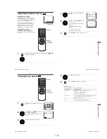
Symptoms caused by contaminated video heads
• Normal picture
• Unclear picture
• Rough picture
initial
contamination
terminal
• No picture (or
black & white
screen appears)
104
Index to parts and controls
Index to parts and controls
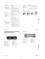
Refer to the pages indicated in parentheses ( ) for details.
Front panel
A
?
/
1
(on/standby) switch (10) (32)
B
Disc tray (27)
C
A
(open/close) button (27) (28)
D
Tape compartment (31)
E
A
(eject) button (32)
F
LINE-2 IN
t
/
o
L/R jacks (92)
G
SELECT DVD/VIDEO (9)
H
z
REC (record) button (35)
I
P/– buttons (35)
J
Display window (28) (31)
K
Remote sensor
L
m
(rewind)/
M
(fast-forward) button
(28) (32)
M
x
(stop) button (28) (32)
N
X
(pause) button (28) (32)
O
H
(play) button (28) (31)
105
Index to parts and controls
Ad
d
itiona
l In
fo
rm
ation
Display window
A
DVD indicator (28)
B
Disc indicator (28)
C
Playing time/clock/current status
indicator (28)
D
Tape indicator (31)
E
VCR indicator (31)
F
RECORD indicator (35)
G
TIMER indicator (40)
H
STEREO indicator (84)
I
CHAPTER indicator
J
TITLE indicator
K
DTS indicator (53)
L
SURROUND indicator (74)
continued
Summary of Contents for SLV-D900E
Page 39: ...3 Block Diagram 3 2E 3 1 SLV D900E D900G ...
Page 41: ...4 3 4 4 4 1 VCR Main COMPONENT SIDE ...
Page 42: ...4 6 4 5 CONDUCTOR SIDE ...
Page 43: ...4 7 4 8 4 2 DVD Main CONDUCTOR SIDE COMPONENT SIDE ...
Page 44: ...4 10E 4 9 4 3 FUNCTION Timer COMPONENT SIDE CONDUCTOR SIDE ...
Page 47: ...5 6 5 5 5 1 S M P S ...
Page 48: ...5 8 5 7 FROM TO DVD Audio Video CN4 5 2 Power Drive ...
Page 49: ...5 10 5 9 5 3 OSD VPS PDS ...
Page 50: ...5 12 5 11 5 4 NICAM ...
Page 51: ...5 14 5 13 5 5 A V ...
Page 52: ...5 16 5 15 5 6 Hi Fi ...
Page 53: ...5 18 5 17 5 7 Input Output ...
Page 54: ...5 20 5 19 5 8 TM ...
Page 55: ...5 22 5 21 5 9 SYSCON ...
Page 56: ...5 24 5 23 5 10 DVD Main Micom AV Decoder ...
Page 57: ...5 26 5 25 5 11 DVD Servo ...


