2-5
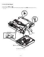
2-2-3 Housing Ass’y Removal
1) Remove Belt
1
.
2) Push the Hook
2
in the direction arrow “A” and lift up Pulley Gear
3
.
3) Push the Slider Housing
5
in the direction arrow “B” and lift up the Gear Tray
4
.
4) Lift up the Slider Housing
5
.
5) Remove the soldering
6
of 2 points (Red, Black).
6) Remove 2 Screws
7
and lift down the Motor Load Assy
8
.
7) Push the 2 Hooks
9
bottom side in the direction arrow “C” and lift up the Housing PCB
0
.
8) Push the Hooks
qa
and remove Deck PCB
qs
.
Fig. 2-9 Housing Ass’y Removal
1
BELT
3
PULLEY GEAR
4
GEAR TRAY
8
MOTOR LOAD ASSY
9
3 HOOKS
0
HOUSING PCB
qa
HOOK
6
SOLDERING
7
2 SCREWS
5
SLIDER HOUSING
2
HOOK
"A"
"B"
<Bottom Side>
"C"
"C"
"C"
Summary of Contents for SLV-D900E
Page 39: ...3 Block Diagram 3 2E 3 1 SLV D900E D900G ...
Page 41: ...4 3 4 4 4 1 VCR Main COMPONENT SIDE ...
Page 42: ...4 6 4 5 CONDUCTOR SIDE ...
Page 43: ...4 7 4 8 4 2 DVD Main CONDUCTOR SIDE COMPONENT SIDE ...
Page 44: ...4 10E 4 9 4 3 FUNCTION Timer COMPONENT SIDE CONDUCTOR SIDE ...
Page 47: ...5 6 5 5 5 1 S M P S ...
Page 48: ...5 8 5 7 FROM TO DVD Audio Video CN4 5 2 Power Drive ...
Page 49: ...5 10 5 9 5 3 OSD VPS PDS ...
Page 50: ...5 12 5 11 5 4 NICAM ...
Page 51: ...5 14 5 13 5 5 A V ...
Page 52: ...5 16 5 15 5 6 Hi Fi ...
Page 53: ...5 18 5 17 5 7 Input Output ...
Page 54: ...5 20 5 19 5 8 TM ...
Page 55: ...5 22 5 21 5 9 SYSCON ...
Page 56: ...5 24 5 23 5 10 DVD Main Micom AV Decoder ...
Page 57: ...5 26 5 25 5 11 DVD Servo ...


