background image

133

To make settings:
In Edit Mode on the SLOT STATUS page, when the
slot to which a DMBK-R109 is inserted is selected,
you can set the format for the MADI output signal on/
off function.
• Format pattern
• Word clock

Proceed as follows to make settings.

1

To set Format Pattern, click either the [LEGACY]
or the  [2FS] radio button, and to set word clock,
click either the [1/1] or the [1/2] radio button.

2

Click the [APPLY] button.

To change OUTPUT STATUS:
See “To make the settings” on page 132 for the
DMBK-R103.

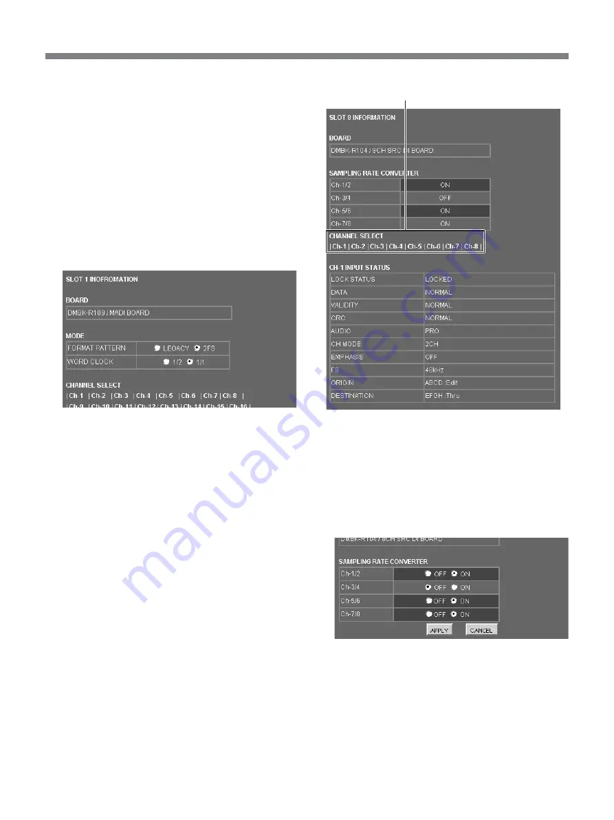
DMBK-R104

When the slot into which the DMBK-R104 is inserted
is selected you can confirm the channel status, and in
Edit Mode, you can set the sampling converter on/off
function.

To confirm the channel status:
Click the channel number in the CHANNEL SELECT
column.

Click the desired channel number.

To set the sampling channel converter to on or off
In Edit Mode, for 4 groups, channels 1 and 2, channel
3 and 4, channels 5 and 6, and channels 7 and 8, you
can set the sampling rate converter function on/off
respectively.

1

Click the [ON] or [OFF] radio button for each
channel group.

A column where the current setting is ON is
displayed in a darker color than ones where the
current setting is OFF.

2

Click the [APPLY] button.

Summary of Contents for SIU-100

Page 1: ... かたを示してあります この取扱説明書をよくお読みのうえ 製品を安全 にお使いください お読みになったあとは いつでも見られるところに必 ず保管してください 3 748 121 01 1 付属のCD ROMには 本機の取扱説明書 日本語 英語 フランス語 ド イツ語 イタリア語 スペイン語 中国語 がPDFデータ形式で入ってい ます 詳しくは CD ROM取扱説明書を読む 12ページ をご覧くださ い The supplied CD ROM includes operating instructions Japanese English French German Italian Spanish and Chinese versions in PDF format For details see Using the CD ROM Manual on page 87 ...

Page 2: ...や費用については ソニーのサービス担当者または営業担当者 にご相談ください 故障したら使用を中止する ソニーのサービス担当者 または営業担当者にご連絡ください 万一 異常が起きたら 1 AC電源コードを抜く 2 ソニーのサービス担当者 または営業担当者に修 理を依頼する すぐにAC電源コードを抜き 消火する 異常な音 に おい 煙が出 たら 炎が出たら 警告表示の意味 この取扱説明書および製品で は 次のような表示をしていま す 表示の内容をよく理解して から本文をお読みください この表示の注意事項を守らない と 火災や感電などにより死亡 や大けがなど人身事故につなが ることがあります この表示の注意事項を守らない と 感電やその他の事故によりけ がをしたり周辺の物品に損害を与 えたりすることがあります 注意を促す記号 行為を禁止する記号 行為を指示する記号 ...

Page 3: ...MP マイ クアンプ メニュー 37 SETUP セッ トアップ メニュー 38 パーソナルコンピューターでの各種設定 50 必要な機器 50 準備 50 System Interface Unitプログラムの起動と終了 50 TOPページの画面構成 51 Routingページ 53 Slot Statusページ 56 SYNCページ 60 SCENEページ 61 MIC AMPページ 63 MIDIページ 64 リモートコントロールユニットSIU RM101 別売り の操作 66 概要 66 各部の名称と働き 66 電源を入れる 68 DMBK S101 別売り をリモー トコン ト ロールする 68 仕様 70 その他 71 本機の性能を保持するために 71 エラーメ ッセージ 71 仕様 72 システムイ ンターフェースユニッ ト SIU 100 100T 72 REMOTE端子の仕...

Page 4: ...ビス担当者または営業担当者にご相談くだ さい 電源コードを傷つけない 電源コードを傷つけると 火災や感電の原因と なり ます 電源コードを加工したり 傷つけたり しない 重いものをのせたり 引っ張ったり しない 熱器具に近づけたり 加熱したり しない 電源コードを抜く ときは 必ずプラグを持って 抜く ラ ッ クマウン トすると きは レールにはさみ込ま ない 万一 電源コードが傷んだら ソニーのサービス 担当者に交換をご依頼 ください 油煙 湯気 湿気 ほこりの多い場 所では設置 使用しない 上記のような場所で設置 使用すると 火災や 感電の原因となり ます 表示された電源電圧で使用する 機器に表示されたものと異なる電源電圧で使用 すると 火災や感電の原因となり ます 安定した場所に設置する 製品が倒れたり 搭載した機器が落下してけが をすることがあり ます 十分な強度がある水平な場所に...

Page 5: ...し 変換 プラグから出ている緑色のアースを建物に備え られているアース端子に接続する 安全アースを取り付けるこ とができない場合は ソニーのサービス担当者にご相談ください 定期的に内部の掃除を依頼する 長い間 掃除をしないと内部にホコ リがたまり 火災や感電の原因となるこ とがあり ます 1年に 1度は 内部の掃除をお買い上げ店またはソ ニーのサービス窓口にご依頼く ださい 有 料 特に 湿気の多くなる梅雨の前に掃除をする と より効果的です 移動の際は電源コ ードや接続コー ドを抜く コード類を接続したまま本機を移動させると コードに傷がついて火災や感電の原因となるこ とがあり ます お手入れの際は 電源を切る 電源を接続したままお手入れをすると 感電の 原因となることがります 接続の際は電源を切る 電源コー ドや接続コー ド を接続すると きは 電源 を切ってく ださい 感電や故障の原...

Page 6: ...損害を与えることがあります 6 48V外部電源駆動方式のマイク以 外は 48Vに設定しない 48Vの外部電源駆動方式以外のマイ クを接続 したチャンネルで 48V スイ ッチを入れて 使用すると マイ クを破損する原因となり ます オプション基板の 取り付けは依頼 する オプショ ン基板の取り付けは お買い上げ店ま たはソニーのサービス窓口に相談ください 底面の通気孔をふさがない 平らなところにおいて使用する場合は 底面の 足をはずさないでください ...

Page 7: ... 48V電源のOn Offな どの外部制御が可能です DMX R100 別売り の入出力チャンネル数の拡張に最適 DMX R100とSIU 100 100Tの両方にMADI基板DMBK R109 別 売り を装着することで48チャンネルの信号が相互に伝送できま す SIU 100 100Tを通じてDMX R100の入出力数を最大48チャン ネル拡張できます 8チャンネルマイクプリアンプ基板DMBK S101 別売り で マイク入力チャンネルを拡張 リモートコントロールユニッ トSIU RM101 別売り でDMBK S101遠隔操作が可能 SIU 100 100Tには DMBK S101を最大7枚まで装着可能で マイ ク入力を最大56チャンネルに拡張できます マイ クプリアンプ部のレベルの調節や 48V電源のオン オフの設 定を SIU 100 100T本体で外部制御可能です さらにDMB...

Page 8: ...スターとし SIU 100 100Tのワードシンク出力にDMX R100を同期させれば DMX R100ミキサーシステムをHDビデオ 機器の環境下で使用すること も可能になり ます パーソナルコンピューターを使用したコントロール操作 イーサネッ ト端子 10BASE T の装備により Windows 1 または Macintosh 2 パソコンと接続することができます SIU 100 100Tは HTTPサーバーを内蔵していますので パーソナルコンピューター のイ ンターネッ ト ブラウザ を使用して 特別な制御ソフ トなしで各 種設定が可能です リダンダント電源仕様 SIU 100Tのみ SIU 100Tは独立した2つの電源ユニッ ト を装備しています どちら か一方の電源ユニッ トやAC電源ライ ンが故障しても も う一方の電 源で動作を続けることができます SIU 100も 電源ユニ...

Page 9: ...ディオミキサーシステムの入出力拡張 スピーカー パワーアンプ スピーカー パワーアンプ SIU 100 100T キーボード ギター マイクロホン DMX R100 DMBK R109 MADI SIU RM101 同期信号発生器 ハブ イーサネット パーソナルコンピューター DMBK S101 DMBK R101 DMBK R102 DMBK R109 DMBK S101 DMBK S101 DMBK R101 DMBK R102 別売り基板 アンプなど ...

Page 10: ...のシェアリング SIU 100 100T キーボード デジタルオーディオワークステーション マイクロホン DMX R100 DMBK R109 MADI SIU RM101 ハブ パ ー ソ ナ ル コ ン ピューター 同期信号発生器 ブース1 コントロール ルーム1 ブース2 コントロール ルーム2 SIU 100 100T キーボード デジタルオーディオワークステーション マイクロホン DMX R100 MADI SIU RM101 パーソナルコン ピューター MTR MTR ...

Page 11: ...11 構成例3 フォーマット変換と信号のルーティング SIU 100 100T マイクロホン SIU RM101 デジタルオーディオワークステーション TDIF ADAT MADI またはAES EBU CDプレーヤー DMBK S101 DMBK R106 DMBK R107 DMBK R109 DMBK S101 DMBK R103 MTR 別売り基板 ...

Page 12: ...Netscape社の ホームページからダウンロード してご利用ください 無料でダウ ンロードできます http home netscape com ja downloads index html 1 MMXおよびPentiumは 米国Intel Corporationの米国およびその他の国における登録商標です 2 Power PCは International Business Machines Corporationの登録商標です 3 Microsoftは 米国Microsoft Corporationの米国およびその他の国における登録商標です 4 Netscape Navigatorは 米国Netscape Communications Corporationの米国およびその他の国における登録商標です 5 AdobeおよびAcrobatは Adobe Systems Incorpora...

Page 13: ...になり ま す SIU 100Tの場合 いずれか一方の電源スイ ッチを入れると起動 し 電源をリダンダン ト動作させる場合は A B両方の電源を 側にします ご注意 周辺機器を接続するときは 必ず電源を切ってから行ってくださ い ご購入後数年以上経過すると 内部のバックアップ用バッテリー が消耗し 前回電源を切ったと きの状態を再現できなくなり ます この場合は Backup Error の表示を出すと と もに 前回シーンを 保存したと きにシステムがバッ クアップと して不揮発性メモリーに 保存した状態で起動します 詳しくは エラーメ ッセージ 71ページ をご覧ください 2 LCD 液晶 ディスプレイ 通常は SIU 100 100TのSYNCの状態 サンプリ ング周波数 同 期基準信号の選択状態など を表示します 通常の表示内容の詳細については LCD 液晶 ディ スプレイ 通常 ...

Page 14: ...スロッ トの8つのチャン ネルのレベルメーターになり 縦1列が1つのチャンネルを表示しま す メーターの表示の色はユーザーの設定したス レ ッ シ ョル ド レベ ルに応じて緑と赤の2段階で表示されます STATUSモード METERモードについて INPUTモニターディ スプレイ部のイ ンジケーターは STATUSまた はMETERのいずれかの状態で表示されます 表示モードの選択 とLEDの点灯するスレッショルドレベルの設定はSETUPメニュー のLED DISPLAYサブメニューで操作します 詳しくは INPUTモニターディ スプレイ を設定するには 41ページ をご覧ください ご注意 レベル表示は入力の機能のある基板を装着しているスロッ トのみ 行います 出力の機能のみの基板8チャンネルアナログライン出力基板 DMBK R102についてはレベル表示は行いません MADI基板DMBK ...

Page 15: ...出力チャンネルを接 続するルーティ ング設定を行うメニューを表示します SLOTボタン スロッ ト単位でルーティ ングを設定するときに使用 します CHECKボタン ルーティ ング設定の確認をするときに使用しま す 2 SCENE シーン ボタン SCENEメニューを表示します シーンのRECALL 呼出し やSTORE 保存 などを行います 3 PHONES ヘッドホン ボタン ヘッ ドホン設定画面を表示します ヘッ ドフォン端子でモニターするチャンネルを設定します 4 SETUP セットアップ ボタン ROUTING SCENE MIC AMP PHONESメニューで行う設定以 外の各種設定を行うSETUPメニューに入り ます 5 MIC AMP マイクアンプ ボタン マイ クプリアンプボードDMBK S101を装着している場合に パラ メーター設定画面を表示します マイ クプリ アン...

Page 16: ...DEO WORD 入力信号選択 スイッチ ワードクロックとビ デオ信号のどち らを入力するかを選択します SETUPメニュー のSYNCサブメニューで選択されている同期基準の種類と合 わせます IN 入力 端子 BNC型 外部機器と同期をとるためのワードシ ンク信号またはビデオ信号を入力します 入力される信号は VIDEO WORD 入力信号選択 スイ ッ チで切り換えます 通常75Ωで終端されていますが THRU端子にコネクターが接 続されると 75Ω終端は解除されます THRU スルー 端子 BNC型 IN端子のループスルー出力 です この端子にコネクタが接続されていると IN端子の75Ω 終端は解除されます 2 REF WORD 基準ワードシンク信号出力 端子 BNC型 SIU 100 100Tが動作しているサンプリ ング周波数に同期したワー ドシンク信号を出力します 3 U アース...

Page 17: ...1 2にのみ装 着でき 最大2枚が使用でき ます それ以外のスロ ッ トには装着でき ません 別売り基板については19ページをご覧ください スロッ ト番号は下図のとおりです LCD 液晶 ディスプレイ ー 通常画面について メニュー操作以外の場合の通常画面の表示について説明します 1 SYNC設定状態表示部 SETUPメニューで設定した 同期基準クロック と動作サンプリ ング 周波数の選択の状態を表示します 2 PLL動作状態表示部 SIU 100 100T内部のPLLの動作状態を表示します LOCK 正常に動作しています UNLOCK 同期が取れていません 設定に合った同期信号が正 しく入力されているかど うか確認してください NO REF WORD NO REF DI NO REF VIDEO 必要な 外部同期信号が入力されていません 後面パネルのVIDEO WORDスイ ッチが正しく...

Page 18: ...18 各部の名称と働き INTERNAL設定の場合の表示例 EXT WORDとEXT DI設定の場合の表示例 正常な場合 同期が取れていない場合 同期信号が入力されていない場合 EXT VIDEO設定の場合の表示例 正常な場合 ビデオ信号への同期が取れていない場合 同期ビデオ信号が入力されていない場合 ...

Page 19: ...は 8チャンネルマイ クプリアンプ基板DMBK S101 別売り 24ページ をご覧ください 仕様 入力端子 XLR 3 31 メス 8 平衡 ピン配列 1 GND 2 HOT 3 COLD 基準入力レベル 4dBu 最大入力レベル 24dBu 入力イ ンピーダンス 10kΩ 8チャンネルアナログライン出力基板DMBK R102 1 ANALOG OUTPUT アナログ信号出力 端子 バランスのアナログ信号 4dBu基準 を出力します 仕様 出力端子 XLR 3 32 オス 8 平衡 ピン配列 1 GND 2 HOT 3 COLD 基準出力レベル 4dBu 負荷イ ンピーダンス10kΩ 最大出力レベル 24dBu 負荷イ ンピーダンス10kΩ 出力イ ンピーダンス 150 Ω 8チャンネルアナログライン入力基板DMBK R101 ...

Page 20: ...ター基板DMBK R104 1 SAMPLING RATE CONVERTER DI オプティカル デジタルオーディオ信号入力 端子 XLR オプティカルタ イプ AES EBU信号または民生用CDプレーヤーなどのオプティ カルデ ジタルオーディ オ信号を入力します SETUPメニューのSLOT INFOサブメニューで サンプリ ングレー トコンバーターの機能のON OFFを設定することができます ご注意 XLRコネク ターとオプティ カルコネク ターを同時に使用するこ とは できません どちらか一方だけを機器に接続してください サンプリ ングレート コンバーターの入力周波数の上限は 56kHz までとなっていますので 88 2 96kHzの信号を44 1 48kHzに変 換することはできません SIU 100 100Tのサンプリ ング周波数を88 2 96kHzに設定したと きは 自動的...

Page 21: ...配列 ス リーブ GND チップ 出力 SEND リ ング 入力 RETURN 基準入出力レベル 0dBu 負荷イ ンピーダンス10kΩ 最大入出力レベル 20dBu 負荷イ ンピーダンス10kΩ 出力イ ンピーダンス 150Ω 入力イ ンピーダンス 10kΩ ADAT用インターフェース基板 DMBK R106 仕様 端子 角型光コネクター 2 ADATイ ンターフェース1 を持ったテープレコーダーなどの外部機 器を接続します ご注意 SIU 100 100Tまたは入力信号のサンプリング周波数が88 2 96kHzのときには動作しませんのでご注意ください 1 ADATは ALESIS STUDIO ELECTRONICS INC 社のイ ンターフェイ スの登録商標です ...

Page 22: ...してくだ さい 詳しくは スロッ トの確認 設定をするには 41ページ および DMBK R107の場合 59ページ をご覧ください 仕様 端子 D SUB 25ピン メス MADI基板DMBK R109 1 MODE SELECT モード選択 スイッチ DMBK R019の使用状態を選択します SIU 100 100Tに装着する場合は 必ずMADIに設定します MASTER SUBモードは ソニーのデジタルミ キサーDMX R100に 装着して使用する場合の専用の特殊なモードです SIU 100 100Tに装着する場合は これらのモードでは 正常に動作しませ ん ご注意 MODE SELECTスイ ッチの設定は 必ずSIU 100 100Tの電源を 入れる前に行ってください DMX R100とMADI接続する場合は DMX R100 SIU 100 100T 両方に本基板を装着し 両基板...

Page 23: ...ICAL にすると このIN端子 にFDDIフォーマッ トのAES 10準拠のMADI信号を入力することが できます OUT端子からはBNC型のOUT端子2と同じMADI信号が同時に 出力されます 5 WORD SYNC ワードシンク信号 端子および75Ωス イッチ 外部機器と同期をとるためにワード信号を入出力するための端子 です IN端子 ワードシンク信号を入力します 75Ωスイッチ 終端抵抗をON OFFします ワ ドシンク信号を使用する場合は このスイ ッチを正しく設 定する必要があり ます 通常は ONに設定します T型BNC中 継コネク タを使用して他の機器にワード シンク信号を分配する 場合はOFFに設定します OUT端子 ワードシンク信号を出力します ご注意 SIU 100 100TをDMBK R109のWORD SYNC IN端子に入力した ワードシンク信号に同期させるとき...

Page 24: ...正常に動 作しなくなる場合があり ます 例 消費電流が10mAのマイク2本と3mAのマイクを6本を 1つのDMBK S101に接続する場合は 合計38mAですので問題あり ません 仕様 入力端子 XLR 3 31 メス 8 平衡 ピン配列 1 GND 2 HOT 3 COLD 基準入力レベル 66dBu 10dBu 2dB単位 最大入力レベル 24dBu マイ ク電源 48V オン オフ PADレベル 30dB オン オフ マイ クE I N 126dB 最大ゲイ ンレベル時 150Ω終端 サンプリ ング周波数 44 1 48 88 2 96kHz 12 5 ダイナミ ックレンジ 104dB ライ ンレベル時 SIU 100 100T専用の8チャンネルマイ クプリアンプ基板です SIU 100 100Tに装着した状態でレベルや 48V電源のオン オフなど 外部からの制御が可能となります 装...

Page 25: ...ロッ ト8 8チャンネルアナログライ ン出力基板DMBK R102 マイク DMBK S101へ a DMBK R109へ b DMBK R109へ スロット4に装着 b DMX R100 MIDI OUT端子へ REF WORD OUT端子へ REF WORD IN 端子へ MIDI IN端子へ c REMOTE IN端子へ モニタースピーカー パーソナルコンピューター REMOTE OUT端子へ SIU RM101 REMOTE IN端子へ REMOTE OUT端子へ SIU RM101 REMOTE IN端子へ REMOTE OUT端子へ SIU RM101 e MIDI IN端子へ c 1 2 3 4 5 1 2 a 図中のa e については 次ページ 接続図 中の脚注について をご覧ください b 図中の1 5については 次ページの 接 続コードについて をご覧ください DMBK ...

Page 26: ...してください 接続例では SIU 100 100TおよびDMX R100に装着されてい るDMBK R109の接続に BNC型のMADI端子が使用されて います c SIU RM101を接続している場合 DMX R100からのMIDI信号 は SIU 100 100TかSIU RM101のどちらか一方に接続してく ださい d SIU 100 100Tのイーサネッ ト端子には パーソナルコンピュー ターを直接接続する場合は クロスケーブルを ハブなどを介 して接続する場合は ス ト レー トケーブルを使用してください e SIU RM101は 最大7台までカスケード接続できます 接続コードについて 接続例で使用する接続コードは以下のとおりです 図中では 各接続コードには 1 5と番号が振られています 番号 接続ケーブル 1 キャノンケーブル 2 75Ω同軸ケーブル 3 MIDIケーブル 4 ...

Page 27: ... MIC AMP PHONES SETUP メニュ 操作 第 3 章 メ ニ ュ ー の 構 成 システムの設置と接続が終わったあとは 必要に応じて各種設定 を行います 設定方法には SIU 100 100T本機の前面パネルで行う方法と パーソナルコンピューターから行う方法の2通りあり ます ここでは 前面パネルのボタンを使用してのメニュー操作について 説明します パーソナルコンピューターから行う方法について詳しくは パーソナ ルコンピューターでの各種設定 50ページ をご覧ください メニュー構成 本機のメニューは次のように構成されています 詳しい内容は 内のページをご覧ください 通常の画面 ROUTINGメニュー 28 ROUTING サブメニュー SCENEメニュー 31 MIC AMPメニュー 37 PHONESメニュー 36 SETUPメニュー 38 SETUPサブメニュー ...

Page 28: ...接続確認マークは自動的に変わり ます カーソルを移動させるには V v B bボタン も しくはINPUTボタン OUTPUTボタンで行い ます INPUTボタンはVボタンと OUTPUTボタンはvボタンと同じ 意味になり ます カーソルがINPUT側 上段 に表示されている場合はINPUTボタン のLEDが点灯し カーソルがOUTPUT側 下段 に表示されている 場合はOUTPUTボタンのLEDが点灯します スロット番号 チャンネル番号を変更するには 数字ボタン ボタンを押して そのときカーソルのある部分の スロッ ト番号も しくはチャンネル番号を変更します ROUTINGメニューから抜けるには INPUTボタンまたはOUTPUTボタンのどちらかLEDの点灯してい る方を押します ルーティングに関する注意 ルーティ ングされていない出力チャンネルには 無音状態 デジ タ リーゼロ が出力...

Page 29: ...れている場合 接続確認マークが と の点滅表示になり ます この場合は操作を続行するとそ れまでのルーティ ングが解除され 新しく指定したルーティ ン グに変更されることになります 点滅表示 3 ENTERボタンを押す ルーティ ングが確定します 接続しない場合は ENTERボタンを押す代りにCANCELボタンを押します チャンネルごとのルーティングを解除するには すでに接続されている入力チャンネルと出力チャンネルを指定して ルーティ ングを解除します 1 INPUTボタン OUTPUTボタン V v B bボタン テンキー ボタンを使って 解除したい入力および出力チャンネル を表示させる または CHECKボタンを使って チャンネルごとのルーティ ングを確認するには 30ページ の手順1 2の操作を行 う 解除したい接続状態を表示させる 2 CROSS POINT OFF CANCEL ...

Page 30: ...3 続けて確認する場合はCHECKボタンを押しながら B または bボタンを押す 手順2で確認した以外のルーティ ングを順番に確認するこ とが でき ます B またはbボタンを押すごとにカーソルのある側 入 力も しくは出力 のチャ ンネルを前 または次の順に切り換えな がら それと対応する接続を検索し 表示します 1つの入力チャンネルに接続されている複数の出力チャンネ ルを確認する場合にも便利です bボタンを押すごとに 若い 番号順で接続されている出力チャンネルが表示されます スロット 8チャンネル 単位のルーティングを設 定するには スロッ ト全体の8チャンネルを単位と して取り扱ったルーティ ング操 作ができます 1回の操作で 入力側のスロッ トのチャンネル1から 8が出力側スロッ トのチャンネル1から 8にそれぞれルーティ ングさ れます ご注意 MADI基板DMBK R109につ...

Page 31: ...POINT ONボタンを 押したとき の接続確認マークが表示されます スロッ ト設定モードで設定したルーティ ングをチャンネルごとの設 定で変更することも可能です スロッ ト設定モードでのルーティ ングの接続確認は 8つのチャ ン ネルがすべて対応しているかど うかで検索します 8つのチャン ネルすべてが接続されていなければスロッ ト設定モー ドでは確認 できません スロッ ト 8チャンネル 単位での設定がされていないスロッ トに対 してスロッ ト設定モードで接続解除の操作はできません SCENE シーン メニュー 以下の情報をシーンと して最大255個まで保存しておく ことができ ます シーン番号 シーン名 I Oルーティ ングマ ト リ クスの設定状態 別売り基板8チャンネルマイ クプリ アンプ基板DMBK S101のレベ ル 48V PADの設定状態 SYNCサブメニューの設定状態 ...

Page 32: ...保存されているか ど うかを表示します シーンが保存されていない場合 空白になり ます シーンが保存されている場合 ピリオ ド が表示されます 現在使用中のシーン番号の場合 が表示されます 4 プロテクトマーク 選択したシーンがプロテク ト されているかどうかを表します シーンがプロテク ト されていない場合 空白になり ます シーンがプロテク ト されている場合 P の文字が表示されます サブメニューを選択するには 1 SCENEボタンを押す SCENEボタンのLEDが点灯し SCENEメニューに入り ます 2 B bボタンでサブメニューを選択する サブメニュー名がRECALL y STORE y DELETE y PROTECT y ISOLATEの順番に表示されます 3 選択するメニューの表示が出たらENTERボタンを押す SCENEメニューを終了するには SCENEボタンを押します...

Page 33: ...存 するときのシーン名を編集できる状態になり ます 名前を編集しない場合は そのまま手順5に進みます 名前を編集する場合は 以下のボタン操作で名前を入力しま す 4 選択したシーンに名前をつける シーン名は最大15文字です 文字を入力する箇所を決めるには B bボタンでカーソルを 移動させます 入力文字を選択するには ボタンで選択します 数字を入力するには テンキーで直接入力でき ます ボ タンでも選択できます 空白 vボタンで空白を直接入力でき ます ボタンでも選 択できます 入力できる文字 アルファベッ トの小文字 大文字 a b c d e f g h i j k l m n o p q r s t u v w x y z A B C D E F G H I J K L M N O P Q R S T U V W X Y Z 記号 空白 5 ENTERボタンを押す シーン番号とシーン...

Page 34: ...CELボタンを押します CANCELを押すと2の状態に戻り ます 音切れについて シーン呼び出し操作を行っても サンプリ ング周波数の変更がない 場合で シーン呼び出しの前後で同じルーティ ングの部分につい ては 音切れは発生しません 保存されているシーンを削除するには 1 DELETEサブメニューに入る 2 ボタン テンキーで削除するシーンの番号を入力する シーンが保存されている番号のみが選択可能です 3 ENTERボタンを押す 確認の意味の マークが表示されます ご注意 プロテクトが 設 定され て い るシ ー ン 番 号 を 選 ぶと Protected と表示され 削除できません 4 削除してよければもう一度ENTERボタンを押す 削除が終了すると 約2秒間 Completed と表示されます 削除が実行された直後は 削除したシーン番号が表示された ままになり ます 削除を中止す...

Page 35: ...pleted と表示されます 操作を中止するには CANCELボタンを押します CANCELを押すと2の状態に戻り ます アイソレート機能を設定するには アイ ソレート機能を設定しておく と シーンを呼び出すときに再現 される部分を制限することができます アイ ソレート設定は 個々のシーンに対する設定ではなく どの シーンを呼出す場合にも共通の設定です また アイ ソレート した 機能は シーン呼出時の再現は禁止されますが シーンを保存す る時にはそのと きの設定状態がシーンの情報と して記録されます 以下の情報がアイ ソレート設定可能です I Oルーティ ングマ ト リ クスの設定状態 DMBK S101のレベル 48V電源 PADの設定 SYNCの設定情報 SLOT INFOメニューの設定 DO CH STATUSメニューの設定 これらはこれ以上細かく分解しては設定できません 1 IS...

Page 36: ...ている チャンネルに切り換わり ます MIC AMPメニュー表示時 設定しているチャンネルに切り換 わり ます それ以外の時 最後にモニターしたチャンネルをそのま まモニ ターします STEREOモードとMONOモードに STEREO ST モード 連続した奇数番号と偶数番号の2つのチャンネルをステレオのペ アとみなして 左 L 右 R のモニターに音を出します MONO ヘッ ドホンの左 L と右 R に同じチャンネルの音を出力します PHONESメニューの画面構成 1 モード表示 モードを表示 選択します 2 モニターチャンネル表示 モニターしているチャンネルを表示 選択します 表示 選択する内容は INPUT OUTPUTの区別 スロッ ト番号と チャンネル番号です モニターするチャンネルを選ぶには 1 PHONESボタンを押す PHONESボタンのLEDが点灯し PHONESメニュ...

Page 37: ...ます 3 PAD表示 PADのON OFFの表示 選択を行います 4 基準入力レベル表示 基準入力レベルの表示 選択を行います DMBK S101の設定を行うには 1 MIC AMPボタンを押す MIC AMPボタンのLEDが点灯し MIC AMPメニューに入り ます 2 ボタン テンキーで設定を行うスロッ ト とチャンネルを上 段のスロッ ト SL とチャンネル CH で指定する 指定したチャンネルの設定状態が表示されます 3 V v B bボタンでカーソルを移動し テンキー ボタン で値も しくは状態を変更する 48V電源のON OVV 48Vの表示にカーソルを移動し ボタンでON FFを切 り換えます PADのON OFF PADの表示にカーソルを移動し ボタ ンでON OFFを切 り換えます 基準入力レベルの調整 LVLの表示にカーソルを移動し 以下のいずれかの操作で設 定します ...

Page 38: ...り ます SYNC 本機の動作サンプリ ング周波数 同期基準信号の選択を行いま す LED DISPLAY 前面パネル上のINPUTモニターディ スプレイの表示モードの設 定などを行います SLOT INFO 後面パネルのスロッ トに装着されている別売り基板の種類を表示 します 基板の種類によっては その基板の動作の設定を行いま す DI LOCK STATUS AESデジタル入力を持つ別売り基板使用時に 入力信号のロ ッ ク 状態を表示します DI CH STATUS AESデジタル入力を持つ別売り基板使用時に 入力信号のチャ ンネルステータスの詳細を表示します DO CH STATUS AESデジタル出力を持つ別売り基板使用時に 出力するチャンネ ルステータスに関する設定を行います MIDI MIDI入力によるシーン呼出しに関する設定を行います IP イーサネッ ト端子を使う場合の本機...

Page 39: ... どの信号を基準とするかもあわせて指定します EXT WORD リ アパネルのREF WORD REF VIDEO端子に入力されたワード クロックに同期します ご注意 EXT WORDを選択した場合は リ アパネルのVIDEO WORD切 り換えスイ ッチをWORD側に設定する必要があり ます EXT VID EO リ アパネルのREF WORD REF VIDEO端子に入力されたビデオ 信号に同期します ご注意 EXT VIDを選択した場合は リアパネルのVIDEO WORD切り 換えスイ ッチをVIDEO側に設定する必要があり ます 入力するビ デオ信号の垂直同期周波数をあわせて指定します サンプリング周波数について 44 1kHz 47 952kHz 48kHz 88 2kHz 96kHzの中から選択しま す サンプリング周波数のAUTO指定について EXT WORDかEXT DIを...

Page 40: ...ることを表してしています 手順2 3で設定を変更するとマークが消えるため SYNCの設 定を変更しよう と していることがわかり ます 2 同期基準信号を選択する カーソルを下段に移動し ボタンで希望の同期基準を表 示させます 同期基準は INTERNAL y EXT DI y EXT WORD y EXT VIDの順に切り換わり ます EXT DIを選択した場合は bボタンでカーソルを右に移動してソースチャンネルを指定し ます EXT VIDを選択した場合は bボタンでカーソルを右に移動してビデオの周波数を指定しま す 3 サンプリ ング周波数を設定する カーソルを上段に移動し ボタンでサンプリ ング周波数 を指定します 4 ENTERボタンを押す 確認のために マークが表示されます 5 変更を実行してよければENTERボタンを押す 内部の処理が完了すると マークが マークになり ます ...

Page 41: ...EDが緑色に点灯します METERモードの場合はこのTH GRNの設定は関係あり ませ ん ご注意 通常は赤色のレベルを緑色より高く設定して 消灯 t 緑点 灯 t 赤点灯の順番で点灯させます 赤色のレベルを緑色よ り も低く設定すると 消灯 t 赤点灯の2段階になります SIU RM101を接続して使用する場合 ここで設定したLEDが点灯するレベルは SIU RM101のパネル上 のSIGNAL OVERイ ンジケーターの点灯にも適応されます スロットの確認 設定をするには SLOT INFOサブメニューで各スロッ トに搭載されている基板の種 類の確認 設定などを行います SLOT INFOサブメニュー画面の構成 1 SLOT番号 スロッ ト番号を表示 選択します 2 基板 基板の種類を表示 選択します 基板の種類によっては さ らに各 種設定を表示 選択します 基板の確認をするには 1...

Page 42: ...ます WCK DMBK R109のWORD SYNC OUT端子に入出力さ れるワードクロックの周波数と して1 1 1 2のいずれかを指 定します 1 1の場合通常のワードクロック周波数になり 1 2の場合 周波数が1 2のワードクロックになり ます bボタンでカーソルをあわせて ボタンで選択します ご注意 OUT WCKいずれも 出力信号の設定で 入力信号の フォーマッ ト ワードクロックは自動認識されます デジタル入力信号のロック状態を確認するには 1 DI LOCK STATUSサブメニューに入る 上段にスロッ ト番号と基板の種類が表示されます 2 確認したいスロッ ト番号を ボタン またはテンキーで表示 させる 下段に指定したスロッ トの8つのチャンネルの状態が 左から チャンネル1 8の順に表示します L LOCKの意味 正常に同期した信号を受信していることを 表します U U...

Page 43: ...ァシスされ ていない 本機にはディ エンファシスの 機能はありません 入力され た信号はそのままの状態で ルーティ ングされ出力されま す デジタルオーディ オのサンプ リ ング周波数を表示する NotIndicatedとなる場合もあ る チャンネルステータスに記述 されているORIGIN情報4文 字を表示する チャンネルステータスに記述 されているDESTINATION 情報4文字を表示する スロット番号 チャンネル番号 ステータス情報 表示 1 DI PLL 2 DATA 3 VALIDITY 内容 各入力のPLLのロック状 態を表示する 入力信号と本機の同期 の状態を表示する AES信号のVARIDITYフ ラグの状態を表示する 詳細 LOCK 正常にロックしてい る UNLOCK ロックしていな い この場合は以下の項目 は 表示になり ま す NORMAL 正しく同期して いる ...

Page 44: ...種類を表示します 3 ステータス情報表示 ORIG DEST ORIGIN ステータスのコピー元 DESTINATION ステータスのコピー先 いずれかを選択しま す モード THRU EDITいずれかを選択します データ 選択されたモードにより表示されるものが異なり ます DO CH STATUSサブメニューの操作 1 DO CH STATUSサブメニューに入る 2 設定するスロッ ト とチャンネルを選択する B bボタンでカーソルを移動し ボタン テンキーでス ロッ ト番号とチャンネル番号を指定します 3 設定する項目を選択する V vボタンでORIGINとDESTINATIONを切り換えます カーソルが右のモード設定欄に移り ます 4 ボタンでTHRUモードかEDITモードかを指定する THRUを選択した場合 そのと き自動的にアサイ ン されているデータが右側に表示され ます ED...

Page 45: ... 音声もそのままの状態で ルーティ ングされて出力されます ルーティ ングされている入力 がアナログ信号などで コピーする情報がない場合は OFFに設 定します MIDIに関する設定を行うには SIU 100 100T のMIDI IN端子をDMX R100のMIDI OUT端子と 接続して DMX R100側でスナップシ ョ ッ ト を切り換えたと きに出力 されるMIDI信号 プログラムチェンジメッセージ に反応して SIU 100 100Tのシーンを呼び出すことができます ここではMIDIによるシーンの呼び出しに関する以下の設定を行い ます プログラムチェンジメ ッセージとシーンの対応の設定 プログラムチェンジメ ッセージ受信して実行するMIDIチャンネル の指定 OMNIモードのオン オフ指定 OMNIモード をONに設定した場合 上記のMIDIチャ ンネルの指 定は無視されます ...

Page 46: ... 設定します NAME 本機を識別するためのSIU 100 100Tそれぞれの名前 8文字以 内 を設定します PASSWORD HTTPを使って本機の設定を行う ときのパスワード 8文字以内 を設定します MAC ADDRESS 本機のMACア ドレスを表示します 設定はできません 1 IPサブメニューを表示させる 2 V vボタンで画面を切り換えて 設定したい項目を選ぶ 3 手順2で選んだ項目に関する設定を行う IP ADDRESS GATEWAY SUBNET MASKの設 定 1 B bボタ ンでカーソルを移動させ 4箇所の3桁の数値をテ ンキーで入力する 現在の数値から変えたところが点滅表示になり ます 2 すべて入力したらENTERを押す 確定して点滅がとまり ます NAME PASSWORDの設定 B bボタンでカーソルを移動させ テンキーと ボタンで文 字を入力する アルフ...

Page 47: ...ます 3 vボタンでカーソルを下段に合わせ チャンネル番号を割り当 てる 1 Bボタンでカーソルをスロッ ト番号に合わせ テンキーまた は ボタンでスロッ ト番号を指定する そのときの割り当てられているチャンネル番号が表示され ます 2 bボタンでカーソルを移動し ボタンで手順1で指定 したスロッ トに割り当てるチャンネル番号を変更する 3 手順1と2を繰り返してすべてのDMBK S101基板の表 示チャンネルを設定する SIU RM101メニューを終了するには SETUPボタンを押します SETUPボタンのLEDが消灯し 通常画面に戻り ます 現在の使用状態をすべて消して初期状態に戻すに は SRAM CLEARメニューを使う とルーティ ングの設定をはじめとす るすべての設定を消去して 初期状態に戻すこ とができ ます 使用 中の状態を初期化するだけで 保存しているシーンには影響はあ ...

Page 48: ...参照ください 1 SYSTEM BACKUPサブメニューを表示させる 2 ENTERボタンを押す 確認のための が表示されます 3 ENTERを押す Completed と表示が出ます SIU 100 100Tの動作状態は 変化しません バックアップを止める場合は CANCELを押します バックアップしてある使用状態に戻すには SYSTEM RESTOREメニューを使って SYSTEM BACKUPメ ニュー操作で記憶させた使用状態を再現するこ とができ ます 保存 しているシーンには影響はあり ません 1 SYSTEM RESTOREサブメニューを表示させる 2 ENTERボタンを押す 確認のための が表示されます 3 ENTERを押す Please Reboot と表示が出ます この時点では SIU 100 100Tの動作状態は変化しません バックアップの状態に戻すのを止める場合は C...

Page 49: ...49 ルーティング設定を解除するには ROUTING CLEARサブメニューを使って 現在使用中のルーティ ング設定をすべて解除できます 1 ROUTING CLEARサブメニューを表示させる 2 ENTERボタンを押す 確認のための が表示されます 3 ENTERを押す Completed と表示が出ます 解除を取り消す場合は CANCELを押します ...

Page 50: ... のJavaScript 1 を有効にしておいてください 準備 パーソナルコンピューターから設定を行う際は 以下の設定が必要 です SIU 100 100Tとパーソナルコンピューターを直接接続する場合 は イーサーネッ ト クロスケーブル ハブなどを介して接続する場 合は ス ト レートケーブルで接続します 詳しくは 接続 25ページ をご覧ください SIU 100 100TにIPア ド レスの設定 設定のしかたは IPア ドレスなどを設定するには 46ページ をご 覧ください SIU 100 100Tにパスワードの設定 設定のしかたは IPア ドレスなどを設定するには 46ページ をご 覧ください 設定しない場合は パスワードなしでEdit Modeに入れま す System Interface Unitプログラムの 起動と終了 起動するには 1 パーソナルコンピューターの電源を入れる ...

Page 51: ... Edit Modeでは 状態表示エリアが自動更新されません 4 状態表示エリア SIU 100 100Tにアクセス したときに表示されるTOP ページでは 以下のことが確認できます 現在のUNITに付けられている名前 IPア ド レス シンクの状態 装着されている別売り基板の種類 選択されているページにより 表示内容が異なり ます TOPページに戻るには どのページでも画面右上に表示されている SIU 100 System Interface Unit をク リ ックします View Modeでは View ModeのTOPページに Edit Modeでは Edit ModeのTOPページに戻り ます 自動更新する間隔を変更するには 以下の操作を行います 1 RELOAD INTERVALボックスの右の V をク リ ックする 更新間隔一覧が表示されます 2 希望の間隔を選ぶ 3 APP...

Page 52: ...のよ うなエラーが出ます 使用できる文字については 入力できる文字 33ページ をご 覧ください 2 APPLY ボタンをク リ ックする 名前が変更されます 手順1の操作を取り消したい場合は APPLY ボタンをク リ ックする代わりに CANCEL ボタンをク リ ック します 元の名前に戻り ます Edit Mode画面に移るには 1 Editパスワード入力ボックスにパスワードを入力する パスワードを入力 パスワードについて詳しくは IPア ドレスなどを設定するには 46 ページ をご覧ください 2 Unlock ボタンをク リ ックする ボタン名がLockと変わります View ModeからEdit Modeに換わり ます Edit Modeから抜けるには Lock ボタンをク リ ックします View Modeになります ...

Page 53: ...Edit Modeでは スロッ ト単位のルーティ ングが設 定できます 1 つなげたい入力スロッ ト と出力スロッ トが交わるクロスポイ ン ト に該当するラジオボタンをク リ ックする 現在接続されている 暗い色で表示 現在接続されていないが 手順1でクリックしたラジオ ボタン マークがつき 明るい色で表示される 接続できないところは ラジオボタンが表示されません 現在接続されているクロスポイ ン トの欄は 他の欄より暗い色 で表示されています 1つの入力スロッ トに対して複数の出力スロッ トを接続できま す ご注意 チャンネルごとに接続されていても このページでスロッ ト同 士を接続すると上書き されてしまいますのでご注意ください 2 手順1を繰り返して 残りのルーティ ングを設定する 8チャンネルすべての出力を解除するには N C の行の該当するボタンをク リ ック します 3 AP...

Page 54: ...号をク リ ッ クする そのスロッ ト内のチャンネルすべてが表示され 他のスロッ トは1行に縮小されます OUTPUT SLOTエリ アの出力スロッ ト番号の横に マーク が表示されている場合 出力がアサイ ン されているチャンネ ルがあるスロッ トです OUTPUT SLOTエリアの出力スロッ ト番号の横に マーク が表示されている場合 1で選択した入力スロッ トの信号 が出力されています その出力スロッ トが マークと マークがつくスロッ トの場 合は マークが優先されて表示されます 1で選ばれた入力スロット 1で選ばれた入力スロットの各 チャンネルに接続されている2で 選ばれた出力スロットの接続状態 が表示される 接続されている チャンネル同士のクロスポイント にマークが表示される 出力スロット番号の横に マー クが表示されている場合 出力 がアサインされているチャンネ ルがあるスロ...

Page 55: ...ンネル間のルーティ ングを設定できます 1 チャンネルごとのルーティ ングを確認するには の手順で接 続したい入力スロッ ト と出力スロッ ト を表示させる 2 接続する入力チャンネルと出力チャンネルのクロスポイ ン トの ラジオボタンをク リ ックする ご注意 1つの入力に対して複数の出力チャンネルを選べます 出力を解除したい場合は N C 欄の行のラジオボタンをク リ ック します 3 手順1 2を繰り返して 表示されているスロッ ト間の残りの入 力と出力チャンネル間のルーティ ングを設定する ご注意 出力チャンネルが同じページに表示されていない場合 Prev ボタン または Next ボタンで他のページに移ります が 移る前にそのページで手順4の APPLY ボタンを押して 設定を確定します APPLY ボタンを押す前に Prev ボタン Next ボタンで次の画面に移った場合も設定...

Page 56: ...n画面を表示さ せるには ページ選択エリアで確認または設定を行いたい基板に該当する Slot Statusのスロッ ト番号をク リ ックします 希望のスロット番号をクリックする Information画面が表示されます それぞれのスロッ トで 挿されている基板によって表示内容が異な ります Information画面で確認 設定するには それぞれのスロッ トに搭載されている別売り基板によって表示内容 および設定内容が異なり ます ここでは 個々の別売り基板について表示内容 およびEdit Mode での設定内容について説明します DMBK R101 DMBK R102 DMBK R105 DMBK R106の場合 これらのボードが挿されているスロッ トは 以下のように基板の名 称のみが表示されます 基板の名称 DMBK R103の場合 確認するには 各チャンネルのステータスを確認できます ...

Page 57: ...DESTINATION情報を設定できま す この情報が出力信号にコピーされます Thruラジオボタン Editを選んだ場合は 手順2に進んでください Thruを選んだ場合は 手順3に進んでください 2 ORIGIN欄 DESTINATION欄にそれぞれ 送信先 送信元 を4文字で入力する 3 APLLY ボタンをク リ ックする 設定が確定します 手順1でEditを選んだ場合 手順2で入力した内容が反映さ れます 手順1でThruを選んだ場合 入力に選ばれているデジタル信 号の情報が表示されます 手順1 2の操作を取り消したい場合は APLLY ボタンをク リ ックせずに CANCEL ボタンをク リ ック します DMBK R109の場合 確認するには 各チャンネルのステータスを確認できます CHANNEL SELECT欄の希望のチャンネルをク リ ック します INPUT STATUS...

Page 58: ...をク リ ックする OUTPUT STATUSを変更するには DMBK R103の場合の 設定するには 57ページ をご覧くだ さい DMBK R104の場合 SLOT STATUSページで DMBK R104が搭載されているスロッ ト を選んだ場合 チャンネルステータスの確認 またEdit Modeでは サンプリ ングレートコンバータのON OFFを設定できます チャンネルのステータスを見たい場合は CHANNEL SELECTのチャンネル番号をク リ ック します 希望のチャンネル番号をクリックする サンプリングレートコンバータのオン オフを設定するに は Edit Modeでは チャンネル1と2 3と4 5と6 7と8の4つのグルー プごとにサンプリ ングコンバーターのオン オフの状態を設定でき ます 1 各チャンネルのグループごとに ON または OFF ラジオボ タンをク リ ッ...

Page 59: ...88を接続して使用する場合 ON ボタンをク リ ックします それ以外の機種を使用する場合 OFF ボタンをク リ ック しま す 2 APPLY ボタンをク リ ックする DMBK S101の場合 確認するには SLOT STATUSページで DMBK S101が搭載されているスロッ ト を選んだ場合 それぞのれのチャンネルの 48V電源 PADの ON OFF 入力レベルを確認できます 設定を変更するには Edit Modeでは 設定を変更でき ます ここでの変更は リモー ト コ ン トローラーユニッ トSIU RM101の 48Vボタン PADボタン LEVELボタンと連動しています 1 48 VのON OFF PADのON OFF REFERENCE LEVEL の値設定をそれぞれ変更する REFERENCE LEVELの 左側 PAD OFF時の値 REFERENCE LEVE...

Page 60: ... DI SYNC ビデオ同期周波数を確認するには 状態表示エリアのSettingの Sync をク リ ック します SYNC INFORMATION画面が表示されます SYNCのページで 動作サンプリ ング周波数 同期信号 DI SYNC 選択 ビデオ同期周波数の確認ができます 動作サンプリング周波数 同期信号の設定 DI SYNC ビデオ同期周波数の選択をするには SYNCページのEdit Modeでは 動作サンプリ ング周波数 同期信 号の設定 DI SYNC ビデオ同期周波数の選択ができます 1 動作サンプリ ング周波数 同期基準の設定 DI SYNC ビデオ 同期周波数をそれぞれ選択をする SAMPLING FREQUENCY 動作サンプリ ング周波数を 選択します SYNC REFERENCE 同期基準信号を選択します DI SYNC CH DI SYNCのスロッ ト とチャン...

Page 61: ...います SCENE INFORMATION欄 SCENE SELECT欄で選ばれた ページの各シーン番号の詳細が表示されます 最後に選ばれたシーンが Currentの欄に表示されます SCENE ISOLATION欄 シーンの呼び出し時に再現されない 項目 アイ ソレート機能 が確認できます ON になっている 項目が再現されません 他のシーンページを表示させるには SCENE SELECT欄で希望のシーンページをク リ ックするか また は Prev ボタン または Next ボタンをク リ ックすることで 10シー ン番号ごとにページを送ることができます シーンの呼び出し 保存 名称設定 削除をする には SCENEページのEdit Modeは シーンの呼び出し 保存 名称設 定 削除ができます 1 変更したいシーンのあるページを表示させ 該当するシーンの ラジオボタンをク リ ックす...

Page 62: ...CENE SETTING欄での設定は無効となります また SCENE ISOLATION欄で行った設定を APPLY ボタンを押して確 定する前に シーンの設定の保存などの操作を行った場合は アイ ソレート機能の操作は無効となり ます アイソレート機能を設定するには シーンの呼び出し時に再現されない機能を設定できます アイ ソ レー ト した機能は シーン呼び出し時の再現は禁止されます が シーンを保存する時には そのと きの設定状態がシーンの情報 と して記録されます 1 シーンの呼び出し時に再現したく ない項目のONのラジオボタ ンをク リ ックする 2 APPLY ボタンをク リ ックする 手順1の操作を取り消すには APPLY ボタンをク リ ッ クせずに CANCEL ボタンをク リ ック します ご注意 前記のシーンの設定と本アイ ソ レー ト機能の設定を同時に行う こ と は...

Page 63: ...48V電源供給のON OFF PADのON OFF 基準入力レ ベルの設定ができます 1 必要な変更を行う 48 VのON OFF PADのON OFFが現在 ON に設定さ れている欄は他の欄より暗い色で表示されています 48V マイ ク端子への 48V電源 ファン トム電源 供給の ON OFFを設定します PAD 30dB ヘッ ドアンプの入力回路に減衰量30dBの パッ ドの挿入のON OFFを設定します REFERENCE LEVEL dBu ヘッ ドアンプの基準レベル を設定します 可変範囲は 20dBu 66dBu PAD OFF 時 10 dBu 36 dBu PAD ON時 で2dBuごとにな り ます PAD OFF時の値 現在選択されている値 2 すべての設定が終了したら APPLY ボタンをク リ ックする 手順1の操作を取り消したい場合は APPLY ボタンをク ...

Page 64: ...されます 他のページに移るには Prev ボタン または Next ボタンをク リ ッ クするこ とで 10プログラ ムごとにページを送ることができます またはPROGRAM NO SELECTエリアで希望するページをク リ ック します PROGRAM NO SELECTエリアの番号の横に が表 示されている場合 シーンが保存されているプログラムがあることを示しています ご注意 初期設定では すべてのプログラム番号1 127には シーン番号 1 127がそれぞれ割り当てられています しかし 何も保存されて いないシーンが割り当てられているプログラム番号には が つきません 従って 初期設定では がつきません MIDIに関する設定を行うには MIDIページのEdit Modeでは MIDIによるシーンの呼び出しに関 する設定ができます MIDIページのEdit Mode画面 ...

Page 65: ...Eに関する設定 プログラムチェンジメ ッセージのプログラム番号とシーンの対応の 設定 すなわちMIDI信号のプログラム番号に対応するSIU 100 100T側のシーン番号を指定します 1 PROGRAM CHANGE欄で MIDI信号のプログラム番号に対 応するSIU 100 100T側のシーン番号を指定する 複数のMIDIのプログラム番号に対して同じシーン番号を割り 当てること も可能です プログラム番号へのシーン番号の割り当てを解除するに は Select Scene No欄を空白 または 0 を設定します 2 ASSIGN ボタンをク リ ックする 設定が確定されます ご注意 PROGRAM CHANGEに関する設定と前記のMIDI SETTINGに 関する設定を同時に行うことはできません ASSIGN ボタンをク リ ックして確定してからMID SETTINGの設 定に進んでくださ...

Page 66: ...なくなり 誤動作を防止することができます 1 ON STANDYスイッチ 2 LOCKボタン 3 SLOTボタン 4 チャンネル操作部 リモー ト コン ト ロールユニッ トSIU RM101は SIU 100 100Tに搭載 された8チャンネルマイ クプリ アンプ基板DMBK S101専用のリモー トコン トローラーです 各部の名称と働き 前面パネル 3 SLOT スロット選択 ボタン 接続されたSIU 100 100Tのスロッ ト を選択します マイ クプリ アンプボードDMBK S101が装着されているスロッ トにつ いては緑色に点灯し 選択されているスロッ トはアンバー色に点灯 します 選択したスロッ ト を4チャンネル操作部で操作します 各チャンネルのマイ ク端子への 48V電源供給およびヘッ ドアンプ の入力回路に減衰量約30dBのパッ ドの挿入のON OFF 基準レ ベルの調...

Page 67: ...ク端子に 48V 電源が供給されます 5 LEVEL レベル 表示窓 現在のヘッ ドアンプの基準入力レベルの値を表示します 6 LEVEL レベル つまみ ヘッ ドアンプの基準入力レベルを調整します 時計回り方向に回すと 基準入力レベルが下がり音量は上がり ま す 可変範囲はPAD OFFのとき 20dBu 66dBuで PAD ONの と き 10dBu 36dBuで それぞれ2dBステップで変更できます 後面パネル 1 MIDI IN端子 DIN5ピン DMX R100のMIDI OUT端子と接続します DMX R100でのス ナップショ ッ トの呼び出し時に発生するメッセージを受信すると REMOTE OUT端子からSIU 100 100Tにシーンのリ コール 呼び 出し コマン ドを出力します 2 REMOTE OUT端子 リモート信号出力 端子 D sub 9 ピン SIU 10...

Page 68: ...に順々に緑色に点灯します SIU RM101は前回スタンバイ状態になった時のLOCKボタンの ON OFF状態と選択されていたスロッ ト番号を再現します DMBK S101 別売り をリモートコン トロールする 1 SLOTボタンで遠隔操作するスロッ ト を選ぶ DMBK S101が搭載されているスロッ トのSLOTボタンのLED は緑色に点灯しています DMBK S101が搭載されているスロッ トのSLOTボタンを選択 すると LEDがアンバー色に変わり チャンネル番号と各チャ ンネルの状態を表示します DMBK S101が搭載されていないスロッ トのSLOTボタンの LEDは 他の基板が搭載されていても消灯しています SIU RM101は付属のACパワー アダプターで使用する SIU RM101には 付属のACパワーアダプター をお使いください 指定以外の製品でのご使 用は 火災の原因...

Page 69: ...き く なり ます 反時計方向に回すと 基準入力レベルは高くなり 音量が小 さくなり ます チャンネル操作部の操作を無効にするには LOCKボタンを使って誤操作を防ぐことができます LOCKボタンを押し 赤色のLEDを点灯させます ロック状態にな り チャンネル操作部のボタン操作が無効となり ます ロック状態を解除するには LOCKボタンを押し LEDを消灯させます ご注意 SIU 100 100TのMIC AMPメニューおよびコンピューターでの操 作と連動していますので SIU 100 100T上で調整が行われた場合 は SIU RM101上の表示も連動して変わり ます チャンネル番号の表示について チャンネル番号の表示については 次の2通りの表示があり ます スロッ ト番号およびチャンネル番号表示 選択スロッ ト番号1 8までのチャンネル番号を表示します 連続 シリアル 番号表示 SI...

Page 70: ...信エラーが起きた場合 RS 422通信が途切れた場合 チャンネル番号表示部に 422 Error という文字が点滅します 原因として以下のことが考えられます コネクターが抜けている 接続ケーブルが断線している SIU 100 100T側の電源が切れている エラーの原因が取り除かれると通常の表示に戻り ます 仕様 電源電圧 DC 12V 消費電力 6 W 使用温度 5 35 保存温度 20 60 質量 約1 kg 外形寸法 200 88 75 5 mm 幅 高さ 奥行き 最大突起部含む 付属品 ACパワーアダプター 1 電源コード 1 単位 mm 正面 右側面 ...

Page 71: ...セージは以下のとおりです メ ッセージに従って次に示す処置をし てください 意味 対処 機器内部の空冷用ファンの回転異常が検出され ました そのまま使用すると電源の故障につなが るおそれがあり ます ソニーのサービスまたは営業 担当にご連絡ください このメ ッセージが表示さ れるときは 同時に前面パネルINPUTモニター ディ スプレイのLEDが赤色に点滅します ENTER を押すと 通常の表示に戻りますが 異常が続い ている場合は約1分後に再度表示します 電源ユニッ トに異常が検出されま した エラーの 発生した電源ユニッ トの電源スイ ッチを切って ソ ニーのサービスまたは営業担当にご連絡くださ い ENTERを押すと 通常の表示に戻りますが 異常が続いている場合は約1分後に再度表示し ます 内部のバックアップ用のバッテリーが消耗し 電 圧が下がってきていることが検知されました この ...

Page 72: ...ーマッ ト NTSC カラー 白黒 PAL HDTV 1080 60i 1080 59 94i 1080 50i 1080 24PsF 1080 23 98PsF 1080 30p 1080 29 97p 1080 25p 1080 24p 1080 23 98P 720 60p 720 59 94p REF WORD VIDEO THRU端子 BNC 型 REF WORD VIDEO IN信号のルー プスルー出力 REF WORD OUT端子 BNC型 Duty 50 信号のディ レイ DMBK R109 MADI で入出力する場 合 44 1 48kHzの場合 7サンプル 88 2 96kHz Legacyパターン の場 合 12サンプル 88 2 96kHz 2Fsフレームパターン の 場合 13サンプル DMBK R103 AES DIO で入出力する場 合 44 1 48kHzの...

Page 73: ...力レベル すべての チャンネルが 10dBu SYNCのみON 他の項目はOFF モード AUTO ST チャンネル 指定なし サンプリ ング周波数 48kHz 同期基準信号 INTERNAL モード STATUSモード TH RED 0dB TH GRN 54dB DMBK R104 サンプリ ング レートコンバータ すべて ON DMBK R107 DA 88 OFF DMBK R109 OUTPUT MODE 2Fs WCK MODE 1 1 ORIGIN すべてTHRU DESTINATION すべて THRU シーンとプログラムのアサイ ン プログラムの1 127を シーンの1 127にそれぞれ アサイ ン MIDI CH 1 OMNI MODE ON IP ADDRESS 192 168 000 002 GATEWAY 192 168 000 254 SUBNET MASK 2...

Page 74: ...ク 電源ON時 チャンネル 設定可能 モード 電源ON時 メッセージ 代用 ノート ナンバー 音域 べロシティ ノート オン ノート オフ アフタータ ッチ キー別 チャンネル別 ピッチ ベン ド コン ト ロールチェンジ 0 127 設定可能範囲 プログラムチェンジ 設定可能範囲 システムエクスルーシブ システムコン ソング ポジショ ン ソング セレク ト チューン リアルタイ ム クロック コマン ド その他 ローカルON OFF オール ノート オフ アクティ ブ センシング リセッ ト 備考 モード1 オムニON ポリ モード2 オムニON モノ モード3 オムニOFF ポリ モード4 オムニOFF モノ あり なし ...

Page 75: ...際 お受け取りください 所定事項 の記入および記載内容をお確かめのうえ 大切に 保存してください アフターサービス 調子が悪いときはまずチェックを この説明書をもう一度ご覧になってお確かめください それでも具合の悪いときは お買い上げ店またはソニーの業務用製品ご相談窓口にご連絡く だ さい 保証書期間中の修理は 保証書の記載内容に基づいて修理させていただきます 詳しくは 保証書をご覧ください 保証期間経過後の修理は 修理によって機能が維持できる場合は ご要望により有料修理さ せていただきます ...

Page 76: ...nt line cord or attachment plug or both To reduce the risk of fire or electric shock refer servicing to qualified service personnel WARNING THIS WARNING IS APPLICABLE FOR OTHER COUNTRIES 1 Use the approved Power Cord 3 core mains lead Appliance Connector Plug with earthing contacts that conforms to the safety regulations of each country if applicable 2 Use the Power Cord 3 core mains lead Applianc...

Page 77: ...iods of time Refer all servicing to qualified service personnel Servicing is required when the apparatus has been damaged in any way such as power supply cord or plug is damaged liquid has been spilled or objects have fallen into the apparatus the apparatus has been exposed to rain or moisture does not operate normally or has been dropped Attention when the product is installed in Rack 1 Preventio...

Page 78: ... terre homologués selon la réglementation de votre pays le cas échéant 2 Utilisez un câble d alimentation cordon secteur trifilaire un connecteur d appareil ménager et une fiche dont la capacité en tension V et en intensité électrique A convient à cet appareil Pour toute question au sujet de l utilisation du câble d alimentation du connecteur d appareil ménager ou de la fiche mentionnés ci dessus ...

Page 79: ...nder elektromagnetischer Umgebung ausgelegt E4 kontrollierter EMV Bereich z B Fernsehstudio ATTENZIONE Per evitare il pericolo di incendi o scosse elettriche non esporre l apparecchio alla pioggia o all umidità Per evitare scosse elettriche non aprire l apparecchio Per le riparazioni rivolgersi solo a personale qualificato QUESTO APPARECCHIO DEVE ESSERE MESSO A TERRA ATTENZIONE 1 Utilizzare un cav...

Page 80: ...l enchufe que cumplen los valores nominales adecuados voltaje amperios Si tiene alguna pregunta acerca del uso del cable de alimentación el conector de dispositivos o el enchufe póngase en contacto con el personal de servicio cualificado Para los clientes del mercado europeo Este producto cumple con las directivas de compatibilidad electromagnética 89 336 CEE y baja tensión 73 23 CEE de la Comisió...

Page 81: ... Personal Computer 125 Requirements 125 Preparation 125 Starting Terminating System Interface Unit Programs 125 Design of the TOP Page 126 Routing Page 128 Slot Status Page 131 Sync Page 135 SCENE Page 136 MIC AMP Page 138 MIDI Page 139 Operation of the SIU RM101 Remote Control Unit Option 142 Overview 142 Location and Function of Parts and Controls 142 Turning On the Power 144 Remote Controlling ...

Page 82: ...e control of the PAD Gain and 48V on off parameters Multiple inputs outputs expansion for a DMX R100 option By inserting DMBK R109 MADI boards into a DMX R100 and a SIU 100 100T respectively 48 channel digital audio signals can be input and output This allows you to expand the input output channels available to up to 48 channels Mic input expansion using the DMBK S101 option remote control of the ...

Page 83: ...u can use the DMX R100 digital audio mixer system with HD video equipment External control by a personal computer via Ethernet Since the SIU 100 100T is equipped with an Ethernet connector 10 BASE T the unit can be connected to a Windows 1 or Macintosh 2 personal computer The unit has an internal HTTP server and the personal computer application is mated with a WEB browser so that the personal com...

Page 84: ...udio mixer system Speakers Power amplifier Keyboard Microphones Guitar SIU 100 100T DMBK S101 DMBK S101 DMBK S101 DMBK R109 DMBK R101 DMBK R101 DMBK R102 DMBK R102 Ethernet MADI DMBK R109 Sync signal generator Personal Computer Hub Amplifier Option boards SIU RM101 Speakers Power amplifier DMX R100 Overview ...

Page 85: ...o mixers Booth 1 Keyboard Microphones SIU 100 100T Booth 2 Microphones Keyboard SIU 100 100T Hub Control room 1 SIU RM101 MADI DMX R100 MTR Personal Computer Sync signal generator Digital audio workstation Control room 2 Personal Computer SIU RM101 MADI DMX R100 MTR Digital audio workstation ...

Page 86: ...ample 3 Format conversion and signal routing CD player MTR Microphones DMBK S101 DMBK S101 DMBK R103 DMBK R106 DMBK R107 DMBK R109 SIU 100 100T TDIF ADAT MADI or AES EBU Digital audio workstation SIU RM100 Option boards Overview ...

Page 87: ...If Adobe Acrobat Reader is not installed it may be downloaded from the following URL http www adobe com products acrobat readstep html Reading the CD ROM Manual To read the operating instructions contained in the CD ROM disc do the following 1 Insert the CD ROM disc in your CD ROM drive A cover page appears automatically in your browser If it does not appear automatically in the browser Double cli...

Page 88: ...and contact your nearest Sony dealer When the SIU 100 is used use POWER switch A POWER switch B is not enabled It is also covered When a second power supply unit is added switch B becomes enabled When the SIU 100T is used the unit is started by setting either of the two POWER switches to on To use the redundant power supply set both switches A and B to the k side Notes Make sure you turn off the p...

Page 89: ...splay section are displayed in either STATUS or METER mode The LED DISPLAY submenu of the SETUP menu allows you to select the display mode and to set the threshold level at which the indicators light For details see Setting the INPUT monitor display on page 116 Notes The level indication function is effective only for slots where input boards have been inserted For the DMBK R102 8CH Analog Line Ou...

Page 90: ...TING buttons INPUT OUTPUT buttons Press these buttons to display menus used for settings needed to route input and output channels SLOT button Press this button to set routings by units of an entire slot CHECK button Press this button to check routing settings 2 SCENE button Press this button to display the SCENE menu Used for recalling or storing scenes 3 PHONES button Press this button to displa...

Page 91: ...he sync signal selected on the SYNC submenu of the SETUP menu IN input signal connector BNC type Inputs the word sync signal or video signal to synchronize with an external device The signal to be input is switched using the VIDEO WORD switch Usually this connector is terminated at 75 ohms However if the THRU connector is connected 75 ohm termination of this connector is cancelled THRU through con...

Page 92: ... boards see Option Boards on page 94 The slot numbers are shown below LCD Normal operating display The normal operating display on the LCD other than that for menu operations is explained below 1 SYNC setting display section 2 PLL operating status display section 3 External sync signal frequency display section 4 Scene number display section 1 SYNC setting display section Displays the sync referen...

Page 93: ...splay When synchronization condition is good When synchronization has been lost When the reference signal is not being input Example of an EXT VIDEO setting display When synchronization is good When not synchronized with the video signal When the reference video signal is not being input ...

Page 94: ... dBu standard Specifications Input connector XLR 3 31 female 8 balanced Pin assignment 1 GND 2 HOT 3 COLD Reference input level 4 dBu Maximum input level 24 dBu Input impedance 10 kΩ DMBK R102 8CH Analog Line Out Board 1 ANALOG OUTPUT connector 1 ANALOG OUTPUT connector Outputs balanced analog signals 4 dBu standard Specifications Output connector XLR 3 32 male 8 balanced Pin assignment 1 GND 2 HO...

Page 95: ...al input connectors XLR optical type Inputs AES EBU signals or optical signals such as those from consumer CD players The SLOT INFO submenu of the SETUP menu allows you to set the sampling converter function to on or off Notes You cannot use both connectors at the same time Connect the external device to either one The upper input frequency of the sampling rate converter is 56 kHz and it cannot co...

Page 96: ...dBu load impedance 10 kΩ Output impedance 150 Ω Input impedance 10 kΩ DMBK R106 Interface Board for ADAT Connects external devices such as ADAT interface boards or external devices such as tape recorders that have an ADAT interface1 Note This board does not function when the SIU 100 100T is running at 88 2 96 kHz or when the sampling frequency of the input signal is 88 2 96 kHz 1 ADAT is the regis...

Page 97: ...n page 117 and see DMBK R107 on page 134 Specifications Connector D SUB 25 pin female DMBK R109 MADI Board 1 MODE SELECT switch 2 MADI CASCADE connectors and signal display LEDs 3 INPUT SELECT switch 4 MADI connectors 5 WORD SYNC connectors and 75 ohm termination switch 1 MODE SELECT switch Selects the operating mode of the DMBK R109 When a DMBK R109 is inserted into the SIU 100 100T be sure to se...

Page 98: ...s pamphlet for the cable specifications When the INPUT SELECT switch 3 is set to OPTICAL a MADI signal conforming to the FDDI AES 10 format can be input to the IN connector A MADI signal which is the same as that output from BNC OUT connector 2 is output from the OUT connector simultaneously 5 WORD SYNC connectors and 75 ohm termination switch Input output connectors for synchronizing with an exte...

Page 99: ...o set those parameters from an SIU RM101 connected to the SIU 100 100T Note When 48 V mic power is supplied do no use a microphone other than the one with an external power supply system 2 Mic power indicators Light when 48 V mic power is supplied via the MIC INPUT connectors Note on 48 V power consumption When 48V power is used check the specifications of the microphones to be used Use microphone...

Page 100: ...CH Analog Line Out board Microphones DMX R100 to MIDI OUT connector to DMBK R109 inserted into slot 4 b to DMBK R109 b to REF WORD IN to REF WORD OUT connector to MIDI INc to ethernet connector d to MIDI IN connector c to REMOTE IN to REMOTE OUT connector Monitor speaker Personal Computer to REMOTE IN connector to REMOTE OUT connector to DMBK S101 a SIU RM101 SIU RM101 SIU RM101e to REMOTE IN conn...

Page 101: ... R109 inserted into the SIU 100 100T and the one inserted into the DMX R100 c When an SIU RM101 is connected to the SIU 100 100T be sure to connect the MIDI signal to the MIDI connector of either the SIU 100 100T or the SIU RM101 d When connecting a personal computer directly to the Ethernet connector of the SIU 100 100T use the cross cable When connecting a personal computer to the ethernet conne...

Page 102: ...ne is using the controls and the LCD on the front panel and the other is a personal computer connected via the Ethernet This section explains how to set parameters with the menus For detailed information on how to set them using a personal computer see Making Settings Using a Personal Computer on page 125 Menu Structure The menus of the SIU 100 100T are organized in the following structure For det...

Page 103: ... on their connection status To move the cursor Press the V v B b buttons Or move the cursor using the INPUT or OUTPUT button The INPUT button functions as the V button and the OUTPUT button functions as the v button When the cursor is placed over the input side upper row the INPUT button indicator is lit When the cursor is placed over the output side lower row the OUTPUT button indicator is lit To...

Page 104: ...ks and appear and blink In such a case if you continue this operation by going to step 4 the current routing is cleared and the input channel specified in step 1 is then routed to the specified output channel Blinking 3 Push the ENTER button The routing has been executed To cancel the routing assignment Push the CANCEL button instead of the ENTER button Clearing the routing for channels Proceed as...

Page 105: ... can confirm all of output channels connected to that input channel 3 To continue checking press B or b button while pushing the CHECK button down You can confirm routings other than the one specified in step 2 in sequence Whenever you press the B or b button the channel is changed to the previous one or the next one from the channel where the cursor is placed and the destination channel is automa...

Page 106: ...nfirmation mark is displayed Routing set in units of slots can be changed by setting the routing to units of channels When confirming the routing in slot setting mode the unit detects the status based on whether all of the 8 channels correspond to the 8 channels of the specified slot If all 8 channels of the slot have not been assigned you cannot confirm such a slot You cannot clear routing which ...

Page 107: ...CD as follows 1 Submenu name Displays the name of the submenu on which you are working 2 Scene number Displays the selected scene number This number blinks on the STORE and RECALL submenus in the following cases When the selected scene number is different from the scene number of the current scene number being used The selected scene number is the same as the current scene number However the setti...

Page 108: ... from that copied name If you want to use the copied scene name without editing go to step 5 If you want to edit the copied scene name go to step 4 4 Enter the name of the selected scene Up to 15 characters can be used as a scene name To decide the point where you want to enter a character Move the cursor using the B and or b button s To select the character to be entered Use the buttons To enter ...

Page 109: ... the point where the scenes change if the input output routings of the recalled scene are the same as those of the previous scene and if the sampling frequency is the same before and after the scene change Deleting a stored scene 1 Enter the DELETE submenu by displaying it on the LCD 2 Enter the scene number from which data is to be deleted using the ten key pad or the buttons Only numbers in whic...

Page 110: ...2 where you can select a scene number Setting the isolation function The isolation function allows you to isolate settings from being recalled This isolation function is applied to all scenes You cannot set the isolation function only for selected scenes Settings that are isolated cannot be recalled However when the scene is stored the current settings are stored as scene data together with isolat...

Page 111: ...isplayed The sound of the channel currently being set is output When menus other than the ones described above are displayed The sound of the last channel monitored is output STEREO and MONO modes STEREO Adjacent odd and even channels operate in stereo mode and the signals are sent to the L and R channels of the headphones MONO Outputs the sound of the same channel to the L and R channels of the h...

Page 112: ...PAD display 4 Reference input level display 3 PAD display Displays and selects the ON OFF setting of the PAD 4 Reference input level display Displays and selects the reference input level Performing settings for the DMBK S101 INPUT ROUTING OUTPUT SLOT CHECK SCENE MIC AMP PHONES SETUP CANCEL ROUTING CROSS POINT ENTER OFF 6 5 4 9 8 7 3 2 1 0 ON 1 Push the MIC AMP button The MIC AMP button indicator ...

Page 113: ...normal window appears SETUP Menu About the submenus of the SETUP menu The SETUP menu has the following submenus SYNC Selects the sampling frequency and sync reference signal of the SIU 100 100T LED DISPLAY Sets the display mode of the INPUT monitor display on the front panel SLOT INFO Displays the type of option boards inserted in the slots of the rear panel Depending on the board displayed you ca...

Page 114: ...he slot Selects which signal is used as the reference signal EXT WORD Synchronizes using a word clock signal connected to the REF WORD REF VIDEO connector on the rear panel Note When EXT WORD is selected be sure to set the VIDEO WORD switch on the rear panel to WORD EXT VID EO Synchronizes using the video signal connected to the REF WORD REF VIDEO connector on the rear panel Note When EXT VID is s...

Page 115: ...ing it on the LCD The current settings are displayed The mark indicates that the settings are the current ones When the settings are changed in steps 2 and 3 this mark disappears to indicate that the settings will be changed 2 Move the cursor to the lower row and select the synchronous reference signal using the buttons The synchronous reference signal changes in the following sequence INTERNAL y ...

Page 116: ... here the LED lights in red When TH_GRN has been selected in step 2 Set the threshold level to where the LED lights in green In STATUS mode if the input signal exceeds the value set here the LED lights in green In the METER mode the setting of TH_GRN makes no difference Note Normally when the red level is set higher than the green level the LED lights in order of not lit t lit in green t lit in re...

Page 117: ...gardless of the setting DMBK R107 Interface Board for TDIF Set the DA 88 mode to ON when a TEAC DA 88 is connected to the DMBK R107 Set on or off using the buttons DMBK R109 MADI board The following settings are required when the SIU 100 100T is running at a sampling frequency of 88 2 96kHz Note When the SIU 100 100T is running at a sampling frequency of 44 1 48 kHz you cannot change the setting O...

Page 118: ...e channels and the status is displayed with spelled Confirming the channel status of the digital input 1 Enter the DI CH STATUS submenu by displaying it on the LCD Slot number channel number Status information 2 Select the channel to be confirmed Move the cursor to the area to be selected by using the B and or b button s Select the slot number and then the channel number using the buttons 3 Select...

Page 119: ...ed Displays the ORIGIN information composed of 4 characters which is included in the channel status Displays the DESTINATION information composed of 4 characters which is included in the channel status Setting the channel status of the digital output The DO CH STATUS submenu allows you to set the ORIGIN and DESTINATION information for the channel status included in the output signal of the AES dig...

Page 120: ...ormation display area stops blinking 5 To perform settings for another channel move the cursor to the upper row by pushing the B button and repeat steps 2 3 and 4 Automatic setting of the channel status information Information other than ORIGIN and DESTINATION is automatically generated based on the operating criteria of the SIU 100 100T Validity flag For the output to which the digital signal inp...

Page 121: ...er between 1 and 127 2 Move the cursor to SCN by pushing the b button and enter a 3 digit scene number Once you change the number the unit enters the mode where the scene number is specified and the scene number blinks To clear the correspondence enter 000 3 Push the ENTER button The scene number entered is executed and the scene number stops blinking To specify the MIDI channel Select a channel b...

Page 122: ...e panel of the SIU RM101 The following two methods are available SL CH Displays the numbers of the slots where the DMBK S101 is inserted using numbers from 1 to 8 and also displays the channel number SERIAL Displays the numbers of channels in a series from 1 to 64 of the microphone inputs of the DMBK S101s which are installed in the SIU 100 100T In this mode assign numbers to the 8 channels of eac...

Page 123: ...n default settings see Default Settings of the SIU 100 100T on page 150 Storing the current operation settings in non volatile memory as backup data The SYSTEM BACKUP submenu allows you to store the current operation settings in non volatile memory flash memory including settings that are not included in scenes The SYSTEM RESTORE submenu allows you to recall this backup data When the message Batte...

Page 124: ... the backup data Please Reboot is displayed At this time the operating status of the SIU 100 100T has not been changed To cancel restoration of the backup settings Push the CANCEL button 4 Turn the power of the SIU 100 100T off and then turn it on again The SIU 100 100T restarts under the backup settings Clearing routing settings The ROUTING CLEAR submenu allows you to clear all of routing setting...

Page 125: ...nal computer to the SIU 100 100T Use an ethernet cross cable when connecting directly to the Ethernet connector of the SIU 100 100T Use an ethernet straight cable when connecting via a hub For detailed information on connections see Connections on page 100 Set the IP address of the SIU 100 100T For detailed information on the IP address etc see Setting the IP address and so on on page 121 Set a pa...

Page 126: ...us display area The TOP page opens when you access to the SIU 100 100T showing the following informations Name of the current unit IP address Sync status Type of option board inserted The status depends on the page selected To return to the TOP page Click SIU 100 System Interface Unit displayed at the top right of every page In View Mode the page returns to the TOP page in View Mode In Edit Mode t...

Page 127: ...e Changing the unit name You can change the unit name on the TOP page of Edit Mode 1 Select the UNIT Name text box and enter a new name You can enter up to 8 characters as a name Unit Name text input box When you enter characters that cannot be used as part of a name the following error message appears For detailed information on characters you can use see Characters that can be entered on page 10...

Page 128: ...e slot to be cleared on the N C row 3 Click the APPLY button The settings are executed To cancel the operations performed in steps 1 and 2 Click the CANCEL button instead of the APPLY button Settings are reset to the previous ones Routing Page This page allows you to confirm the routing settings connecting the input channels and output channels or input slots In Edit Mode you can assign routings i...

Page 129: ...uting has been assigned When a mark is displayed next to the output slot number in the OUTPUT SLOT area This indicates that the signals of the input slot selected in step 1 are routed to that output slot For a slot to which both a mark and a mark are placed the mark has priority and is displayed When there is a channel which is routed to the output slot selected in step 2 other than the input slot...

Page 130: ...d in Confirming the routings in units of channels on page 129 Next button Prev button 2 Click the radio button of the cross point of the input channel and output channel to be routed Note You can assign multiple output channels to one input channel To cancel the routing Click the radio button in the N C column 3 Assign routings of the remaining input and output channels between slots displayed by ...

Page 131: ...ocated next to the Slot Status label Click the desired slot number The Information window appears The contents displayed depend on the type of option boards inserted Confirming setting on the Information window The contents displayed depend on the type of option boards inserted into slots This section explains the items displayed and the settings to be made in Edit Mode according to the type of op...

Page 132: ...hru radio button If Edit is selected go to step 2 If Thru is selected go to step 3 2 Enter the origin and destination in the ORIGIN and DESTINATION columns using 4 characters respectively 3 Click the APPLY button The settings are executed If you selected Edit in step 1 The information entered in step 2 is displayed If you selected Thru in step 1 Information from the digital signal selected as the ...

Page 133: ... When the slot into which the DMBK R104 is inserted is selected you can confirm the channel status and in Edit Mode you can set the sampling converter on off function To confirm the channel status Click the channel number in the CHANNEL SELECT column Click the desired channel number To set the sampling channel converter to on or off In Edit Mode for 4 groups channels 1 and 2 channel 3 and 4 channe...

Page 134: ...APPLY button The settings are executed DMBK S101 To confirm the presence of a board When the slot into which DMBK S101 has been inserted is selected on the SLOT STATUS page you can confirm the 48 V power supply ON OFF PAD ON OFF and reference input level settings for each channel To change the setting You can change the settings in Edit Mode Settings changed here are also applied to the settings o...

Page 135: ...requency Click the Sync on the status display area The SYNC INFORMATION window appears On this window you can confirm the sampling frequency sync reference signal DI SYNC and video sync frequency Selecting the sampling frequency sync reference signal DI SYNC and video sync frequency You can select the sampling frequency sync reference signal DI SYNC and video sync frequency in Edit Mode 1 Select t...

Page 136: ...lows you to select the scene that you want to confirm by clicking the corresponding page A mark attached to the scene page indicates that there are scene numbers in which a scene has been stored on that scene page SCENE INFORMATION column Displays details of each scene number which is included in the selected scene page In the Current column the scene selected last is displayed SCENE ISOLATION col...

Page 137: ...text area Enter the name of the scene to be stored or changed Up to 15 characters can be entered DELETE Deletes the scene selected in step 1 PROTECT Set the protection function on off for the scene selected in step 1 Note You cannot make the settings related to a scene described above and the setting of the isolation function to be described next at the same time If you execute settings made in th...

Page 138: ... ISOLATION column by clicking the APPLY button before executing settings made in the SCENE SETTING column settings made in the SCENE SETTING column are disabled Also if you perform certain actions or settings such as recalling a scene in the SCENE SETTING column before executing settings made in the SCENE ISOLATION column by clicking the APPLY button settings of the isolation function are disabled...

Page 139: ...0 dBu to 66 dBu at PAD OFF and between 10 dBu ad 36 dBu at PAD ON in units of 2 dBu Value when PAD is OFF Value currently selected 2 Click the APPLY button after you finish all of settings To cancel the operation performed in step 1 Click the CANCEL button instead of the APPLY button Value when PAD is ON MIDI Page The MIDI page allows you to confirm the MIDI channel to be received the ON OFF setti...

Page 140: ...PROGRAM NO SELECT area A mark indicates that there are program numbers in which a scene has been stored Note At the initial settings scene numbers from 1 to 127 are assigned to all program numbers 1 to 127 However if a program number is matched to a scene number in which a scene is not stored yet a mark is not attached Thus at the time of the initial settings a mark is not attached Make settings r...

Page 141: ... SIU 100 100T to the program number of the MIDI signal 1 Assign the scene number of the SIU 100 100T in the PROGRAM CHANGE column to the program number of the MIDI signal You can assign the same scene number to multiple MIDI program numbers To clear the assignment of the scene number to a program number Make the corresponding Select Scene NO column blank or select 0 2 Click the ASSIGN button after...

Page 142: ...s and operation of the 4 channel operation section is prohibited 3 SLOT button Selects the slot of the SIU 100 100T connected The slot button indicator is lit in green when the DMBK S101 is inserted The slot button indicator is lit in amber when the slot is selected Make settings for the selected slot using 4 channel operation section The SIU RM101 is a remote control unit specially designed for t...

Page 143: ...nnector When the button is pressed the button indicator lights 5 LEVEL display window Displays the current reference input level of the head amplifier 6 LEVEL control Adjusts the reference input level of the head amplifier As the control is turned clockwise the reference input level is reduced and the sound volume increases The adjustable range is between 20 dBu and 66 dBu when PAD is set to OFF a...

Page 144: ...tandby last Remote Controlling the DMBK S101 Option 1 Select the slot to be remotely controlled by pushing the corresponding SLOT button The LED of the SLOT button into which the DMBK S101 is inserted lights in green When you select a SLOT button corresponding to the slot in which the DMBK S101 is inserted the LED color changes from green to amber The channel numbers and setting status of each cha...

Page 145: ...IU RM101 are also changed Channel number display The following two methods are available to display the channel number Slot number and channel number display The selected slot number and channels 1 to 8 of the selected slot are displayed Serial number display Channel numbers of the microphone inputs of the DMBK S101s inserted into the SIU 100 100T are displayed consecutively This display method is...

Page 146: ...240 V 2 Hot switching inrush current measured in accordance with European standard EN55103 1 1A 230V Operating temperature 5 C to 35 C 41 F to 95 F Storage temperature 20 C to 60 C 4 F to 140 F Mass Approx 1 kg 2 lb 3 oz Dimensions 200 88 75 5 w h d mm 7 7 8 3 1 2 3 inches including projecting parts Supplied accessories AC power adaptor 1 AC power cord 1 Front panel Right panel Unit mm ...

Page 147: ...anging a sync signal supplied by external synchronization change it safely by turning off the power of the SIU 100 100T beforehand Installation The SIU 100 100T is equipped with ventilation holes at the following spots for cooling Ventilation Around the power switch on the front panel On the rear panel On the right side seen from the front On the bottom Blocking ventilation holes may cause a malfu...

Page 148: ...replace the backup battery Contact your nearest Sony dealer When this message is displayed push the ENTER button to return to the normal operating condition then make a system backup before you turn off the power See Storing the current operation settings in non volatile memory as backup data on page 123 When the unit returns to the normal operating condition when you press the ENTER button this m...

Page 149: ...anada 125 V 10 A Sony Part No 1 551 812 11 2 4 m 8 ft For users in Europe 250 V 10 A Sony Part No 1 782 929 11 2 5 m 8 ft Rack mounting kit RMM 30 Design and specifications are subject to change without notice SIU 100 100T System Interface Unit Power requirements AC100 to 240 V 50 60 Hz Power consumption 140 W Maximum value when option boards are installed Peak inrush current 1 Power ON current pr...

Page 150: ... of channels Reference input level 10 dBu for all of channels Only sync is set to ON Remaining items are set to OFF Mode AUTO ST Channel Not assigned Sampling frequency 48 kHz Sync reference signal INTERNAL Mode STATUS mode TH RED 0dB TH GRN 54 dB DMBK R104 Sampling converter All of parameters are set to ON DMBK R107 DA 88 OFF DMBK R109 OUTPUT MODE 2Fs WCK MODE 1 1 ORIGIN THRU DESTINATION THRU Ass...

Page 151: ...Message Altered Note Number True voice Velocity Note ON Note OFF After touch Keys Channels Pitch Bend Control change 0 127 Assignable Program change a Used when calling a scene Assignable System Exclusive System common Song position Song select Tune Real time Clock Command Others Local ON OFF All note OFF Active sensing Reset Remarks Mode 1 OMNI ON POLI Mode 2 OMNI ON MONO Mode 3 OMNI OFF POLI Mod...

Page 152: ...この説明書は100 古紙再生紙を使用しています Printed on 100 recycled paper Printed in Japan ...

Reviews: