


1-3
12
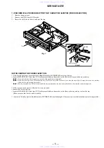
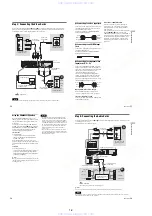
Hookups and Settings
Hooking Up the Recorder
Follow steps 1 to 7 to hook up and adjust the
settings of the recorder.
Notes
• Plug cords securely to prevent unwanted noise.
• Refer to the instructions supplied with the components
to be connected.
• You cannot connect this recorder to a TV that does not
have a video input jack.
• Be sure to disconnect the power cord of each
component before connecting.
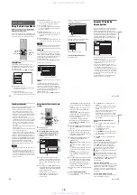
Step 1: Unpacking
Check that you have the following items:
• Audio/video cord (pinplug
u
3
y
pinplug
u
3)
(1)
• Power cord (1)
• Antenna cable (1)
• Remote commander (remote) (1)
• Set top box controller (1)
• Size AA (R6) batteries (2)
Step 2: Connecting the
Antenna Cable and Set Top
Box Controller
Select one of the following antenna hookups. Do
not connect the power cord until you reach “Step
5: Connecting the Power Cord” (page 21).
Using the cable box/satellite
receiver control function
The cable box/satellite receiver control function
can be used with hookup A or B. It allows the
recorder to control a cable box or satellite receiver
via the supplied set top box controller. The
recorder controls channels on the cable box or
satellite receiver for timer recording. You can also
use the recorder’s remote control to change
channels on the cable box/satellite receiver
whenever the cable box/satellite receiver is turned
on, even if the recorder is turned off.
To use the cable box/satellite receiver control
function, you need to connect the set top box
controller and set the code number and output
channel (page 24). After setting up the cable box/
satellite receiver control, check that the recorder
can correctly control the cable box or satellite
receiver (page 28).
Note to CATV system installer (in USA)
This reminder is provided to call the CATV
system installer’s attention to Article 820- 40 of
the NEC that provides guidelines for proper
grounding and, in particular, specifies that the
cable ground shall be connected to the grounding
system of the building, as close to the point of
cable entry as practical.
Notes
• If your antenna is a flat cable (300-ohm twin lead
cable), use an external antenna connector (not
supplied) to connect the antenna to the recorder.
• If you have separate cables for VHF and UHF
antennas, use a UHF/VHF band mixer (not supplied) to
connect the antenna to the recorder.
• If you have made hookup A or B and want to use the
TV Guide On Screen system, the cable box must be
turned on, the set top box controller must be connected,
and “Set Top Box Control” in Settings Setup must be
set to “On” (page 86) to download the TV Guide On
Screen data.
• If you are using the TV Guide On Screen system and
the recorder is receiving TV Guide On Screen data, you
may not be able to use the remote control to change
channels on the cable box when the recorder is off.
Wait until the recorder has finished receiving TV
Guide On Screen data.
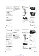
If you have
Hookup
Cable box or satellite receiver with a
video/audio output
A (page 13)
Cable box with an antenna output
only
B (page 14)
Cable without cable box, or antenna
only (no cable TV)
C (page 15)
13
H
ook
up
s and
Se
tti
n
gs
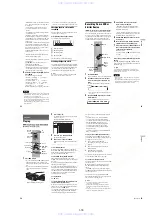
A: Cable box or satellite receiver with a video/audio output
With this hookup, you can record any channel on the cable box or satellite receiver. Be sure that the
satellite receiver or cable box is turned on.
To watch cable or satellite programs, you need to match the channel on the recorder (L1 or L3) to the
input jack connected to the cable box or satellite receiver (LINE IN 1 or 3). Note that satellite receiver
programs do not appear in the TV Guide On Screen system.
z
Hints
• If your cable box or satellite receiver has an S-video jack or component output jacks, you can use an S-video cord (not
supplied) or component video cord (not supplied) instead of the audio/video cord. When you connect using a
component video cord, connect the audio cords to the LINE IN jacks.
• If you connect an S-video cord to the LINE IN 1 jack or a component video cord, set “Line1 Input” in Video Setup to
“S Video” or “Component” (page 89). If you connect an S-video cord to the LINE IN 3 jack, set “Line3 Input” in
Video Setup to “S Video” (page 89).
VHF/UHF
IN
COMPONENT VIDEO IN
LINE IN
DIGITAL OUT
VIDEO
S VIDEO
COAXIAL
OPTICAL
PCM/DTS/DOLBY DIGITAL
AUDIO
R
L
1
3
LINE OUT
COMPONENT
VIDEO OUT
VIDEO
S VIDEO
AUDIO
R
L
1
2
Y
PB
PR
Y
PB
PR
~
AC IN
OUT
SET TOP BOX
CONTROL
CONTROL S IN
G-LINK
ANT IN
R
L
S VIDEO
AUDIO
OUT
VIDEO
OUT
COMPONENT
VIDEO OUT
TO TV
COMPONENT VIDEO IN
LINE IN
VIDEO
S VIDEO
AUDIO
R
L
1
3
Y
P
B
P
R
SET TOP BOX
CONTROL
Set top box
controller
(page 12)
to LINE IN
1 or 3
DVD recorder
Audio/video
cord (supplied)
: Signal flow
Place the set top box controller
near the remote sensor on the
cable box/satellite receiver.
Cable box/
satellite receiver
Antenna cable
(supplied)
to antenna input
S-video cord (not
supplied)
to SET TOP BOX
CONTROL
Wall
TV
Component video cord
(not supplied)
Note
Do not connect a hi-
definition tuner using the
component video cords. This
recorder only accepts
standard definition interlace
signals.
to
COMPONENT
VIDEO IN
,
continued
14
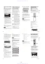
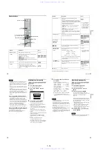
B: Cable box with an antenna output only
With this hookup, you can record any channel on the satellite receiver or cable box. Be sure that the
satellite receiver or cable box is turned on.
To watch cable programs, you need to match the channel on the recorder (2ch, 3ch, or 4ch) to the antenna
output channel on the cable box (2ch, 3ch, or 4ch).
COMPONENT VIDEO IN
LINE IN
DIGITAL OUT
VIDEO
S VIDEO
COAXIAL
OPTICAL
PCM/DTS/DOLBY DIGITAL
AUDIO
R
L
1
3
LINE OUT
COMPONENT
VIDEO OUT
VIDEO
S VIDEO
AUDIO
R
L
1
2
Y
PB
PR
Y
PB
PR
~
AC IN
SET TOP BOX
CONTROL
CONTROL S IN
ANT IN
TO TV
SET TOP BOX
CONTROL
Wall
DVD recorder
TV
to SET TOP
BOX
CONTROL
Set top box
controller
(supplied)
Cable box
Place the set top box controller
near the remote sensor on the
cable box/satellite receiver.
15
H
ook
up
s and
Se
tti
n
gs
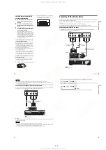
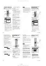
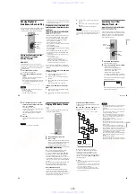
C: Cable without cable box, or antenna only (no cable TV)
Use this hookup if you watch cable channels without a cable box. Also use this hookup if you are using
a VHF/UHF antenna or separate VHF and UHF antennas.
With this hookup, you can record any channel by selecting the channel on the recorder.
VHF/UHF
IN
COMPONENT VIDEO IN
LINE IN
DIGITAL OUT
VIDEO
S VIDEO
COAXIAL
OPTICAL
PCM/DTS/DOLBY DIGITAL
AUDIO
R
L
1
3
LINE OUT
COMPONENT
VIDEO OUT
VIDEO
S VIDEO
AUDIO
R
L
1
2
Y
PB
PR
Y
PB
PR
~
AC IN
OUT
SET TOP BOX
CONTROL
CONTROL S IN
G-LINK
VHF/UHF
IN
OUT
DVD recorder
TV
to antenna input
to VHF/UHF IN
to VHF/UHF OUT
Antenna cable (supplied)
: Signal flow
Wall
www. xiaoyu163. com
QQ 376315150
9
9
2
8
9
4
2
9
8
TEL 13942296513
9
9
2
8
9
4
2
9
8
0
5
1
5
1
3
6
7
3
Q
Q
TEL 13942296513 QQ 376315150 892498299
TEL 13942296513 QQ 376315150 892498299


