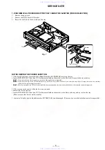


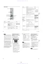


1-4
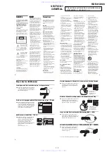
16
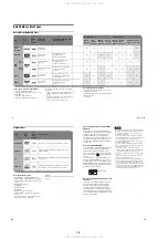
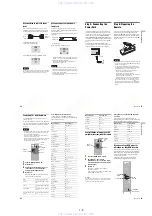
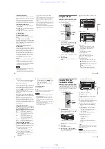
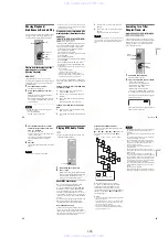
Step 3: Connecting the Video Cords
Select one of the following patterns
A
through
C
, according to the input jack on your TV monitor,
projector, or AV amplifier (receiver). This will enable you to view pictures. Audio connections are
explained in “Step 4: Connecting the Audio Cords” (page 19).
Note
Do not connect more than one type of video cord between the recorder and your TV at the same time.
VHF/UHF
IN
COMPONENT VIDEO IN
LINE IN
DIGITAL OUT
VIDEO
S VIDEO
COAXIAL
OPTICAL
PCM/DTS/DOLBY DIGITAL
AUDIO
R
L
1
3
LINE OUT
COMPONENT
VIDEO OUT
VIDEO
S VIDEO
AUDIO
R
L
1
2
Y
PB
PR
Y
PB
PR
~
AC IN
OUT
SET TOP BOX
CONTROL
CONTROL S IN
G-LINK
VIDEO
AUDIO
INPUT
L
R
CONTROL S
INPUT
S VIDEO
P
R
P
B
Y
COMPONENT
VIDEO IN
B
A
C
Audio/video
cord (supplied)
Component video
cord (not supplied)
(yellow)
TV, projector, or AV
amplifier (receiver)
TV, projector, or AV
amplifier (receiver)
(green)
S-video cord
(not supplied)
TV, projector, or AV
amplifier (receiver)
(red)
(blue)
(green)
(blue)
(red)
: Signal flow
to COMPONENT
VIDEO OUT
to LINE OUT (VIDEO) 1 or 2
to LINE OUT (S VIDEO) 1 or 2
DVD recorder
to CONTROL S IN
TV or other equipment with a
CONTROL S jack
17
H
ook
up
s and
Se
tti
n
gs
A
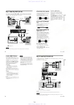
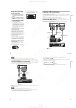
Connecting to a video input jack
Connect the yellow plug of the audio/video cord
(supplied) to the yellow (video) jack. You will
enjoy standard quality images.
Note that you cannot use the PROGRESSIVE
button with this connection.
B
Connecting to an S VIDEO input
jack
Connect an S-video cord (not supplied). You will
enjoy high quality images.
Note that you cannot use the PROGRESSIVE
button with this connection.
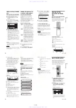
C
Connecting to component video
input jacks (Y, P
B
, P
R
)
Connect the COMPONENT VIDEO OUT jacks
using a component video cord (not supplied) or
three video cords (not supplied) of the same kind
and length. You will enjoy accurate color
reproduction and high quality images.
If your TV accepts progressive 480p format
signals, you must use this connection and then
press PROGRESSIVE on the remote to send
progressive video signals. For details, see “Using
the PROGRESSIVE button” (page 18).
When playing “wide screen” images
Some recorded images may not fit your TV
screen. To change the aspect ratio, see page 87.
If you are connecting to a VCR
Connect your VCR to the LINE IN (VIDEO) jack
on the recorder (page 29).
If your TV has a CONTROL S jack
You can control the recorder by pointing the
remote at your TV. This feature is convenient
when you place the recorder and the TV away
from each other.
After connecting the recorder to other equipment
in pattern
A
,
B
, or
C
above, connect the
CONTROL S IN jack to your TV’s CONTROL S
(OUT) jack using a control S cord (not supplied).
See the instructions supplied with the TV to be
connected. Note that your TV’s input will not
automatically switch to this recorder when you
play a disc.
Yellow
White (L)
Red (R)
Yellow
White (L)
Red (R)
Green
Blue
Red
Green
Blue
Red
,
continued
18
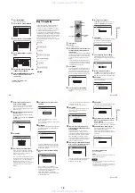
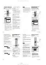
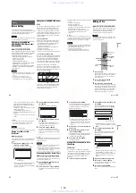
Using the PROGRESSIVE button
By using the PROGRESSIVE button on the
remote, you can select the signal format in which
the recorder outputs video signals: Interlace or
Progressive.
Connect the recorder using the COMPONENT
VIDEO OUT jacks (pattern
C
above), and press
PROGRESSIVE repeatedly. “PROGRESSIVE”
appears in the front panel display when the
recorder outputs progressive signals.
◆
Progressive
Select this when:
– your TV accepts progressive signals, and,
– the TV is connected to the COMPONENT
VIDEO OUT jacks.
COMPONENT VIDEO OUT jacks (LINE OUT
(VIDEO) or S VIDEO).
Notes
• Consumers should note that not all high definition
television sets are fully compatible with this product
and may cause artifacts to be displayed in the picture.
In the case of 480 progressive scan picture problems, it
is recommended that the user switch the connection to
the ‘standard definition’ output. If there are questions
regarding our TV set compatibility with this model
480p DVD recorder, please contact our customer
service center.
• TV Guide On Screen does not appear if you connect
your TV using the video or S-video jacks and press the
PROGRESSIVE button on the remote, even if your TV
accepts progressive signals.
19
H
ook
up
s and
Se
tti
n
gs
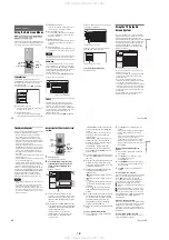
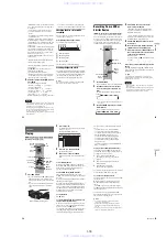
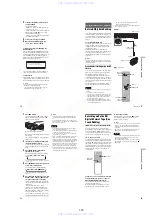
Step 4: Connecting the Audio Cords
Select one of the following patterns
A
or
B
, according to the input jack on your TV monitor, projector,
or AV amplifier (receiver).
This will enable you to listen to sound.
z
Hint
For correct speaker location, see the operating instructions supplied with the connected components.
Note
Do not connect your TV’s audio output jacks to the LINE IN (AUDIO L/R) jacks at the same time. This will cause
unwanted noise to come from your TV’s speakers.
VHF/UHF
IN
COMPONENT VIDEO IN
LINE IN
DIGITAL OUT
VIDEO
S VIDEO
COAXIAL
OPTICAL
PCM/DTS/DOLBY DIGITAL
AUDIO
R
L
1
3
LINE OUT
COMPONENT
VIDEO OUT
VIDEO
S VIDEO
AUDIO
R
L
1
2
Y
PB
PR
Y
PB
PR
~
AC IN
OUT
SET TOP BOX
CONTROL
CONTROL S IN
G-LINK
VIDEO
AUDIO
INPUT
L
R
LINE OUT
VIDEO
S VIDEO
AUDIO
R
L
1
2
B
A
DIGITAL OUT
COAXIAL
OPTICAL
PCM/DTS/DOLBY DIGITAL
AV amplifier (receiver)
with a decoder
(red)
TV, projector, or AV
amplifier (receiver)
Audio/video
cord (supplied)
: Signal flow
Coaxial digital cord
(not supplied)
to DIGITAL OUT (COAXIAL or
OPTICAL)
to LINE OUT (R-AUDIO-L) 1 or 2
Optical digital cord (not supplied)
Rear (L)
DVD recorder
(white)
(yellow)
*
(yellow)
(white)
(red)
[Speakers]
Front (L)
[Speakers]
to coaxial
digital input
Rear (R)
Front (R)
Subwoofer
or
Center
* The yellow plug is used for video signals (page 17).
to optical
digital input
,
continued
www. xiaoyu163. com
QQ 376315150
9
9
2
8
9
4
2
9
8
TEL 13942296513
9
9
2
8
9
4
2
9
8
0
5
1
5
1
3
6
7
3
Q
Q
TEL 13942296513 QQ 376315150 892498299
TEL 13942296513 QQ 376315150 892498299


