background image

2-10 (E)

NSS-S2

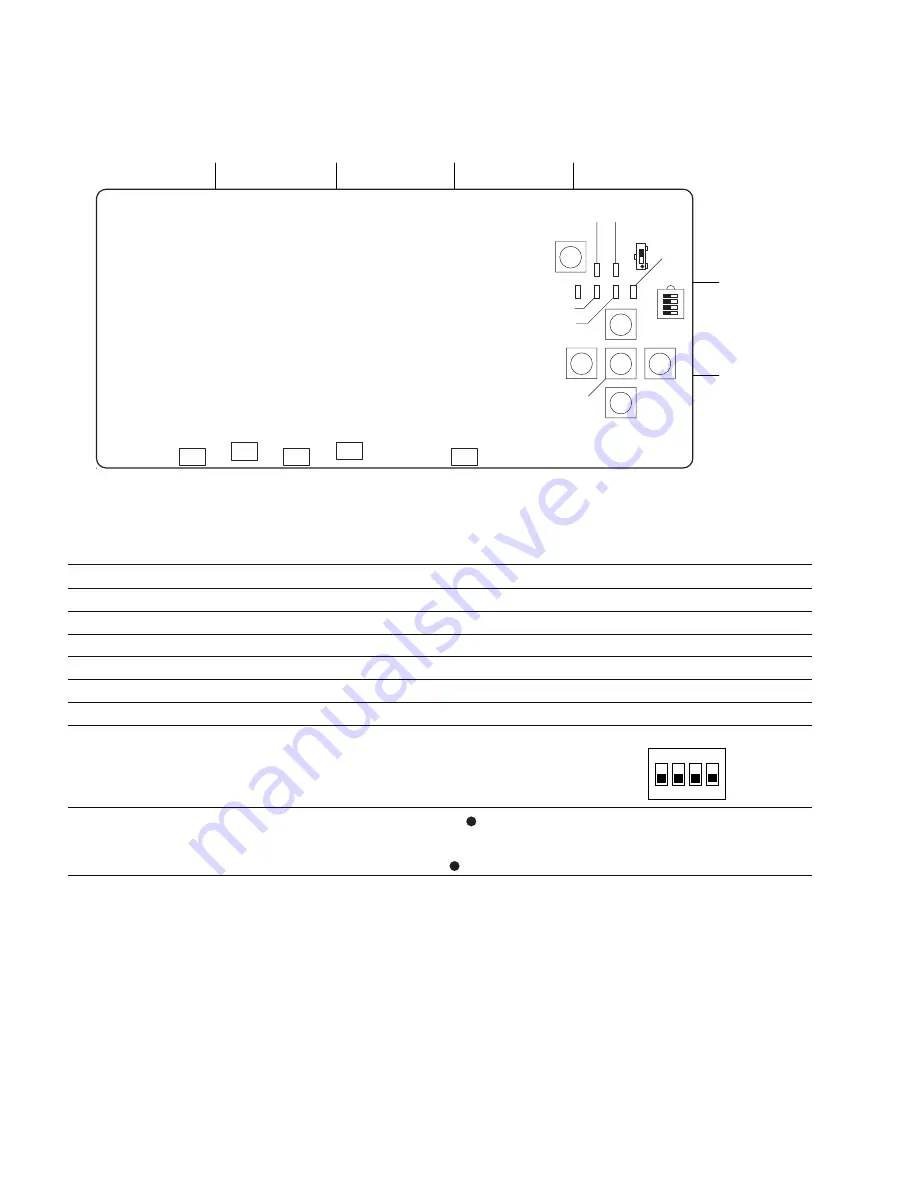
2-2-3. DP-405 Board

Switches

Ref. No. Address

Name

Function

Factory setting

S101

(E-1)

Reset switch

Initializes the DP-405 board.

_

S102

(E-2)

LEFT_KEY

Control panel left-arrow key

_

S103

(E-2)

UP_KEY

Control panel up-arrow key

_

S104

(E-2)

ENTER_KEY

Control panel ENTER key

_

S105

(E-3)

DOWN_KEY

Control panel down-arrow key

_

S106

(E-2)

RIGHT_KEY

Control panel right-arrow key

_

S107

(E-2)

Mode setting switch

S107-1 ON : CPU CLOCK (DP) 16 MHz

All OFF

OFF : CPU CLOCK (DP) 20 MHz

S107-2 ON : Control panel ON

OFF : Control panel OFF

S107-3, 4 :

Not used

S108

(E-1)

RS-232C#1

“2” side (the side without     ): For hard-debug

“2” side

selection switch

(do not change except for
factory setting)

“3” side (the side with     ): EXP

ON

1

2

3 4

(Side A/component side)

A

B

C

D

S101

S108

S107

S102

S103

S104

S105

S106

D112

D111

D108

D109

D110

E

1

2

3

D113

D114

D104

D105
D106

D107

Summary of Contents for NSS-S2

Page 1: ...MEDIA STORAGE UNIT NSS S2 INSTALLATION MANUAL 1st Edition Revised 1 Serial No 10001 and Higher ...

Page 2: ...ctrique d incendie ou de blessure n effectuer que les réparations indiquées dans le mode d emploi à moins d être qualifié pour en effectuer d autres Pour toute réparation faire appel à une personne compétente uniquement WARNING This unit has no AC power switch When installing the unit incorporate a readily accessible disconnect device in the fixed wiring or connect the power cord to a socket outle...

Page 3: ...alled in a rack please make sure that the rack does not achieve hazardous condition due to uneven mechanical loading 5 Install the equipment while taking the operating temperature of the equipment into consideration For the operating temperature of the equipment refer to the specifications of the Operation Manual 6 When performing the installation keep the following space away from walls in order ...

Page 4: ...her Mount in a rack to avoid the risk of the unit sliding and causing injury Ground the unit safely Failure to ground the unit may cause electric shock Handling the unit by holding the designated positions When handling the unit be sure to hold the following positions Otherwise the unit may break and fall causing injury Rack angle Bottom case Especially do not hold the front panel or the handle of...

Page 5: ...ling the HDD Unit 1 8 E 1 8 Signal Input and Output 1 9 E 1 9 Connecting Connectors and Cables 1 9 E 1 10 Connection 1 10 E 1 11 Checks after Connection 1 11 E 1 12 Menu Settings 1 13 E 1 12 1 Displaying of Menus 1 13 E 1 12 2 Setting of Device Name 1 14 E 1 12 3 Setting of Network 1 15 E 1 12 4 Executing of Logical Formatting 1 16 E 1 13 SNMP 1 17 E 1 13 1 Setting of Community Name 1 17 E 1 13 2 ...

Page 6: ......

Page 7: ...acement service overview maintenance functions replacement of the parts and boards circuit descriptions and block diagram etc If this manual is required please contact your local Sony Sales Office Service Center Part number 9 968 191 XX Contents The following is a summary of all the section for understanding the contents of this manual Section 1 Installation Explains the operating conditions insta...

Page 8: ......

Page 9: ...power is turned on or within about 30 seconds after turning off the power Be extremely careful when removing and or installing the HDD unit or power supply unit while the unit is in live state Cautions about rack mounting the unit Mount in the rack after removing all built in HDD from the unit Never give shock to all the rack mounted unit which has a HDD Caution about static electricity Keep stati...

Page 10: ...er strong lights Dusty areas or areas where is subjected to vibration Areas with strong electric or magnetic fields Areas near heat sources Areas where is subjected to electrical noise Areas where is subjected to static electricity noise Unstable and unbalanced areas 3 To prevent the internal temperature rise pay attention to circulation of air in the place where this unit is installed The rear si...

Page 11: ...this unit should be 50 cm away from the walls for maintenance and replacement of the power supply unit If the power is turned on with the cabinet removed the air cooling effect of the fan is greatly reduced which can result in damaging the PU 124 board and HDD or its data Avoid the operation when the cabinet is removed MEDIA STORAGE UNIT NSS S2 POWER SYSTEM BUSY 440 440 402 465 35 4 263 5 231 115 ...

Page 12: ...turn off the power in case a fault should occur 2 1 AC inlet 2 1 AC inlet AC inlet 2 1 1 4 2 Recommended Power Cord Recommended parts For customers in the U S A and Canada 1 Power cord 125 V 10 A 2 4 m 1 551 812 31 2 Plug holder Brown 3 613 640 01 For customers in the United Kingdom 1 Power cord 250 V 10 A 2 4 m 1 551 631 61 2 Plug holder Brown 3 613 640 01 For customers in European countries exce...

Page 13: ...e management data stored in the unit is erased and the unit returns to the factory default state Be sure to set the switch for the backup battery to ON 1 Remove the two screws and pull out the PU 124 board assembly in the direction of the arrow while holding the handle S2002 BATTERY ON BATTERY OFF PU 124 board assembly 2 Set S2002 E 1 to ON 3 Install the PU 124 board assembly by reversing step 1 ...

Page 14: ...t in the rack after removing the HDD from the unit Componets of RMM 10 Rack brackets 2 pcs Rack mounting adaptor right 1 pc Including two screws B4 x 6 7 682 560 09 Rack mounting adaptor left 1 pc Including two screws B4 x 6 7 682 560 09 Rack bracket fixing screws 6 pcs B4 x 6 7 682 560 09 Adaptor fixing screws B4 x 10 7 682 562 09 6 pcs Required other parts To mount the unit in the rack the follo...

Page 15: ...re is case of left side 6 Fasten the length adjustment screws which are loos ened in step 4 B4 x 6 Adaptor Portion of the rail Unit mm 31 75 31 75 B4 x 10 B4 x 10 3U 7 Align the crook of the each rack bracket on the side panels of the unit with the rail then slide the unit backward n Each rack bracket covers the rails as shown in the figure below 8 Fix the unit to the rack with the specified screw...

Page 16: ... with drop safe and remove the front panel 2 Open the control panel Board facing up Cushion 3 After the lever starts rotating insert the HDD unit into the slot carefully and push the lever slowly in the direction of the arrow A to attach it n Insert the HDD unit so that the board on the HDD unit faces to the left when viewed from the front 4 Stick the HDD No label for the slot on the front Screws ...

Page 17: ... Signal 1 TX 2 RX 1 9 Connecting Connectors and Cables When connecting cables to various connectors on the rear panel at the time of installing or servicing connect the following connectors cable or their equivalents NSS S2 Matching Connector Cable Panel Indication Connector Connector Cable Sony Part No 100BASE TX Modular jack RJ45 _ UTP Unshielded twisted pair cable FIBRE CHANNEL LC connector Opt...

Page 18: ... Ethernet 1 Ethernet 1 Ethernet 2 Ethernet 2 REF VIDEO IN TC IN 9pin Controller Fibre Channel Switch File Manager PC Transfer Manager PC SDI OUT SDI IN TC IN REMOTE REMOTE 100BASE TX LOCAL 1 100BASE TX LOCAL 1 100BASE TX LOCAL 1 FC 2 FC 1 100BASE TX 1 100BASE TX LOCAL 1 Fibre Channel 1 Fibre Channel 2 TC IN REF VIDEO IN SDI OUT REMOTE 9pin Controller NSS V2 NSS V2 NSS S2 NSS S2 FC 1 100BASE TX 1 E...

Page 19: ...he SYSTEM Green Blinks during the unit initialization lamp on the front panel Self diagnostic ends normally and the unit is running normally Amber An abnormality occurred in the unit blinking recording and playing are possible Or the link of FIBRE CHANNEL is not established Red blinking Fatal abnormality occurred in the unit recording and playing are not possible 3 Check the lighting color of the ...

Page 20: ...color of the HDD indicator Green The corresponding HDD is running normally lamp on top of the slot Lights on Green blinking during the recording and playing the corresponding HDD Amber Initializing the corresponding HDD is in Lights on progress or warning occurs Red An abnormality ocurred in the corresponding Lights on HDD 2 Or HDD is not installed 1 When replacing the power unit refer to the Main...

Page 21: ...NTER key to open the MAIN menu screen Displaying of CONFIGURATION menu 1 Remove the front panel and turn on the power of the unit Refer to Section 1 7 The MAIN menu screen is displayed 2 When the MAIN menu screen is displayed display the UNIT CONFIG using UP or DOWN key 3 Press ENTER key to open the CONFIGURATION menu screen Returning to MAIN menu screen 1 On the CONFIGURATION menu screen display ...

Page 22: ...name m Enter a device name within 16 characters A to Z and underscore _ are available for a device name 1 Select a desired character using UP or DOWN key 2 Press RIGHT or LEFT key to move the cursor position 5 After selecting the last character press ENTER key 6 The check screen is displayed Set the cursor to OK using RIGHT or LEFT key and press ENTER key 7 The device name is set and the display r...

Page 23: ...r selecting the last number press ENTER key 5 The check screen is displayed Set the cursor to OK using RIGHT or LEFT key and press ENTER key The IP address is set and the display returns to the CONFIGURATION menu screen 6 Display the NETMASK using UP or DOWN key 7 Set a subnet mask in the same procedure as steps 3 and 4 8 Display the DEFAULT GATEWAY using UP or DOWN key 9 Set a gateway in the same...

Page 24: ...the FORMAT using UP or DOWN key 3 Press ENTER key 4 Press ENTER key without changing the screen 5 The check screen is displayed Set the cursor to OK using RIGHT or LEFT key and press ENTER key 6 Press ENTER key to return to the CONFIGURATION menu screen FORMAT EXECUTE ENT LUN D P S 0 10 4 1 EXECUTE SUCCESS ENT EXECUTE OK ABORT ...

Page 25: ...etting is 0 0 0 0 Set up using the control panel menu n For each MIB structure get information and description of trap sent from NSS S2 to SNMP Manager refer to the maintenance manual of NSS S2 1 13 1 Setting of Community Name 1 Display the CONFIGURATION menu screen Refer to Section 1 12 1 2 Display the SNMP COMMUNITY using UP or DOWN key 3 Press ENTER key to enter a new community name 4 Repeat th...

Page 26: ...check screen is displayed Set the cursor to OK using RIGHT or LEFT key and press ENTER key 1 14 Setting of FAN MODE A operation mode of fan installed in FAN UNIT is changed OFF Normal mode factory setting ON Silent mode 1 Display the CONFIGURATION menu screen Refer to Section 1 12 1 2 Display the FAN SILENT using UP or DOWN key 3 Press ENTER key When the cursor appeared change to ON from OFF using...

Page 27: ... on the filter impedes the flow of air the inside may heat up and troubles may occur Clean the filter periodically Cleaning 1 Turn off the main power of the NSS S2 2 Remove the front panel Refer to Section 1 7 3 Remove the filter in the direction of the arrow 4 Remove the dust from the filter using a vacuum 5 Attach the filter in reverse order of the disassembly procedure ...

Page 28: ...40 D8025 D8026 D8027 D8028 D8029 D8030 D8031 D8032 D8033 D8034 D8035 D8036 D8013 D8014 D8015 D8016 D8017 D8018 D8019 D8020 D8021 D8022 D8023 D8024 D8001 D8002 D8003 D8004 D8005 D8006 D8007 D8008 D8009 D8010 D8011 D8012 D8537 D8538 D8539 D8540 D8525 D8526 D8527 D8528 D8529 D8530 D8531 D8532 D8533 D8534 D8535 D8536 D8513 D8514 D8515 D8516 D8517 D8518 D8519 D8520 D8521 D8522 D8523 D8524 D8501 D8502 D...

Page 29: ...or factory All OFF setting S2502 1 to 8 all OFF For normal use S4001 G 9 IFPLD setting switch S4001 1 ON JTAG CPU CPU FLASH ACSESS S4001 2 ON DW MODE S4001 3 ON M MODE S4001 4 ON MODE S4001 5 Not used S4001 6 Not used S4001 7 ON XWP_ACC S4001 8 ON IFPLD1_SEL S4002 F 9 ISP selection switch S4002 1 ON ALTERA LOOP 1 1 enable S4002 2 ON ALTERA LOOP 2 2 enable S4002 3 ON LATTICE LOOP 3 enable S4002 4 O...

Page 30: ...figuration is complete D2010 F 1 Red HOT_PLUG_ERROR0 Lights when an error occurs on the channel 0 Lights off side of HOT PLUG LSI D2304 E 3 Red 3 3 V 1 2 V_SAS_ Lights when an error occurs in the DD converter Lights off CORE_DD CON_ERROR LSI that generates 3 3 V 1 2 V D3201 A 7 Blue ETHERNET_FAST0_ Lights when Fast Ethernet PHY establishes a link Lights off FULLDUPLEX in Full Duplex D3202 A 7 Blue...

Page 31: ...5 Green SAS1064_LSI2_ACTIVITY2 D7503 G 5 Green SAS1064_LSI2_ACTIVITY1 D7504 G 5 Green SAS1064_LSI2_ACTIVITY0 D7505 G 5 Green SAS1064_LSI2_LIFEBEET Blinks when SAS1064 LSI2 is ready to start Blinking operation D7506 G 4 Red SAS1064_LSI2_FOULT3 Lights off D7507 G 4 Red SAS1064_LSI2_FOULT2 D7508 G 4 Red SAS1064_LSI2_FOULT1 D7509 G 4 Red SAS1064_LSI2_FOULT0 D8001 H 3 Red SASX12_LSI1_FAULT11 Blinking D...

Page 32: ...2 H 3 Green SASX12_LSI1_STATUS4 Lights off D8033 H 3 Green SASX12_LSI1_STATUS3 Lights off D8034 H 3 Green SASX12_LSI1_STATUS2 Lights off D8035 J 3 Green SASX12_LSI1_STATUS1 Lights off D8036 J 3 Green SASX12_LSI1_STATUS0 Lights off D8037 H 3 Green SASX12_LSI1_GPIO3 For design purpose Lights off D8038 H 3 Green SASX12_LSI1_GPIO2 D8039 H 3 Green SASX12_LSI1_GPIO1 D8040 H 3 Green SASX12_LSI1_GPIO0 D85...

Page 33: ...SI2_STATUS11 Blinking D8526 G 3 Green SASX12_LSI2_STATUS10 Lights off D8527 G 3 Green SASX12_LSI2_STATUS9 Lights off D8528 G 3 Green SASX12_LSI2_STATUS8 Lights off D8529 G 3 Green SASX12_LSI2_STATUS7 Lights off D8530 G 3 Green SASX12_LSI2_STATUS6 Lights off D8531 G 3 Green SASX12_LSI2_STATUS5 Lights off D8532 G 3 Green SASX12_LSI2_STATUS4 Lights off D8533 G 3 Green SASX12_LSI2_STATUS3 Lights off D...

Page 34: ... 0 to the MPU board side S701 2 to 4 Not used S701 5 ON PCI X Clock 33 MHz OFF PCI X Clock 66 MHz S701 6 ON RIO ID OFF RIO ID S701 7 ON PCI X Wide 32 bit OFF PCI X Wide 62 bit S701 8 ON PCI Mode OFF PCI X Mode S1 B 5 Reset switch Initializes the MPU 136 board _ ON 1 2 3 4 5 6 7 8 S701 A B C D E F G H J K 1 2 3 4 5 6 7 8 9 S1 D701 D702 D703 D704 D705 D706 D707 D708 1 D601 D604 D603 D602 Side A comp...

Page 35: ...ry Use Lights off D602 C 1 Green _ Lights off D603 C 1 Green _ Lights off D604 C 1 Green _ Lights on D701 G 1 Green _ Factory Use Lights off D702 G 1 Green _ Lights off D703 G 1 Green _ Lights off D704 G 1 Green _ Lights off D705 G 1 Green _ Lights off D706 G 1 Green _ Lights off D707 G 1 Green _ Lights on D708 G 1 Green _ Lights on ...

Page 36: ...wn arrow key _ S106 E 2 RIGHT_KEY Control panel right arrow key _ S107 E 2 Mode setting switch S107 1 ON CPU CLOCK DP 16 MHz All OFF OFF CPU CLOCK DP 20 MHz S107 2 ON Control panel ON OFF Control panel OFF S107 3 4 Not used S108 E 1 RS 232C 1 2 side the side without For hard debug 2 side selection switch do not change except for factory setting 3 side the side with EXP ON 1 2 3 4 Side A component ...

Page 37: ...ed D110 A 3 Green POWER Indicates the state of the power supply unit Lights on Green Amber Normal Lights in green Red Failure of one power supply Blinks in amber Failure of two power supplies Blinks in red D111 C 3 Green RESERVE2 For debug Lights off Amber Red D112 D 3 Green BUSY Accessing HDD Lights in green Lights off Lights in green when accesing the HDD is in progress D113 E 1 Blue 5 V Lights ...

Page 38: ......

Page 39: ...de Sony Corporation Sony Corporation interdit formellement la copie de quelque partie que ce soit de ce manuel ou son emploi pour tout autre but que des opérations ou entretiens de l équipement à moins d une permission écrite de Sony Corporation Das in dieser Anleitung enthaltene Material besteht aus Informationen die Eigentum der Sony Corporation sind Die Sony Corporation untersagt ausdrücklich d...

Page 40: ...Printed in Japan Sony Corporation 2006 12 16 2005 NSS S2 SY J E 3 903 855 02 ...

Reviews: