1-32
MVS-8000X/7000X
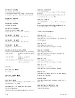
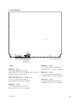
D401 (B-8) : CC1_UNLOCK
Indicates lock/unlock of the clock conditioner for OUT,
MSD, CCR.
If this LED lit, the clock conditioner can possibly be
unlocked.
D402 (L-5) : CC2_UNLOCK
Indicates lock/unlock of the clock conditioner for FC OUT
FPGA.
If this LED lit, the clock conditioner can possibly be
unlocked.
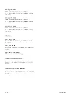
D1101 (C-1) : STATUS
For future expansion.
D1102 (B-1) : POWER
Power supply status indication.
Lights in green when all power supply on the board are
normally. If the power supply has abnormality, turns off.
D1103 (F-1) : PLL ULK
Indicates lock/unlock of the PLL (Phase Locked Loop) in
the FPGA.
If this LED lit, the PLL can possibly be unlocked.
D1104 (B-1) : BECON
For future expansion.
D1201, D1202 (F-1) : CNF ERR
Indicates the con
fi
guration error of the FPGA.
If this LED lit, any FPGA can possibly be working incor-
rectly.
D2701 to D2708 (E-1, F-1) :
+
1.0V-AVCC1 to 8
+
1.0 V analog power supply status indication.
Lights when the
+
1.0 V power is supplied.
D2709 to D2716 (E-1, F-1) :
+
1.2V-APLL1 to 8
+
1.2 V analog power supply status indication.
Lights when the
+
1.2 V power is supplied.
D2717 to D2719 (F-1) :
+
1.2V-AVTTR, C, L
+
1.2 V analog power supply status indication.
Lights when the
+
1.2 V power is supplied.
D2720 (D-1) : ALL_MGT_PWR
All analog power supplies (
+
1.0 V to
+
1.2V) status indica-
tion.
Lights when the all power (
+
1.0 V-AVCC1 to 8,
+
1.2
V-APLL1 to 8,
+
1.2 V-AVTTR, C, L) are supplied.
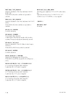
D3101 to D3108 (K1) : IMP1 DISP
CCR1 status indication.
D3501 to D3108 (L1) : IMP2 DISP
CCR2 status indication.
< Switch >
S501 (M-1) : RST
For design.
Summary of Contents for MVS-8000X System
Page 4: ......
Page 54: ......
Page 58: ...Sony Corporation MVS 7000X SY MVS 8000X SY E 4 189 509 03 Printed in Japan 2011 5 08 2010 ...


