1-28
MVS-8000X/7000X
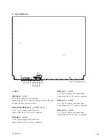
3. MIX-53
Board
12
13
11
10
9
8
7
6
5
4
3
2
1
A
B
C
D
E
F
G
H
J
K
L
M
N
P
R
D719
D721
D718
D414
D416
D418
D415
D417
D419
D310
D304
D305
D31
1
D308
D301
D302
D303
D720
D1402
D203
D309
D307
D306
D501
D701
D1401
D1413
D1412
D141
1
D1410
D1409
D1406
D1405
D1404
D1403
D1408
D1407
D1001 D1002
S501
S901
S902
D705
D713
D708
D716
D702
D710
D706
D704
D714
D712
D717
D709
D707
D703
D715
D71
1
CPU-DP
Module
6
5
4
3
2
1
A
B
C
D
E
F
G
H
D1
D3
D5
D2
D4
D16
D17
D1
1
D10
D9
D8
D7
D15 D14 D13 D12
D6
SW2
Side A (Component Side)
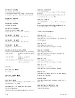
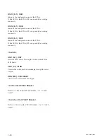
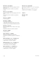
< LED >
D719 (B-1) : POWER
Power supply status indication.
Lights in green when all power supply on the board are
normally.
D203 (C-1) :
+
12 V
+
12 V power supply status indication.
Lights when the
+
12 V power is supplied. If this LED does
not light, the fuse may have blown.
D301, D302, D303 (F-1) :
+
1.0 V-1, -2, -3
+
1.0 V power supply status indication.
Lights when the
+
1.0 V power is supplied.
D304, D305, D311, D308 (E-1) :
+
1.1 V-1, -2, -3, -4
+
1.1 V power supply status indication.
Lights when the
+
1.1 V power is supplied.
D306 (D-1) :
+
1.8 V
+
1.8 V power supply status indication.
Lights when the
+
1.8 V power is supplied.
D307 (C-1) :
+
2.5 V
+
2.5 V power supply status indication.
Lights when the
+
2.5 V power is supplied.
Summary of Contents for MVS-8000X System
Page 4: ......
Page 54: ......
Page 58: ...Sony Corporation MVS 7000X SY MVS 8000X SY E 4 189 509 03 Printed in Japan 2011 5 08 2010 ...


