background image

1-19

MVS-8000X/7000X

1-8.  Checks on Completion of Installation

1-8-1.  Description of On-board Switches and LEDs

n

The number shown in the parentheses ( ) indicated the address on the circuit board.

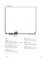
1. CA-82 

board

1

B

A

C

D

E

F

G

H

J

L

M

N

P

R

K

2

3

4

5

6

7

8

9

10

11

12

CPU-DP
Module

D801

S901 S904

S401

S902 S903

S402

D202

D310

D204

D205

D306

D305

D206

D308

D203

D307

D201

D805

D804

D803

D802

D917

D918

D919

D920

D1201

D1308
D1307
D1306
D1305
D1304
D1302
D1301

D2403

D2402

D2401

D2406

D2405

D2404

D1

101

D1

102

D2503

D2502

D2501

D2506

D2505

D2504

D2204
D2203
D2202
D2201

D2304
D2303
D2302
D2301

D2701

D2702

D2703

D2802

D2901

D2902

D2903

D3002

D2704

D2705

D2706

D2801

D2904

D2905

D2906

D3001

D2707

D2708

D2709

D2803

D2907

D2908

D2909

D3003

D3604
D3603
D3602
D3601

D3605

D3606

D3607

D3701

D3702

D3703

D3704

D4101

D4102

D4103

S501

S2201

S2202

S2302

S2301

D403

D402

D401

Side A (Component Side)

D100

D101

D200

A

B

1

2

SG-272

S500

S300

D202
D201
D200

A

B

C

D

E

F

G

1

2

3

4

SIO-26

6

5

4

3

2

1

A

B

C

D

E

F

G

H

D1

D3

D5

D2

D4

D16

D17

D1

1

D10

D9

D8

D7

D15 D14 D13 D12

D6

SW2

< LED >

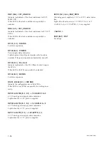
D201 (B-1) : 1.0 V

+

1.0 V power supply status indication.

Lights when the 

+

1.0 V power is supplied.

D202 (A-1) : 12 V

+

12 V power supply status indication.

Lights when the 

+

12 V power is supplied. If this LED does 

not light, the fuse may have blown.

Summary of Contents for MVS-8000X System

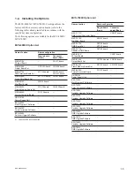
Page 1: ...7000X HK PSU05 MKS 7171X MKS 7471X MKS 8170X MKS 8440X BZS 7200X BZS 7510X BZS 7540X BZS 7561X BZS 8560X MKS 7210X MKS 8110X MKS 8180X MKS 8450X BZS 7420X BZS 7520X BZS 7541X BZS 8200X MKS 7470X MKS 8160X MKS 8210X BZS 7500X BZS 7530X BZS 7560X BZS 8420X INSTALLATION MANUAL 1st Edition Revised 2 ...

Page 2: ...sitzen AVERTISSEMENT Ce manual est destiné uniquement aux personnes compétentes en charge de l entretien Afin de réduire les risques de décharge électrique d incendie ou de blessure n effectuer que les réparations indiquées dans le mode d emploi à moins d être qualifié pour en effectuer d autres Pour toute réparation faire appel à une personne compétente uniquement MVS 8000X SY Serial No 10001 and...

Page 3: ...en mechanical loading 5 Install the equipment while taking the operating temperature of the equipment into consideration For the operating temperature of the equipment refer to the specifications of the Operation Manual 6 When performing the installation keep the follow ing space away from walls in order to obtain proper exhaust and radiation of heat Front Right and Left 10 cm 4 inches or more c F...

Page 4: ......

Page 5: ...4 2 Installing the Connector Board 1 8 1 4 3 Installing the HK PSU05 1 10 1 4 4 Installing the Software Options 1 10 1 5 Rack Mounting 1 11 1 5 1 MVS 8000X 1 11 1 5 2 MVS 7000X 1 13 1 6 Matching Connectors 1 15 1 6 1 MVS 8000X 1 15 1 6 2 MVS 7000X 1 16 1 7 Input Output Signals of Connectors 1 17 1 8 Checks on Completion of Installation 1 19 1 8 1 Description of On board Switches and LEDs 1 19 1 9 ...

Page 6: ... information that is required to connect the MVS 8000X MVS 7000X MVE 9000 MKS 8700 CCP 8000 to the MVS 8000 system and to start up the system If this manual is required please contact your local Sony Sales Office Service Cen ter Maintenance Manual Available on request This manual describes the detailed service information If this manual is required please contact your local Sony Sales Office Servi...

Page 7: ...Section 1 Installation 1 2 Power Supply 1 2 1 Power Specifications A switching regulator is used for the power supply of this unit The voltage within the range of 100 V to 240 V can be used without changing the supply voltage Power requirements AC 100 to 240 V 10 Power frequency 50 60 Hz Current consumption when all options are installed MVS 8000X 15 to 6 5 A MVS 7000X 15 to 6 5 A m As the inrush ...

Page 8: ...conforming to the proper ratings Volt age Ampere If you have questions on the use of the above Power Cord Appliance Connector Plug please contact your local Sony Sales Office Service Center c Never use an injured power cord Plugging the power cord in the AC inlet push as far as it will go For customers in the U S A and Canada 1 Power cord 125 V 10 A 2 4 m 1 551 812 31 AC inlet 1 For customers in t...

Page 9: ...1 3 MVS 8000X 7000X 1 3 Installation Space External dimensions 1 3 1 MVS 8000X 482 45 2 420 4 129 5 115 5 115 5 410 8 443 6 10U 17 5 440 497 10 7 26 Unit mm ...

Page 10: ...1 4 MVS 8000X 7000X 1 3 2 MVS 7000X 410 8 129 5 115 5 115 5 482 45 2 420 4 17 5 354 7 8U 26 Unit mm 497 440 7 10 ...

Page 11: ... Software _ _ BZS 8420X Color Correction Software _ _ BZS 8560X Switcher Upgrade Software _ _ 1 Currently M E4 is not supported MVS 7000X Option List Name of option Board configuration Plug in board Front Connector board Rear MKS 7171X DME Output Connector Board _ CNO 37 board MKS 7210X Mix Effect Board MIX 53 board _ MKS 7470X DME Board Set DVP 53 board XPT 32 board _ MKS 7471X Additional DME Boa...

Page 12: ...uction c Check to see that connectors of the plug in boards are securely inserted into the mother board MVS 8000X MB 1150 board MVS 7000X MB 1151 board without loose contact If any plug in board is inserted into the incorrect slot it causes a system error and the system will not work correctly After installing the plug in board the software must be installed Install the software same version as th...

Page 13: ...KS 8180X XPT 31A board 6 MKS 8210X 1 MIX 53 board 1 2 4 MKS 8440X MY 118 board 16 MKS 8450X FC 112 board 11 12 1 Installation order of MIX 53 board First board Slot no 8 standard Second board Slot no 7 standard Third board Slot no 4 option Fifth board Slot no 2 option Sixth board Slot no 1 option MVS 7000X Option List Name of option Name of board Slot on the front side MKS 7210X 1 MIX 53 board 5 6...

Page 14: ...lock button This figure shows MVS 8000X 1 4 2 Installing the Connector Board Service Tool Lever unlock jig Part No 4 193 124 01 1 Insert the protrusion of the lever unlock jigs into the red groove of the blank panel s rear levers 1 and while pushing the lever unlock jigs open the rear levers outward to unlock 1 1 Unlock button Lever unlock jig Lever unlock jig Rear lever Rear lever Lever unlock ji...

Page 15: ... the board s upper and lower spring plates do not catch on the board Spring plate Plug in board This figure shows MVS 8000X 4 Push the rear levers inward until a click sound is made and they are locked Rear lever Rear lever This figure shows MVS 8000X MVS 8000X Option List Name of option Name of board Slot on the rear side MKS 8110X CNI 37 board 6 7 8 9 10 11 MKS 8160X CNO 38 board 14 MKS 8170X CN...

Page 16: ...ows MVS 8000X 3 Turn OFF the power switch and close the switch cover by sliding it right If the switch is ON the switch cover will not slide and the unlock button cannot be pressed Switch cover 4 Push the unlock button and open the eject lever 5 Insert the HU PSU05 into the slot and push until the eject lever claws catch the chassis Eject lever Chassis Claw Unlock button 6 Push the unlock button a...

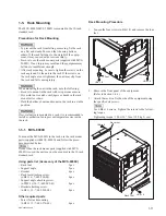
Page 17: ...table position w If several units are mounted in a rack it is recommended to install a ventilation fan to prevent temperature rise inside the rack 1 5 1 MVS 8000X To mount the MVS 8000X in the rack use the rack mount parts supplied with MVS 8000X and follow the proce dure described below n If other than the rack mount parts supplied with MVS 8000X is used the unit may not be mounted in the 19 inch...

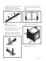
Page 18: ... eight screws The illustration below shows the left adapter 7 Tighten the screws PSW4 x 10 four screws each on the right and left for adjusting the length of the adapter completely the screws that were loosened in step 5 PSW4 s 10 PSW4 s 10 B4 s 10 B4 s 10 31 75 15 9 Front side Rear side Unit mm 8 Align the groove of the rack tool at the side of the equipment with the rail and slide the equipment ...

Page 19: ...682 560 09 6 pcs Adapter attaching screw B4 x 10 7 682 560 10 6 pcs Other requlred parts To mount in the rack the rack mount kit RMM 10 and the following part are required Screw for rack mounting B5 x 12 7 682 576 09 4 pcs Rack Mounting Procedure 1 Loosen the four screws B4 x 8 and remove the four feet Feet Feet B4 x 8 B4 x 8 2 Remove the front panel of the equipment Refer to Section 1 4 1 3 Attac...

Page 20: ...screws The figure bellow shows the left adapter B4 x 10 31 75 31 75 1U 4U 8U Unit mm B4 x 10 6 Tighten the screws B4 x 6 two screws each on the right and left for adjusting the length of the adapter completely the screws that were loosened in step 4 7 Align the groove of the rack tool at the side of the equipment with the rail and slide the equipment to the rear n The rack tools are hooked on the ...

Page 21: ...144 ME1 to ME4 PP 1 to 4 FC1 IN 1 to 8 FC2 IN 9 to 16 FC OUT 1 to 4 MSD1 2 1 2 REF IN BNC 75 Ω Belden 1694 coaxial cable _ REMOTE 1 to 4 D sub 9 pin Female D sub 9 pin Male Connector 9 pin Male Junction Shell 9 pin 1 560 651 00 1 1 561 749 00 GPI D sub 25 pin Female 1 2 D sub 25 pin Male D sub 25 pin Male Connector 25 pin Male Junction Shell 25 pin 1 560 904 11 1 1 563 377 11 NETWORK A CTRL NETWOR...

Page 22: ...1 2 REF IN BNC 75 Ω Belden 1694 coaxial cable _ REMOTE 1 to 4 D sub 9 pin Female D sub 9 pin Male Connector 9 pin Male Junction Shell 9 pin 1 560 651 00 1 1 561 749 00 GPI D sub 25 pin Female 1 2 D sub 25 pin Male D sub 25 pin Male Connector 25 pin Male Junction Shell 25 pin 1 560 904 11 1 1 563 377 11 NETWORK A CTRL NETWORK B DATA FM DATA RJ 45 Modular Jack 2 _ _ FM DEVICE 1 2 USB TypeA Receptacl...

Page 23: ... 8 7 GPI OUT 1B General purpose relay output B 1 8 GPI OUT 2B 9 GPI OUT 3B 10 GPI OUT 4B 11 GPI OUT 6 General purpose open collector output 2 12 GPI OUT 8 13 GPI OUT COM Ground for open collector output 14 GND Ground 15 GPI IN 1 General purpose input 16 GPI IN 3 17 GPI IN 5 18 GPI IN 7 19 GPI OUT 1A General purpose relay output A 1 20 GPI OUT 2A 21 GPI OUT 3A 22 GPI OUT 4A 23 GPI OUT 5 General pur...

Page 24: ... C 4 FM DATA 100BASE TX 1000BASE T RJ 45 8 pin 8 1 External view Pin No Signal Name Function 1 TRX1 Transmitted Received data 2 TRX1_ Transmitted Received data _ 3 TRX2 Transmitted Received data 4 TRX3 Transmitted Received data 5 TRX3_ Transmitted Received data _ 6 TRX2_ Transmitted Received data _ 7 TRX4 Transmitted Received data 8 TRX4_ Transmitted Received data _ 4 Installed only in MVS 8000X N...

Page 25: ...D2203 D2202 D2201 D2304 D2303 D2302 D2301 D2701 D2702 D2703 D2802 D2901 D2902 D2903 D3002 D2704 D2705 D2706 D2801 D2904 D2905 D2906 D3001 D2707 D2708 D2709 D2803 D2907 D2908 D2909 D3003 D3604 D3603 D3602 D3601 D3605 D3606 D3607 D3701 D3702 D3703 D3704 D4101 D4102 D4103 S501 S2201 S2202 S2302 S2301 D403 D402 D401 Side A Component Side D100 D101 D200 A B 1 2 SG 272 S500 S300 D202 D201 D200 A B C D E...

Page 26: ... IC1 IC5 does not start up properly D402 F 1 CA RESET A The board reset status indication Lights when the follow ing occurs When S401 S402 is pressed When 12 V 3 3 V or 1 2 V 1 power is not properly supplied When a reset request is made from software When IC1 IC5 does not start up properly D403 F 1 SWER RESET System reset status indication Lights when the following occurs When S402 is pressed When...

Page 27: ...en linked and blinks when communicating D2704 to D2706 D2801 D2904 to D2906 D3001 A 2 B 2 100 P0 to P7 Ethernet communication status indication for internal communications Lights when linked by 100base TX D2701 to D2703 D2802 D2901 to D2903 D3002 A 2 B 2 1000 P0 to P7 Ethernet communication status indication for internal communications Lights when 1000base T link is established P0 to P7 indicate p...

Page 28: ... mode of NEP1 In the default settings when shipped from the factory bit 8 is set to ON and others are set to OFF S2301 H 7 NEP2 RESET Reset the NEP2 S2302 J 7 NEP2 SET Sets the start up mode of NEP2 In the default settings when shipped from the factory bit 8 is set to ON and others are set to OFF LED on the CPU DP Module D1 L 6 3 3 V Power supply status indication Lights when 3 3 V power is suppli...

Page 29: ...ll OFF LED on the SG 272 board D100 B 1 REF OK status LED Lights when detected the V sync of the reference input D101 B 1 REF EXT status LED Lights when the synchronize signal input to the reference input D200 B 1 LOCK status LED Lights when synchronized to the reference signal LED on the SIO 26 board D200 A 3 Communication error indication Lights when the communication error is occurred through t...

Page 30: ...6 5 4 3 2 1 A B C D E F G H D1 D3 D5 D2 D4 D16 D17 D11 D10 D9 D8 D7 D15 D14 D13 D12 D6 SW2 LED D201 B 1 1 0 V 1 0 V power supply status indication Lights when the 1 0 V power is supplied D202 A 1 12 V 12 V power supply status indication Lights when the 12 V power is supplied If this LED does not light the fuse may have blown D203 A 1 1 2 V 1 1 2 V 1 power supply status indication Lights when the 1...

Page 31: ...ly D801 F 6 IC1 ERR Error status indication of IC1 Lights when the configura tion error is occurred D802 to D804 E 4 F 4 IC1 STAT IC1 error status indication Indicates the internal status For maintenance D917 to D920 P 1 ND901 N 1 ND902 P 1 CPU STATUS CPU software status indication D1101 E 1 REF EXT REF IN status indication Lights when REF signal is not input to the REF IN termi nal Turn off when ...

Page 32: ...re mode Default setting when shipped from the factory is all OFF S902 G 1 GROUP ID Sets the GROUP ID for connecting LAN Do not change the setting In the default settings when shipped from the factory bit 1 is set to ON and others are set to OFF S903 G 1 UNIT ID Sets the UNIT ID for connecting LAN Do not change the setting In the default settings when shipped from the factory bit 1 is set to ON and...

Page 33: ...e of CPU DP module Default setting when shipped from the factory is all OFF LED on the SG 272 board D100 B 1 REF OK status LED Lights when detected the V sync of the reference input D101 B 1 REF EXT status LED Lights when the synchronize signal input to the reference input D200 B 1 LOCK status LED Lights when synchronized to the reference signal LED on the SIO 26 board D200 A 3 Communication error...

Page 34: ...3 D12 D6 SW2 Side A Component Side LED D719 B 1 POWER Power supply status indication Lights in green when all power supply on the board are normally D203 C 1 12 V 12 V power supply status indication Lights when the 12 V power is supplied If this LED does not light the fuse may have blown D301 D302 D303 F 1 1 0 V 1 2 3 1 0 V power supply status indication Lights when the 1 0 V power is supplied D30...

Page 35: ... and blinks when data send or receive is in progress D1401 E 1 CAD2 Indicates the configuration error of the FPGA If this LED lit the FPGA IC21 can possibly be working incorrectly D1402 G 1 CONF ERR Indicates the configuration error of the FPGA If this LED lit any FPGA can possibly be working incor rectly D1403 F 1 WPG Indicates the configuration error of the FPGA If this LED lit the FPGA IC10 can...

Page 36: ...ndicates the configuration error of the FPGA If this LED lit the FPGA IC2 can possibly be working incorrectly Switch S501 K 1 RST Reset the MIX board Pressing this switch initializes the MIX board S901 L 1 MON For monitor switch used in maintaining through the termi nal pin S902 M 1 CPU RESET This is a reset switch used for design LED on the CPU DP Module Refer to LED on the CPU DP module in 1 CA ...

Page 37: ...e LED D203 C 1 12 V 12 V power supply status indication Lights when the 12 V power is supplied If this LED does not light the fuse may have blown D301 D302 D303 D 1 1 0 V 1 2 3 1 0 V power supply status indication Lights when the 1 0 V power is supplied D304 D 1 1 2 V 1 2 V power supply status indication Lights when the 1 2 V power is supplied D305 C 1 1 8 V 1 8 V power supply status indication Li...

Page 38: ...d D1104 B 1 BECON For future expansion D1201 D1202 F 1 CNF ERR Indicates the configuration error of the FPGA If this LED lit any FPGA can possibly be working incor rectly D2701 to D2708 E 1 F 1 1 0V AVCC1 to 8 1 0 V analog power supply status indication Lights when the 1 0 V power is supplied D2709 to D2716 E 1 F 1 1 2V APLL1 to 8 1 2 V analog power supply status indication Lights when the 1 2 V p...

Page 39: ...dication Lights when the 12 V power is supplied If this LED does not light the fuse may have blown D301 D302 D303 D 1 1 0 V 1 2 3 1 0 V power supply status indication Lights when the 1 0 V power is supplied D304 D 1 1 2 V 1 2 V power supply status indication Lights when the 1 2 V power is supplied D305 C 1 1 8 V 1 8 V power supply status indication Lights when the 1 8 V power is supplied D306 C 1 ...

Page 40: ...PGA If this LED lit the PLL can possibly be unlocked D1104 B 1 BECON For future expansion D1201 D1202 F 1 CNF ERR Indicates the configuration error of the FPGA If this LED lit any FPGA can possibly be working incor rectly D2701 to D2708 E 1 F 1 1 0V AVCC1 to 8 1 0 V analog power supply status indication Lights when the 1 0 V power is supplied D2709 to D2716 E 1 F 1 1 2V APLL1 to 8 1 2 V analog pow...

Page 41: ...indication Lights when the 12 V power is supplied If this LED does not light the fuse may have blown D401 D 1 1 2 V 2 1 2 V 2 power supply status indication Lights when the 1 2 V power is supplied D403 D 1 3 3 V 3 3 V power supply status indication Lights when the 3 3 V power is supplied D1101 E 1 CONF ERR Indicates the configuration error of the IC601 If this LED lit the IC601 can possibly be wor...

Page 42: ...ssing this switch initializes the board S701 K 1 MON The reset switch that is used to reset the monitor during maintenance through the terminal Valid only for the XPT 31 board S1102 J 1 CPU RESET Pressing this switch initializes only the CPU on the circuit board Valid only for the XPT 31 board LED on the CPU DP Module Refer to LED on the CPU DP module in 1 CA 82 board CPU DP is installed only on t...

Page 43: ...ly status indication Lights when the 1 0 V power is supplied D304 K 1 1 2 V 1 2 V power supply status indication Lights when the 1 2 V power is supplied D305 K 1 1 8 V 1 8 V power supply status indication Lights when the 1 8 V power is supplied D306 J 1 3 3 V 3 3 V power supply status indication Lights when the 3 3 V power is supplied D401 B 10 IC402 lock status indication Indicates lock unlock of...

Page 44: ... possibly be work ing incorrectly D618 C 1 STATUS For future expansion D619 C 1 BECON For future expansion D620 B 1 POWER Power supply status indication Lights in green when all power supply on the board are normally If the power supply has abnormality turns off Switch S602 F 1 RST Pressing this switch initializes the board ...

Page 45: ...future expansion D801 C 1 STATUS For future expansion D203 C 1 12 V 12 V power supply status indication Lights when the 12 V power is supplied If this LED does not light the fuse may have blown D307 C 1 3 3 V 3 3 V power supply status indication Lights when the 3 3 V power is supplied D305 D306 C 1 2 5 V 1 2 2 5 V power supply status indication Lights when the 2 5 V power is supplied D304 C 1 1 8 ...

Page 46: ...er 2 can possibly be unlocked D1307 E 1 SDI1 Indicates the configuration error of the FPGA If this LED lit the FPGA IC2 can possibly be working incorrectly D1304 E 1 SDI2 Indicates the configuration error of the FPGA If this LED lit the FPGA IC3 can possibly be working incorrectly D1306 E 1 FC1 2 Indicates the configuration error of the FPGA If this LED lit the FPGA IC4 can possibly be working inc...

Page 47: ...K 1 2 5 V 2 5 V power supply status indication Lights when the 2 5 V power is supplied D501 D502 K 1 1 8 V 1 2 1 8 V power supply status indication Lights when the 1 8 V power is supplied D451 K 1 1 2 V PLD 1 2 V power supply status indication Lights when the 1 2 V power is supplied LED D3602 B 1 POWER Power supply status indication Lights in green when all power supply on the board are normally D...

Page 48: ...PU module with the CA board and receiving transmitting the data D4002 G 1 EXT LINK ACT Lights when the FM DATA LAN linked and blinks when communicating D3605 to D3620 N 1 CPU STATUS Indicates CPU status on board D3500 G 1 CC_UNLOCK Indicates lock unlock of the clock conditioner If this LED lit the clock conditioner can possibly be unlocked Switch S3100 J 1 RST This is reset switch for the MY board...

Page 49: ...504 D1505 D1508 D501 LED D719 B 1 POWER Power supply status indication Lights in green when all power supply on the board are normally D203 H 1 12 V 12 V power supply status indication Lights when the 12 V power is supplied If this LED does not light the fuse may have blown D301 K 1 1 0 V 1 0 V power supply status indication Lights when the 1 0 V power is supplied D302 D303 D309 K 1 1 1 V 1 2 3 1 ...

Page 50: ... with CA board and blinks when data send or receive is in progress D903 L 1 INET DME LINK For test LED D904 L 1 INET DME ACT For test LED D1509 J 1 CAD2 Indicates the configuration error of the FPGA If this LED lit the FPGA IC21 can possibly be working incorrectly D1510 K 1 CONF ERR Indicates the configuration error of the FPGA If this LED lit any FPGA can possibly be working incor rectly D1502 J ...

Page 51: ...g incorrectly Switch S501 G 1 RST Reset the DVP board Pressing this switch initializes the DVP board S801 G 1 MON For monitor switch used in maintaining through the termi nal pin LED on the CPU DP Module Refer to LED on the CPU DP module in 1 CA 82 board Switch on the CPU DP Module Refer to Switch on the CPU DP module in 1 CA 82 board ...

Page 52: ... Pack The illustration represents the MVS 8000X b a It is recommended that the CTRL and DATA LAN networks be configured by connecting separate Ethernet switches for each LAN c Terminate with the supplied 75Ω terminators d This figure shows the rear panel when one MKE 8021A is installed in the MVE 8000A e The following cannot be used for connection to the MVS 8000X MVS 7000X Model Relevant serial n...

Page 53: ... d Key signal Video input signal Video output signal AC power supply V K IN SDI OUT 1 2 DME OUTPUTS 1 20 PRIMARY INPUTS 1 144 OUTPUTS 1 48 DME INPUTS 1 20 SDI OUT 1 2 A B SDI OUT 1 2 A B SDI OUT 1 2 SDI OUT 1 2 V K OUT V K OUT V K IN Video signal MVS 8000X Multi Format Switcher Processor a The illustration represents the MVS 8000X b a For the AC power cord refer to the MVE 8000A Operation Manual c...

Page 54: ......

Page 55: ... boards installed into the specified slots Install the standard boards into the specified slots Refer to the MVS 8000X Maintenance Manual Install the option boards into the specified slots Refer to Section 1 4 Are the option boards installed into the specified slots Are the input and output cables connected correctly NO Install the software correctly Refer to the User s Guide Is the Software insta...

Page 56: ...se inside the machine This may have an adverse effect on performance and the life of the machine Cleaning of the fan every month is recommended Contact your local Sony Sales Office Service Center for informa tion on cleaning the fan Fan This figure shows MVS 8000X 2 3 About the Data Backup Capacitor A large capacitor is installed on the CA 82 board MVS 8000X or the CA 82A board MVS 7000X in order ...

Page 57: ...el consiste en informations qui sont la propriété de Sony Corporation Sony Corporation interdit formellement la copie de quelque partie que ce soit de ce manuel ou son emploi pour tout autre but que des opérations ou entretiens de l équipement à moins d une permission écrite de Sony Corporation Das in dieser Anleitung enthaltene Material besteht aus Informationen die Eigentum der Sony Corporation ...

Page 58: ...Sony Corporation MVS 7000X SY MVS 8000X SY E 4 189 509 03 Printed in Japan 2011 5 08 2010 ...

Reviews: