background image

107

Monitoring the Local and Remote Pictures at the Same Time – PandP/Side by Side Feature

C

h

a

p

te

r 3:

 B
a

si

c

 C
o

nn
ect
ion

Monitoring the Local and Remote 
Pictures at the Same Time – PandP/Side 
by Side Feature

You can display the local and remote pictures at the same time on the monitor 
screen.

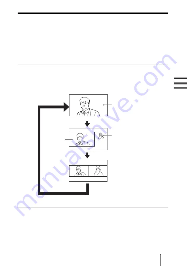
To display twin pictures

Press the DISPLAY button on the Remote Commander during communication 
with a remote party.
Each press of the button changes the display on the monitor screen as follows:

To swap the left and right pictures

Press the FAR/NEAR button on the Remote Commander to display the 
Display Control menu. Changing the setting under “Display” (Far or Near) 
swaps the left and right pictures.

Local picture

Remote picture

Remote 
picture

PandP (Picture-
and-Picture) 
mode

Full screen mode

Side by Side 
mode

Summary of Contents for IPELA PCS-HG90

Page 1: ...2006 Sony Corporation 3 991 626 15 1 Video Communication System Operating Instructions Version 2 2 Before operating the unit please read this manual thoroughly and retain it for future reference PCS HG90 ...

Page 2: ...osion use R6 size AA manganese or alkaline batteries CAUTION RISK OF EXPLOSION IF BATTERY IS REPLACED BY AN INCORRECT TYPE DISPOSE OF USED BATTERIES ACCORDING TO ALL APPLICABLE LOCAL REGULATIONS For the customers in the USA WARNING This equipment has been tested and found to comply with the limits for a Class A digital device pursuant to Part 15 of the FCC Rules These limits are designed to provid...

Page 3: ...uld occur consult your nearest authorized Sony service facility Voor de Klanten in Nederland If you dispose the unit consult your nearest Sony Service Center The built in battery must be treated as a chemical waste Für Kunden in Deutschland Entsorgungshinweis Bitte werfen Sie nur entladene Batterien in die Sammelboxen beim Handel oder den Kommunen Entladen sind Batterien in der Regel dann wenn das...

Page 4: ...1 Attaching the Remote Control Receiver 21 Inserting Batteries into the Remote Commander 22 Turning the System On Off 24 Turning On 24 Standby Mode Function 26 Setting the Video Communication System to Standby Mode 26 Turning Off 27 Adjusting the Volume on the TV Monitor 27 Displaying Help 28 Displaying the Versions 28 Setting Up the System for the First Time Initial Setup Wizard 29 Using the Menu...

Page 5: ...Router 66 LAN Connecting through a Gatekeeper 67 LAN Connecting through NAT 68 LAN PPPoE Connections 69 Measuring the Network Quality 71 Setting the Transmitting Image Quality 74 Chapter 3 Basic Connection Starting a Communication by Calling a Remote Party 76 Turning on the Power 76 Using the Launcher Menu 77 Displaying the Launcher Menu During Communication 80 Calling a Remote Party 81 Receiving ...

Page 6: ...ry Stick 111 Formatting a Memory Stick 113 Chapter 4 Connection With Optional Equipment Using a Monitor Exclusively for Local Pictures 115 Using Multiple Microphones 117 Using the Echo Canceling Microphones 120 Using the Second Camera Unit 123 Recording During a Communication 124 Sending Audio Video from the External Equipment to a Remote Party 125 Chapter 5 Encrypted Connection Preparing for an E...

Page 7: ...er to Peer Connection 149 For Multipoint Connection 150 How to use Phone Book 151 Phone Book Edit page 152 Phone Book New page 153 How to use Setup 154 Send Message page 156 Erase page 157 How to use Info 158 Cause Code list page 159 Call Log page 160 Monitor a Meeting Over the Web 161 Appendix Location and Function of Parts and Controls 162 PCS PHG90 Communication Terminal 162 PCSA CHG90 Camera U...

Page 8: ...SA A7P4 Microphone 4 pack optional 180 Acceptable RGB Input Output Signals 181 Pin Assignments 182 List of Port Numbers Used on the PCS HG90 184 Video Communication Room Layout 185 Camera Range 185 Memory Stick Media 186 Glossary 188 Menu Configuration 190 ...

Page 9: ... Chapter 3 Basic Connection This chapter guides you through the basic operations and settings for connecting to a remote party You will learn how to connect from start to finish It is recommended that this chapter be read by participants in connection Chapter 4 Connection With Optional Equipment This chapter shows advanced connection using the optional equipment Chapter 5 Encrypted Connection This...

Page 10: ...deo input output allowing shooting transmission and reception of digital signal It is also equipped with XLR type audio input output connectors enabling connection with audio equipment for professional use QoS Quality of Service function for optimization of bandwidth and traffic packet through network The system includes Packet Resend Request Adaptive Rate Control and Forward Error Control functio...

Page 11: ...tem It contains the following components Basic System Components Unit Description PCS PHG90 Communication Terminal Contains the video codec audio codec echo canceler network interfaces and system controller PCSA RG1 Remote Commander Used to operate the Communication Terminal and Camera Unit AC power cord Supplies power to the Communication Terminal Remote Control Receiver Connects to the Communica...

Page 12: ...jector etc Used as a monitor and speakers Unit Description PCSA CHG90 Camera Unit Camera unit especially designed for use with the PCS HG90 PCS A1 Microphone Omni directional microphone that picks up sound relatively from all directions allowing participants to speak from any location It is recommended to use in a quiet situation PCSA A3 Microphone Unidirectional microphone It is recommended when ...

Page 13: ... Canceling Microphone Narrow coverage monaural microphones that feature high sound quality and a built in echo canceler Several PCSA A7 microphones can be connected in cascade without losing sound quality Recommended when using several microphones 4 piece set Unit Description ...

Page 14: ...mples This allows you to Hold a peer to peer connection over LAN Pick up the sound of a communication in stereo by connecting two external microphones System configuration System Configuration for Peer to Peer Connection ON LINE POWER STANDBY LAN ALERT ON LINE POWER STANDBY LAN ALERT 1 PCS PHG90 Communication Terminal 2 PCSA CHG90 Camera Unit not supplied 3 PCSA RG1 Remote Commander 4 Remote Contr...

Page 15: ...tem Configuration for Multipoint Connection ON LINE POWER STANDBY LAN ALERT ON LINE POWER STANDBY LAN ALERT ON LINE POWER STANDBY LAN ALERT ON LINE POWER STANDBY LAN ALERT 1 PCS PHG90 Communication Terminal 2 PCSA CHG90 Camera Unit not supplied 3 PCSA RG1 Remote Commander 4 Remote Control Receiver 5 TV monitor not supplied 6 PCSA A3 Microphones not supplied 2 pieces ...

Page 16: ... participants When using speakers do not place them in front of the microphones PCSA A7 echo canceling microphone is monaural type For information about PCSA A7 Microphones see Using the Echo Canceling Microphones on page 120 System Configuration Using the PCSA A7 Echo Canceling Microphones Notes ON LINE POWER STANDBY LAN ALERT ON LINE POWER STANDBY LAN ALERT 1 PCS PHG90 Communication Terminal 2 P...

Page 17: ...0BASE T connector Be sure to connect the Camera Unit to the Communication Terminal using both the BNC and VISCA cables The picture from the camera cannot be viewed if it is directly connected to a TV monitor The REC OUT MIXED connectors are used to make an audio recording These are not used normaly Caution System Connection Notes RGB AUX CONTROL CAMERA CONTROL 100BASE TX 10BASE T VISCA AC IN SUB M...

Page 18: ...UX 2 R MIC EC MIC A7 1 2 A1 A3 PLUG IN POWER 1 R 2 L L R L AUX 1 L L PCSA CHG90 Camera Unit Power cord supplied PCS PHG90 Communication Terminal to a wall outlet to LAN to VISCA RS 232C IN to MIC A1 A3 TV monitor not supplied UTP cable category 5 straight not supplied to video inputs to AC outlet PCSA A3 or PCS A1 microphones not supplied to AC outlet to HD SDI to VIDEO OUT YPbPr to AUDIO OUT R L ...

Page 19: ...ct either the VISCA RS 232C or VISCA RS 422 connector on the Camera Unit to the CAMERA CONTROL VISCA MAIN or SUB connector VISCA RS 232C When connecting distance is within 15 m 49 ft VISCA RS 422 When connecting distance is between 15 m 49 ft and 100 m 328 ft To set the RS 232C RS 422 select switch Before making the remote control connection be sure to select RS 232C or RS 422 with Switch 2 of the...

Page 20: ...s for the optional converter prepare plugs that match the connectors on the converter When using the VISCA RS 422 connector check that the BOTTOM switch on the bottom of the Camera Unit is set to RS 422 Notes VISCA RS 422 1 2 3 4 5 6 7 8 9 VISCA RS 232C OUT DC IN 12V R HFBK HD1 MONITOR HD SDI RGB AUX CONTROL CAMERA CONTROL 100BASE TX 10BASE T VISCA AC IN SUB MAIN CTRL S REC OUT MIXED AUDIO OUT R L...

Page 21: ...te sensor of the remote control receiver When an inverter type or brightness adjustable type of fluorescent lamp is used the sensitivity of the Remote Commander may deteriorate If the Remote Commander does not function attach the supplied filter over the remote sensor of the remote control receiver see page 22 or change the location of the remote control receiver to avoid direct light Attaching th...

Page 22: ...mmunication System can be controlled with the supplied Remote Commander 1 Remove the battery compartment cover 2 Insert two size AA R6 batteries supplied with correct polarities into the battery compartment Be sure to insert the batteries E side first Inserting them forcibly e side first may damage the insulated film covering the batteries and cause a short circuit Inserting Batteries into the Rem...

Page 23: ...sible battery leakage or corrosion observe the following Make sure to insert the batteries with the polarities in the correct direction Do not mix old and new batteries or different types of batteries Do not attempt to charge the batteries If you do not intend to use the Remote Commander for a long period of time remove the batteries If battery leakage occurs clean the battery compartment and repl...

Page 24: ...s in green then changes to light On the Camera Unit first the STANDBY indicator lights in orange then the POWER indicator Lights in green The launcher menu will appear on the monitor screen after the IPELA logo appears and the picture shot by the local camera will also appear in the launcher menu Launcher menu Turning On POWER STANDBY indicator Lights in green 1 Power switch POWER indicator Lights...

Page 25: ...set to 1080 60i at the factory If the video format set on the TV monitor is different from that on the Communication Terminal no picture appears on the TV monitor Check the video format setting on the TV monitor and if necessary change the video format setting on the Communication Terminal To change the video format on the Communication Terminal Use the FAR NEAR button and number buttons 1 2 and 3...

Page 26: ...dby appears on the monitor screen 2 Press the B or b button on the Remote Commander to select OK and press the PUSH ENTER button You may press the 1 button on the Remote Commander The Video Communication System enters standby mode and the STANDBY indicator on the Camera Unit and the POWER STANDBY indicator on the Communication Terminal light in orange When the Communication Terminal and the Camera...

Page 27: ...ication Terminal flashes 2 Press the 1 power switch again within five seconds The power of the system is turned off 3 Turn off the power of other equipment Set the power switch on the Communication Terminal off when the system will not be used for an extended period While the power switch is off you cannot receive a call from a remote party Disconnect the power cord from the AC outlet after the po...

Page 28: ...nder displays help to guide most operations in the guidance area You can hide the help used for entering characters Press the MENU button on the Remote Commander to show the menu and set Character Input Help under Menu Screens of the General Setup menu to Off See page 48 You can check the version IP address etc of the Communication Terminal by displaying the Machine Information menu on the monitor...

Page 29: ... Auto Automatically assigns your IP address network mask gateway address and DNS address Off Deactivates DHCP In this case set your IP address network mask gateway address and DNS address manually Host Name Enter your host name up to 30 characters IP Address Enter your IP address Network Mask Enter your network mask Gateway Address Enter your default gateway address DNS Address Enter your DNS Doma...

Page 30: ...em appear 5 Press the V or v button to select an item from the list then press the PUSH ENTER button For items that require to enter characters and figures press the Remote Commander button enter the desired characters and figures and then press the PUSH ENTER button 6 Press the v button to select Save then press the PUSH ENTER button The selected setting is saved and the display returns to the pr...

Page 31: ...31 Using the Menus Chapter 1 Installation and Preparation To return to the previous menu Press the RETURN button on the Remote Commander ...

Page 32: ...5 12 28 12 34 2005 12 27 06 12 PM Room 11B LAN 255 255 254 128 2005 12 28 09 00 AM Room 10A LAN 255 255 255 255 2005 12 27 02 52 PM Room 12A LAN 255 255 253 64 2005 12 27 11 11 AM Room 12B LAN 255 255 253 32 2005 12 26 04 28 PM Room 16A LAN 255 255 249 16 Auto Track Stop Camera 2005 12 28 12 34 Preset Save Preset Load Adjustments HD SDI Dial Setup Cancel Save 2005 12 28 12 34 Off 1 1 More Options ...

Page 33: ...ONNECT DISCONNECT button on the Remote Commander For details on the Detailed Dial menu see pages 81 to 84 History This menu is used to display the communication history information The menu appears when you select History on the launcher menu For details on the History see page 85 Capture Room 10A Room 11B Room 12A Room 01 IP 255 255 255 255 2005 12 28 12 34 Menu Phone Book Detailed Dial History E...

Page 34: ... text box in the menu using the Remote Commander To enter letters or numbers 1 Press the FAR NEAR ALPHA NUM button repeatedly to enable the letters or numbers to be input 2 Press the number buttons repeatedly to enter the letters or numbers that you want You can enter the letter shown on each button by pressing it repeatedly You can enter the number shown on each button by pressing it Auto Track S...

Page 35: ...address Press the button To delete a character Press the PinP BACK SPACE button The last entered character is deleted To delete all characters in a line Move the cursor to the line to be deleted then press the DISPLAY CLEAR button When you press the HELP button on the Remote Commander to show helps you can hide only the help used for entering characters Set Character Input Help of Menu Screens in ...

Page 36: ... 38 Status Status menu see page 39 Audio Audio Setup menu see page 41 Video Video Setup menu see page 43 General General Setup menu see page 47 Administrator Administrator Setup menu see page 50 LAN LAN Setup menu see page 54 Encryption Encryption Setup menu See page 59 Information Machine Information menu see page 59 2 Use the V v B or b button on the Remote Commander to select the menu you want ...

Page 37: ...see Call Log page on page 160 Select LAN Prefix Allows you to select whether to use the LAN prefix Enable Enable the LAN prefix Disable Disable the LAN prefix LAN Prefix The information entered into this box is added to the beginning of the IP address Select whether to use the LAN prefix in the Select LAN Prefix option The Answer menu is used to set up call reception Auto Answer Allows you to sele...

Page 38: ... are set to Individual Settings individual setting items are displayed Communication Bit Rate Allows you to select Communication Bit Rate for a point When Peer to Peer Multipoint and Transmission Reception Bit Rate on page 1 2 are set to Individual Settings you can configure Peer to Peer Multipoint and Transmission Reception individually You can select from among 2Mbps 2 5Mbps 3Mbps 4Mbps 5Mbps 6M...

Page 39: ...receives audio matching the compression format of the remote site AAC Monaural 48K Sends or receives audio based on the MPEG4 AAC monaural format 48K AAC Monaural 96K Sends or receives audio based on the MPEG4 AAC monaural format 96K AAC Stereo 48K Sends or receives audio based on the MPEG4 AAC stereo format 48K AAC Stereo 96K Sends or receives audio based on the MPEG4 AAC stereo format 96K G 728 ...

Page 40: ...s Bit rate Encode Displays the transfer rates for sending data by category audio and video Bit rate Decode Displays the transfer rates for receiving data by category audio and video Number of packets Lost Displays the number of packets lost during transfer on the network by category audio and video Number of packets Recovered Displays the number of lost packets that were recovered with the system ...

Page 41: ... the AUDIO IN AUX2 connectors HD SDI Inputs audio from external equipment connected to the HD SDI 1 or HD SDI 2 connector When the HD SDI 2 is selected in the Video Setting menu the audio from the HD SDI 2 connector is input When the other setting is selected the audio from the HD SDI 1 connector is input Input Mode Allows you to select the audio input mode Stereo Inputs audio to the AUDIO IN R an...

Page 42: ...e echo canceler is effective for the microphones connected to the AUDIO IN MIC connectors or MIC A1 A3 jacks Audio Output Delay Setting Allows you to set Audio Output Delay to synchronize the audio with the video output Default 100ms Selects the default delay 100ms Default 50ms Selects the default delay 50ms Default Selects the default delay Default 50ms Selects the default delay 50ms Default 100m...

Page 43: ...uts the ringer tone Off Does not output the ringer tone The following menus appear when you select Video on the Setup menu Select the desired menu Video Input Output Link to Audio Input Allows you to switch the audio input in conjunction with switching the video input by linking each video input and a specific audio input On Links switching of the video input and the audio input Off Switches the v...

Page 44: ... connector When the HD SDI 2 is selected in the Video Setting menu the audio from the HD SDI 2 connector is input When other setting is selected the audio from the HD SDI 1 connector is input Video Format Output Video Format Allows you to select 720 or 1080 Frequency Allows you to select the video input output frequency 50 Hz or 60 Hz When Frequency is set to 50 Hz you have to set the camera signa...

Page 45: ... communication bit rate Detailed Setup Set each item individually Motion Smoothing Filter Select the intensity of the motion smoothing filter temporal filter Auto The intensity of the motion smoothing filter is adjusted automatically according to the communication bit rate Off The motion smoothing filter is deactivated Low The motion smoothing filter is set to low Medium The motion smoothing filte...

Page 46: ...blished The pattern can be switched by using the buttons on the Remote Commander during communication Full Screen Displays the local picture shot by the local camera in full screen PandP Displays the local and remote pictures in PandP mode Side by Side Displays the local and remote pictures in Side by Side mode For details on PandP or Side by Side mode see Monitoring the Local and Remote Pictures ...

Page 47: ...e camera control command transmitted by the remote party On Accepts the camera control command Off Rejects the camera control command Standby Mode Allows you to select whether the Communication Terminal enters standby mode if idle for a specified period of time On Allows the system to go on standby Off Does not allow the system to go on standby Standby Time Specify the time the system must remain ...

Page 48: ...he terminal names Show temporarily Displays the terminal names for a brief moment Always on Displays the terminal names Character Input Help Allows you to select whether to display help text in the guide area when entering characters and numbers On Displays help Off Does not display help Guide On Displays the guide Off Does not display the guide Indicator On Displays the indicators Off Does not di...

Page 49: ...hone Book Button On Displays Direct Phone Book Off Does not display Direct Phone Book Direct Dial On Displays the Direct Dial text box Off Does not display the Direct Dial text box Clock Display On Displays the current date and time Off Does not display the current date and time Local Terminal Name On Displays your terminal name Off Does not display your terminal name Capture Button On Displays Ca...

Page 50: ...trator Password Set the system administrator password up to 8 characters This allows the system administrator to modify AdministratorSetup and Phone Book menu items Be aware that setting other passwords but leaving the system administrator password blank allows modification and connection without password input Phone Book Modification Password Set the password used to modify the Phone Book up to 8...

Page 51: ...eed for the password when saving the LAN Setup settings Encryption Setup Enable No need for the pass word when saving the Encryption Setup settings Disable Need for the password when saving the Encryption Setup settings Phone Book Page 1 2 Save Phone Book Allows you to save the data in the Phone Book on a Memory Stick The data already on the Memory Stick is then overwritten Load Phone Book Allows ...

Page 52: ...tup Saves the data for each setting to a Memory Stick The data for each setting saved on the Memory Stick is overwritten Phone Book and History data are not saved Load Setup Loads the data for each setting from a Memory Stick The data for each setting saved on the unit is overwritten When saving and loading settings make sure that the version of the terminal from which the data was originally save...

Page 53: ...y measurement The load and stress test is possible only when the remote terminal is PCS HG90 with version 2 2 or later Start Measurement Select this button to start the network quality measurement The network quality measurement will take several minutes depending on the selected measurement items Result of Network Quality Measurement Page 2 4 The result of the network quality measurement is shown...

Page 54: ...ral Page 1 2 DHCP Mode Allows you to select whether the Dynamic Host Configuration Protocol DHCP server is enabled Auto The IP address network mask and gateway and DNS addresses are automatically assigned You should confirm the assigned IP address in the launcher menu or the Machine Information menu after the LAN connection is established Off Disables the DHCP server In this case enter an IP addre...

Page 55: ...eper used when Gatekeeper Mode is set to On User Alias Enter the user name H 323 alias registered in the gatekeeper User Number Enter the user number E 164 number registered in the gatekeeper SNMP SNMP Mode Allows you to select whether the Simple Network Management Protocol SNMP agent is enabled On Enables the SNMP agent Off Disables the SNMP agent Trap Destination Enter the address of the trap de...

Page 56: ...n PPPoE DNS Allows you to select whether to obtain DNS server addresses automatically or to specify them manually when connecting to a LAN using PPPoE Specify Allows you to specify DNS server addresses Obtain automatically Assigns DNS server addresses automatically Primary DNS Enter a primary DNS address Secondary DNS Enter a secondary DNS address NAT Port Page 1 2 NAT Mode Allows you to select wh...

Page 57: ... QoS When On is selected the system automatically switches the Front Error Correction the Packet Retransmission Request and the Adaptive Rate Control function according to the condition of the network On Switches automatically Off Does not switch automatically Allows you to set on or off for each function Forward Error Correction FEC Allows you to select whether received packets containing errors ...

Page 58: ...deo Configure the TOS field for video data Page 2 3 TOS Audio Configure the TOS field for audio data Page 3 3 TOS Camera Control Configure the TOS field for camera control signals TOS Allows you to select how to define the Type of Service TOS field Off Does not define the TOS field IP Precedence Defines the TOS field as IP Precedence Diffserve Defines the TOS field as Diffserve IP Precedence Enter...

Page 59: ...ction On Uses the encryption function Off Does not use the encryption function Encryption Mode Allows you to select the encryption mode Connect priority Connects by encryption with the party who can be connected by the standard encryption Connects without encryption with the party who cannot be connected by the standard encryptionorwhose standard encryption function is turned off Encryption priori...

Page 60: ...Entering Characters on page 34 4 Select the dial mode you are using to connect to a remote party with Dial Mode Single Register a remote party for a peer to peer connection Multipoint Register the remote parties for a multipoint connection The List Edit menu switches according to the selected Dial Mode For the procedure for registration in a multipoint connection see Registering the Remote Parties...

Page 61: ...in the Phone Book is terminated you can register this remote party to the Phone Book In this case the IP address is used as the name of the remote party Modify it if necessary To set up more detailed options Select the More Options button with the V v B or b button on the Remote Commander and press the PUSH ENTER button to open a menu for more detailed dial settings You can change the settings of ...

Page 62: ...tton on the Remote Commander to select OK then press the PUSH ENTER button The selected party is deleted To cancel deleting Select Cancel in step 4 then press the PUSH ENTER button You can register up to three remote parties in the Direct Phone Book in the launcher menu It is convenient if you register the parties to whom you often dial 1 Use the V v B or b button on the Remote Commander to select...

Page 63: ... Private Phone Book An empty folder and file for a Private Phone Book are created in the Memory Stick 4 Register a new remote party The procedure is the same as that for registering in the Phone Book Proceed with steps 2 to 7 in Registering a New Remote Party in the Phone Book on page 60 The procedures for how to change the contents of the Private Phone Book how to delete the registered remote par...

Page 64: ...he Memory Stick in which the Private Phone Book is registered 1 Open Page 2 2 in the Phone Book menu 2 Use the V v B or b button on the Remote Commander to select the remote party to dial automatically then press the PUSH ENTER button 3 Press the V or v button on the Remote Commander to select Edit then press the PUSH ENTER button The List Edit menu appears 4 Use the V v B or b button on the Remot...

Page 65: ...configurations consult with the system administrator Configuration example Set DHCP Mode to Auto under Page 1 2 of the General screen in the LAN Setup menu The setting has been configured properly if the IP address appears in the launcher menu To connect Select Single under Dial Mode enter the remote party s IP address and dial LAN Connecting via DHCP LAN1 LAN2 DHCP server 1 LAN Setup General Canc...

Page 66: ...operly if the correct IP address appears in the launcher menu To connect Select Single under Dial Mode enter the remote party s IP address and dial LAN Connecting Through a Router 192 100 10 10 Virtual Private Network VPN Router Router LAN 1 192 100 10 1 192 100 20 20 LAN 2 192 100 20 1 LAN Setup General Cancel Save 2005 12 28 12 34 Host Name Off DHCP Mode Network Mask IP Address DNS Address Gatew...

Page 67: ...correct IP address appears in the launcher menu and Gate Keeper Registration Confirmed appears on the lower part of the Input Output Peripheral status screen in the Status menu LAN Connecting through a Gatekeeper User number 100 LAN2 192 100 10 10 User alias PCS A Router Router User number 200 LAN1 192 100 10 1 192 100 20 20 Gatekeeper 192 100 10 20 192 100 20 1 User alias PCS B LAN Setup General ...

Page 68: ...iate values for IP Address Network Mask and Gateway Address 2 Set NAT Mode Page 1 2 to On in the NAT Port screen of the LAN Setup menu and enter the appropriate IP address in NAT Address The setting has been configured properly if the correct NAT address appears in the launcher menu LAN Connecting through NAT Internet 210 10 10 1 Router Router 210 20 20 2 Global address 192 168 10 10 192 168 10 1 ...

Page 69: ... Setup menu as they are not in a NAT environment To connect Select Single under Dial Mode enter the remote party s IP address and dial When using the terminal in the NAT environment you can connect to a remote party global IP but for a remote party to connect to you you must configure your router settings For details on router settings consult with the system administrator When using PPPoE you can...

Page 70: ...f the correct IP address appears in the launcher menu If the fixed DNS server address is specified by the provider set PPPoE DNS to Specify and enter the specific addresses in Primary DNS and Secondary DNS 3 Remote parties must configure in the same way To connect Select Single under Dial Mode enter the remote party s IP address and dial Note LAN Setup PPPoE Cancel Save 2005 12 28 12 34 1 2 Page P...

Page 71: ...up menu see the Network Quality Measurement screen in the Administrator Setup menu page 52 For the network quality measurement knowledge of the network is necessary Consult your network administrator or Sony dealer Before measurement On the remote terminal to be measured make sure that the following are set on the Other Settings Page 2 2 screen of the Administrator Setup menu Measurement from Remo...

Page 72: ...work route 4 Load and Stress Test Network condition up to the bandwidth specified in Maximum Bandwidth 3 Select Start Measurement then press the PUSH ENTER button on the Remote Commander The network quality measurement starts The network quality measurement is running Prease wait is displayed during the measurement On the remote terminal being measured The network quality measurement is being run ...

Page 73: ... cannot use the other functions of the unit including a communication during the network quality measurement You can perform the load and stress test only when the remote terminal is PCS HG90 with version 2 2 or later To refuse the network quality measurement activated from a remote party Select Disabled under Measurement from Remote Site on the Other Settings Page 2 2 screen of the Administrator ...

Page 74: ...n the camera is shooting a dark place the video signal from the S VIDEO input is being transmitted or in other situations where random noise may occur easily The filter is also effective for smoothing picture motion as a consequence of enhanced correlation between frames as well as improving the coding efficiency If the filter is activated when the bit rate is the same block noise will be reduced ...

Page 75: ...ate Control is set to Bandwidth Limiting Priority the Communication Terminal stops the encoder to maintain a transmission bit rate lower than the selected communication bit rate The encoder restores encoding after a certain period of time has elapsed and data transmission becomes possible but the bit rate on the receiver side is apparently reduced due to the period without video data transmission ...

Page 76: ...nnection see Chapter 6 Starting a Communication by Calling a Remote Party You can start a communication with a remote party by dialing Once you have made a connection to the remote party you can begin talking just as with a normal phone call and start a communication 1 Turn on the TV monitor 2 Turn on other equipment you are using 3 Press the 1 power switch on the Communication Terminal to turn it...

Page 77: ... camera local system status and buttons to open the menus When Launcher Display is set to Off in Launcher Screen of the General Setup menu page 49 the launcher menu does not appear while not in communication It can be displayed by pressing the MENU button on the Remote Commander The contents displayed in the launcher menu differ depending on the settings in Launcher Screen of the General Setup men...

Page 78: ... the PUSH ENTER button on the Remote Commander 8 Camera button The Camera menu is displayed when you select this button by pressing the V v B or b button and then the PUSH ENTER button on the Remote Commander 9 Memory Stick button The Memory stick menu is displayed when you select this button by pressing the V v B or b button and then the PUSH ENTER button on the Remote Commander 0 Capture button ...

Page 79: ...mation The following icons or text are displayed in accordance with the system configuration Indicator icon Identification Description Terminal Name Shows the terminal name of this unit IP IP address Shows the IP address of the local system By changing the Number Display setting in the Launcher Screens page of the General Setup menu page 49 you can display the gatekeeper s user name NAT address et...

Page 80: ... A3 Sound from the PCS A1 or PCSA A3 microphones connected to the MIC A1 A3 jacks EC MIC Sound from the PCSA A7 Echo Canceling Microphones connected to the MIC EC MIC A7 jacks When Input Select is set to AUX one of the following indicators is shown to identify the external equipment selected with AUDIO IN AUX1 Sound from external equipment connected to the AUDIO IN AUX1 connectors AUX2 Sound from ...

Page 81: ...r press the CONNECT DISCONNECT button on the Remote Commander The system begins dialing the IP address entered in step 2 Dialing appears on the monitor screen When the system connects to the remote system the message Session Connected appears on the screen and the ON LINE indicator stops blinking and lights in blue To call a remote party by selecting them from the Detailed Dial menu 1 Use the V v ...

Page 82: ...the video communication system for a multipoint connection 3 Select Comunication Bit Rate Use the V v B or b button to select Communication Bit Rate then press the PUSH ENTER button Press the V or v button to select the bandwidth from the displayed submenu then press the PUSH ENTER button Detailed Dial Cancel Save Dial 2005 12 28 12 34 Single Dial Mode 2 Mbps Communication Bit Rate IP More options...

Page 83: ... select Dial in the lower part of the menu then press the PUSH ENTER button or press the CONNECT DISCONNECT button on the Remote Commander The system begins dialing the IP address entered in step 4 Dialing appears on the monitor screen When the system connects to the remote system the message Session Connected appears on the screen and the ON LINE indicator stops blinking and lights in blue When C...

Page 84: ... dialing the entered IP address To call a remote party with the Direct Phone Book button in the launcher menu 1 Press the V v B or b button to select the Direct Phone Book of the remote party that you want to call and then the PUSH ENTER button of the Remote Commander The submenu appears 2 Use the V or v button to select Dial then press the PUSH ENTER button on the Remote Commander Note Capture Ro...

Page 85: ...with the V v B or b button on the Remote Commander and press the PUSH ENTER button to open the Detailed Setup menu You can change the settings of the desired items To call a remote party registered in the Phone Book 1 Use the V v B or b button on the Remote Commander to select Phone Book in the launcher menu then press the PUSH ENTER button The Phone Book appears on the monitor screen History Canc...

Page 86: ...ns dialing the party selected in step 2 Dialing appears on the monitor screen When the system connects to the system on the remote site the message Session Connected appears on the screen and the ON LINE indicator stops blinking and lights in blue Now you can start a video communication To cancel dialing before connecting Press the V v B or b button to select Cancel then press the PUSH ENTER butto...

Page 87: ...mote Commander The system dials the selected remote party If the auto dialing feature of the Private Phone Book is activated the system begins dialing when the Memory Stick is inserted To search for a remote party in the Phone Book The Phone Book displays the list of up to eight parties on a page When you select Recent the Phone Book lists the eight names you have most recently dialed Selecting th...

Page 88: ...rty You can also search for remote parties by pressing the number buttons 0 to 9 on the Remote Commander Pressing the number button lists up to eight party names which start with the alphabetical letter on the number button of the Remote Commander Note ...

Page 89: ...t whenever you are ready You cannot answer the call unless the power switch on the Communication Terminal is set to on Make sure that the TV monitor is turned on For setting of the answer mode see Auto Answer in the Answer menu on page 37 To answer a call in auto answer mode When you receive a call the Communication Terminal rings and the message Incoming Call appears on the monitor screen The sys...

Page 90: ... on the remote site at the same time The message Session Connected appears on the monitor screen You are now ready to start a communication See pages 92 to 108 to adjust the sound and picture during a communication When you do not want to answer the call Press B or b to select Cancel then press the PUSH ENTER button Ringing stops To display the elapsed communication time You can display the elapse...

Page 91: ... disconnected To cancel disconnection of the system Select Cancel with the B or b button then press the PUSH ENTER button To register the connected remote party in the Phone Book You can easily register the remote party who has just disconnected If you set Last Number Registration in the General Setup menu to On the message Register this participant in the list appears after a communication with a...

Page 92: ...eed to set the volume of the TV monitor to an appropriate level first If feedback caused by increasing the volume occurs decrease the volume You can momentarily turn off the sound to be sent to the remote party Press the MIC ON OFF button on the Remote Commander The sound of the local party is not heard by the remote party The Mic off indicator appears on the monitor screen To restore the sound Pr...

Page 93: ... is equipped with the Echo Canceler allowing the echo that occurs during audio transmission to be reduced Setting Echo Canceler to On in the Audio Setup menu activates the built in echo canceler When using an external echo canceler set Echo Canceler to Off For the Echo Canceler setting see Audio Setup Menu on page 42 The Echo Canceler is effective for the microphones connected to the AUDIO IN MIC ...

Page 94: ...RA CONTROL 100BASE TX 10BASE T VISCA AC IN SUB MAIN CTRL S REC OUT MIXED AUDIO OUT R L R AUDIO IN VIDEO IN S VIDEO Y 1 VIDEO OUT Y Pb Pr NEAR ONLY Y Pb Pr 2 HD SDI HD SDI HD SDI SUB CAMERA MAIN CAMERA Pb Pr R MIC L R AUX 2 R MIC EC MIC A7 1 2 A1 A3 PLUG IN POWER 1 R 2 L L R L AUX 1 L L to AUDIO IN MIC External echo canceler External microphone mixer PCS A1 Microphones not supplied ...

Page 95: ...utton on the Remote Commander to select Control then switch between Far Camera and Near Camera with the B or b button 3 Press the PUSH ENTER button on the Remote Commander When Far Camera is selected the remote camera is selected the FAR indicator is displayed When Near Camera is selected the local camera is selected the FAR indicator does not appear To control the remote camera set Far End Camera...

Page 96: ...s the V v B or b button to adjust the camera angle The picture whose camera angle is adjusted is displayed in the small window or in full screen 3 Use the ZOOM button on the Remote Commander to zoom in or out Press the ZOOM T Telephoto button to zoom in to enlarge image and the ZOOM W Wide angle button to zoom out to obtain wider range of image To make adjustments using the launcher menu while not...

Page 97: ...Adjustments then press the PUSH ENTER button The color of the screen frame changes then you can adjust the camera angle and zoom 3 While in communication press the FAR NEAR button on the Remote Commander to select the camera to be adjusted When the remote camera is selected the FAR indicator is displayed 4 Press the V v B or b button to adjust the camera angle so that the desired angle of view is ...

Page 98: ... adjust the camera angle and zoom The guidance for operations will be displayed under the screen 3 While in communication press the FAR NEAR button on the Remote Commander to select the camera to be adjusted When the remote camera is selected the FAR indicator is displayed When the remote camera is selected only manual focus adjustment is available To display the picture to fill the monitor screen...

Page 99: ...nsation Use backlight compensation when shooting a subject with bright background Each time you press the number button 8 the backlight compensation is activated or deactivated When it is activated the Backlight On indicator is displayed When it is deactivated the Backlight Off indicator is displayed Up to six settings for camera angle and zoom can be registered in the preset memory Once you have ...

Page 100: ...umber button and the message Registered to Preset number 1 to 6 appears To preset the setting using the Camera menu 1 Use the V v B or b button to select Camera in the launcher menu then press the PUSH ENTER button The Camera menu appears 2 Use the V v B or b button on the Remote Commander to select Preset Save then press the PUSH ENTER button or b button 3 Select the preset number 1 to 6 in which...

Page 101: ...ol 2 Press one of the number buttons 1 to 6 on the Remote Commander The setting of the selected preset number is recalled and the camera moves to the preset position The message Preset 1 to 6 selected appears To recall the preset setting in the launcher menu while not in communication You can move the local camera to the preset position 1 Select the screen in the launcher menu then press the PUSH ...

Page 102: ...es to the position of that setting On backup The memories such as preset camera adjustments are retained in the camera even if the Communication Terminal is turned off Auto Track Stop Camera 2005 12 28 12 34 Preset Save Preset Load Adjustments Video HD SDI 1 Back Setup Camera Memory Stick ...

Page 103: ... INPUT button on the Remote Commander to select the input picture Each time you press the button the video input is switched and the selected video input name is displayed on the monitor screen HD SDI 1 video input from the main camera HD SDI 2 video input from the second camera YPbPr video input from equipment connected to the VIDEO IN YPbPr connectors RGB video input from equipment connected to ...

Page 104: ...e sound from the microphone and that from the connected equipment Use Input Select in the Audio Setup menu For details on the Input Select setting see the Audio Setup Menu on page 41 Set Link to Audio Input to On in Video Input page of Video Setup Menu When you switch the video input the audio input automatically switches to the one which has been set to link to the switched video input For detail...

Page 105: ...nP button on the Remote Commander The local picture is displayed as a window picture The window picture is not available while not in PandP mode or Side by Side mode The window picture is not available while not in communication with a remote party To change the location of the window picture Each press of the PinP button changes the location of the window as follows The window picture is displaye...

Page 106: ...icture as a window picture Press the FAR NEAR button on the Remote Commander to open the Display Control menu and select Near under Display when the local picture is displayed as a window picture The remote picture is displayed as a window picture with the local picture as the main picture ...

Page 107: ...y twin pictures Press the DISPLAY button on the Remote Commander during communication with a remote party Each press of the button changes the display on the monitor screen as follows To swap the left and right pictures Press the FAR NEAR button on the Remote Commander to display the Display Control menu Changing the setting under Display Far or Near swaps the left and right pictures Local picture...

Page 108: ...108 Monitoring the Local and Remote Pictures at the Same Time PandP Side by Side ...

Page 109: ...mage can be saved The last image will be overwritten by the new capturing image The size of the capturing image is thumbnail size When the power is turned off the capturing image will be deleted Capturing the Local image 1 Display the image you want to capture in the screen of the launcher menu For details on adjusting the camera see Adjusting the Camera on page 95 2 Press the V v B or b button to...

Page 110: ...mmunication For details on adjusting the Far camera see Adjusting the Camera on page 95 2 Press the Menu button on the Remote Commander to display the launcher menu 3 Press the V v B or b button to select Capture and then the PUSH ENTER button on the Remote Commander The Far image is saved in the memory of this unit ...

Page 111: ... the direction of the arrow with the mark facing upward 2 Display the picture you want to save To switch the input on the local site press the VIDEO INPUT button on the Remote Commander To save the remote picture switch to the picture on the remote site with the FAR NEAR button on the Remote Commander and select the desired picture 3 Open the Memory Stick menu Press the MENU button on the Remote C...

Page 112: ...layed The displayed folder goes by the following order of priority 109MSDCF 108MSDCF 107MSDCF etc If a still image cannot be displayed JPEG appears in its place When the write protect tab on the Memory Stick is set to LOCK The message Memory Stick write protected appears and you cannot save the still image file When the memory of the Memory Stick is full The message Memory full appears and you can...

Page 113: ...y Stick will slide out a little and you can then remove it A Memory Stick formatted with a computer cannot be guaranteed on the Communication Terminal Make sure to use a Memory Stick that has been formatted with the Communication Terminal If you format a Memory Stick all data including the still images and Phone Book will be lost To format a Memory Stick Select Format in the Memory Stick menu and ...

Page 114: ...the various connection using the optional equipment in addition to the components contained in the PCS HG90 Video Communication System To conduct a multipoint connection see Chapter 6 Chapter 4 Connection With Optional Equipment ...

Page 115: ...NEAR button on the Remote Commander to display the Display Control menu and set Display to Near or Far The display switches each time you press the DISPLAY button on the Remote Commander RGB AUX CONTROL CAMERA CONTROL 100BASE TX 10BASE T VISCA AC IN SUB MAIN CTRL S REC OUT MIXED AUDIO OUT R L R AUDIO IN VIDEO IN S VIDEO Y 1 VIDEO OUT Y Pb Pr NEAR ONLY Y Pb Pr 2 HD SDI HD SDI HD SDI SUB CAMERA MAIN...

Page 116: ...ures only To display the picture as a small window Press the PinP button on the Remote Commander during communication The picture appears as a window picture on the monitor You can display a window picture only in full screen mode page 107 You cannot display a window picture on a monitor for local picture only Notes ...

Page 117: ... PLUG IN POWER 2 L connectors on the Communication Terminal Power is supplied to the microphones from the Communication Terminal S VIDEO VISCA RS 422 1 2 3 4 5 6 7 8 9 VISCA RS 232C OUT DC IN 12V HFBK HD1 MONITOR HD SDI RGB AUX CONTROL CAMERA CONTROL 100BASE TX 10BASE T VISCA AC IN SUB MAIN CTRL S REC OUT MIXED AUDIO OUT R L R AUDIO IN VIDEO IN Y 1 VIDEO OUT Y Pb Pr NEAR ONLY Y Pb Pr 2 HD SDI HD S...

Page 118: ...ce the microphone in a quiet echo free location Install microphones away from equipment that may cause noise Avoid covering the microphone with paper for example or carrying the microphone and moving it If you do either extreme noise and echo may be heard temporarily by the remote party In this case wait until the echo disappears For stereo sound install the microphone connected to the MIC PLUG IN...

Page 119: ...119 Using Multiple Microphones Chapter 4 Connection With Optional Equipment Microphone layout examples PCSA A3 PCSA A3 microphones Camera PCS A1 Camera PCS A1 microphones ...

Page 120: ... To connect the PCSA A7 microphones Connect the PCSA A7 microphones to the MIC EC MIC A7 1 and EC MIC A7 2 connectors of the Communication Terminal Power to the microphones is supplied by the Communication Terminal Note S VIDEO VISCA RS 422 1 2 3 4 5 6 7 8 9 VISCA RS 232C OUT DC IN 12V HFBK HD1 MONITOR HD SDI RGB AUX CONTROL CAMERA CONTROL 100BASE TX 10BASE T VISCA AC IN SUB MAIN CTRL S REC OUT MI...

Page 121: ...n Terminal or the AC adaptor including cascade connections However using the 8 meter microphone cable counts as 4 microphones Power is not supplied to any connected microphones that exceed this limit You can add more microphones by connecting the AC adaptor to the first microphone with no power supply Up to 40 PCSA A7 microphones can be connected to one port using a cascade connection The POWER LE...

Page 122: ...o the AC adaptor The 8 meter microphone cable is used in the middle of the connections which counts as four microphones Up to four microphones are powered by the AC adaptor counting from the microphone connected to the AC adaptor Microphone layout example 1 2 3 4 5 6 7 8 9 10 Setup example 2 1 2 7 8 9 10 Setup example 3 Camera PCSA A7 ...

Page 123: ...e from the desired camera on the monitor Each time you press the VIDEO INPUT button the pictures from equipment connected to each VIDEO IN connector on the Communication Terminal will be displayed on the monitor S VIDEO VISCA RS 422 1 2 3 4 5 6 7 8 9 VISCA RS 232C OUT DC IN 12V HFBK HD1 MONITOR HD SDI VISCA RS 422 1 2 3 4 5 6 7 8 9 VISCA RS 232C OUT DC IN 12V HFBK HD1 MONITOR HD SDI RGB AUX CONTRO...

Page 124: ... Setup menu page 42 since the echo may cause and is transmitted to a remote party To record the sound output from the REC OUT MIXED connectors in stereo set REC OUT Mode to Stereo on Page 3 3 in the Audio Setup menu To record monaural sound set it to Monaural 2ch S VIDEO VISCA RS 422 1 2 3 4 5 6 7 8 9 VISCA RS 232C OUT DC IN 12V HFBK HD1 MONITOR HD SDI RGB AUX CONTROL CAMERA CONTROL 100BASE TX 10B...

Page 125: ... HFBK HD1 MONITOR HD SDI RGB AUX CONTROL CAMERA CONTROL 100BASE TX 10BASE T VISCA AC IN SUB MAIN CTRL S REC OUT MIXED AUDIO OUT R L R AUDIO IN VIDEO IN S VIDEO Y 1 VIDEO OUT Y Pb Pr NEAR ONLY Y Pb Pr 2 HD SDI HD SDI HD SDI SUB CAMERA MAIN CAMERA Pb Pr R MIC L R AUX 2 R MIC EC MIC A7 1 2 A1 A3 PLUG IN POWER 1 R 2 L L R L AUX 1 L L VCR etc to RGB output Computer etc to VIDEO IN S VIDEO to audio outp...

Page 126: ...deo video input from equipment connected to the VIDEO IN S VIDEO connector To switch to RGB input from a computer by pressing one button One press of the PRESENTATION button on the Remote Commander switches to the RGB picture the picture from a computer connected to the VIDEO IN RGB connector etc during communication The following pictures can be displayed depending on the setting of Presentation ...

Page 127: ...C AUX both sounds are input To switch the audio input from external equipment connected to the AUDIO IN AUX1 connectors AUDIO IN AUX2 jacks HD SDI1 connector or HD SDI2 connector select AUX1 AUX2 or HD SDI under AUDIO IN on Page 1 3 of the Audio Setup menu See page 41 The selected input is displayed upper left on the monitor screen To Switch Input Video and Input Audio simultaneously Set Link to A...

Page 128: ...ndations H 235 An encrypted connection among multiple points is also possible About the maximum communication bit rate for the encrypted connection The maximum communication bit rate is 6 Mbps for the encrypted connection Preparing for an Encrypted Connection To start an encrypted connection each terminal has to set Signal Encryption Methods in the Encryption Setup menu to On Using standard encryp...

Page 129: ...d ON LINE POWER LAN ALERT ON LINE POWER LAN ALERT ON LINE POWER LAN ALERT ON LINE POWER LAN ALERT Connect with encryption Standard encryption connection available Standard encryption connection available Connect without encryption Standard encryption connection available Standard encryption connection unavailable ON LINE POWER LAN ALERT ON LINE POWER LAN ALERT ON LINE POWER LAN ALERT ON LINE POWER...

Page 130: ... starting an encrypted connection When the encrypted connection is disabled If the following message appears when you call a remote party an encrypted connection is not available Note Error Messages Causes The encryption feature on a far end system is disabled The encryption feature on a remote system is turned off Could not start connection because the encryption feature of the local system was d...

Page 131: ... peer to peer connection when a third point call the system automatically opens a multipoint connection Chapter 6 Multipoint Connection VISCA RS 422 1 2 3 4 5 6 7 8 9 VISCA RS 232C OUT DC IN 12V HFBK HD1 MONITOR HD SDI RGB AUX CONTROL CAMERA CONTROL 100BASE TX 10BASE T VISCA AC IN SUB MAIN CTRL S REC OUT MIXED AUDIO OUT R L R AUDIO IN VIDEO IN S VIDEO Y 1 VIDEO OUT Y Pb Pr NEAR ONLY Y Pb Pr 2 HD S...

Page 132: ... connection list or add the parties registered in the Phone Book to the multipoint connection list To register a multipoint connection list in the Phone Book The basic procedure for registration is the same as the registration of a remote party for a peer to peer connection This section describes the procedure for registration in the Phone Book For details on the procedure see Registering a New Re...

Page 133: ...ses of all the parties for the multipoint connection in text boxes A to C 2 Select the Communication Bit Rate on a point in Communication Bit Rate For details on the setups see step 5 in Registering a New Remote Party in the Phone Book on page 60 MULTI LIST List Edit Cancel Save More Options 2005 12 28 12 34 IP Single Index Dial Mode 2 Mbps Communication Bit Rate MULTI LIST List Edit Cancel Save M...

Page 134: ...v B or b button on the Remote Commander to select the name you want to register in the multipoint connection list 2 Press the button on the Remote Commander or press the PUSH ENTER button to open the submenu press the V or v button to select On then press the PUSH ENTER button The multipoint mark is added to the lower right of the selected name in the list and the remote party is registered in the...

Page 135: ...it menu appears All the IP addresses of the parties marked with are entered in the number text boxes 5 Enter the name of the multipoint connection list in the Index text box 6 Select Save then press the PUSH ENTER button The registration of the multipoint connection list is completed Note Phone Book Cancel 2005 12 28 12 34 0 9 A I J S T Z New Entry Recent Room 10A Room 16A Room 11B Room 16B Room 1...

Page 136: ...n list Dialing appears on the monitor screen When the system connects to all the remote points the message Session Connected appears on the screen and the ON LINE indicator stops blinking and lights in blue To call remote parties by selecting from the Phone Book or Direct Phone Book 1 Select a remote party to which you want to connect for a multipoint connection from the Phone Book or Direct Phone...

Page 137: ...he mark 4 Press the CONNECT DISCONNECT button on the Remote Commander or press the PUSH ENTER button to open the submenu press the V or v button to select Dial then press the PUSH ENTER button The system begins dialing the number of the remote party with the marks Dialing appears on the monitor screen When the system connects to all the parties the message Session Connected appears on the screen a...

Page 138: ...nnection in text boxes A to C 2 Select the Communication Bit Rate between the party and yourself in Communication Bit Rate For details on the setups see To call a remote party by selecting them from the Detailed Dial menu on page 81 4 Select Dial and press the PUSH ENTER button on the Remote Commander You can also press the CONNECT DISCONNECT button on the Remote Commander The system begins dialin...

Page 139: ...ltipoint connection To call additional remote parties After communication begins with the first party press the MENU button on the Remote Controller to open the launcher menu Perform one of the procedures described in Calling a Remote Party on page 81 If some points are not connected The following dialog appears Select the desired item Start Connection Starts a communication with remote parties co...

Page 140: ...140 Starting a Multipoint Connection Operations are the same as those for a peer to peer connection For details see Receiving a Call from a Remote Party on page 89 Receiving a Call from a Remote Party ...

Page 141: ...ode You can specify the terminal to display the picture of that terminal in full screen on all the sites The indicator with alphabet showing the terminal of the displayed picture also appears The indicator is displayed while the local picture is broadcast You can change the mode broadcast during communication 1 Press the FAR NEAR button on the Remote Commander The Display Control menu appears 2 Us...

Page 142: ...button on the Remote Commander The Display Control menu appears 2 Use the V v B or b button to select Near under Display then press the PUSH ENTER button The local picture appears on your monitor screen To restore the picture of the remote party Press the FAR NEAR button on the Remote Commander again and select Far under Display When you receive Self Broadcast command from one of the terminals con...

Page 143: ...onnect A Disconnects the terminal connected first Disconnect B Disconnects the terminal connected second Disconnect C Disconnects the terminal connected third Disconnect All Disconnects all the terminals The selected terminal is disconnected You can disconnect all the terminals by pressing the CONNECT DISCONNECT button again To cancel the disconnection Select Cancel in step 2 then press the PUSH E...

Page 144: ...product of the Microsoft Corporation Please use Version 5 0 or above Version 6 0 recommended Open the Web page Enter the IP address assigned to the PCS HG90 in the address line of your browser The format of an address is http XXX XXX XXX XXX For instance if the IP address is 192 168 1 24 enter http 192 168 1 24 in the address line When a proxy server in an external network segment has been set the...

Page 145: ...ts password Remote Access Password in the Password box you can access and check the Phone Book and Setup pages When you enter super in the User Name box and then its password Phone Book Modification Password in the Password box you can access the Phone Book page change the setting of the page and register a new entry onto the page And you can check the Setup page When you enter sonypcs in the User...

Page 146: ...s the dial list Connects from the dial list Registers confirms or edits the dial list For a private phone book the Phone Book button changes to the Private Phone Book button Setup Confirms or modifies the setup Sends messages Erases the saved values or information only when sonypcs has been entered as the user name Info Displays the connection status line status or other machine information Displa...

Page 147: ... Set the camera at the desired position using the Camera Control buttons 2 Click one of the Preset Save 1 to 6 buttons on the image 3 The preset is done 4 Click one of the Preset Load 1 to 6 buttons on the image to load it To adjust the white balance You can adjust the white balance as the currently displayed subject color is white by clicking the OPT On Push Trigger button of the White Balance se...

Page 148: ...ote Commander screen appears By clicking the various buttons on the Remote Commander image you can control the unit in the same way you can when using a real Remote Commander PCSA RG1 operating the camera and dialing phone numbers To control the PCS HG90 from the on screen Remote Commander ...

Page 149: ...ed 3 Click the DIAL button 4 The message Now dialing appears 5 After the connection is made the message Connect OK will appear and the screen will return to the Dial Disconnect page To disconnect 1 Click the DISCONNECT button 2 The message Now disconnecting appears 3 After the disconnection is completed the message Disconnect OK will appear and the screen will return to the Dial Disconnect page To...

Page 150: ...ssage Now disconnecting appears 3 After the disconnection is complete the message Disconnect OK will appear and the screen will return to the Dial Disconnect page To disconnect one party at a time 1 Click the button Disconnect A to C that corresponds to the party you wish to disconnect 2 The message Now disconnecting appears 3 After the disconnection is complete the message Disconnect OK will appe...

Page 151: ...ing the Phone Book button you can jump to the Phone Book list page To connect 1 Click sDial next to the index title that you are dialing Then the message Now dialing will appear 2 After the connection is made you will see the message Connect OK and the screen will return to the list page ...

Page 152: ...ttributes 3 Click the SAVE button After saving the changes the screen will return to the list page To delete data from the Phone Book only when super or sonypcs has been entered as the user name 1 Click sEdit next to the index title whose data you want to delete on the list page Then the Phone Book Edit page will appear 2 Click the DELETE button After the deletion is complete the list page will ap...

Page 153: ...l be added and the screen will return to the list page To register a new multipoint list only when super or sonypcs has been entered as the user name 1 Click sNew Entry on the list page The Phone Book New page will appear 2 Select Multipoint for Dial Mode 3 Enter an index title into the Index box and IP addresses into box es A to C 4 Set the communication attributes 5 Click the SAVE button After s...

Page 154: ...you are setting up To modify the attribute only when sonypcs has been entered as the user name 1 Open the page whose attributes you want to modify 2 Modify the attributes 3 Click the SAVE button After the modification is complete the screen will return to the same page as you see in step 1 Sometimes the screen may not go back to the previous page after modifying the LAN page This is not a malfunct...

Page 155: ...ns Enable to On 3 Click the SAVE button After saving is complete the screen will return to the Dial Setup page When More Options Enable is set to On the following settings are added to the Dial Disconnect and Phone Book pages For details on these settings see Dial Setup Menu page 37 and Communication Mode Menu page 38 ...

Page 156: ...er the message you want to send into the Message box and click the Send button to send the message to the PCS HG90 After the message is sent message send OK will be displayed and the screen will return to the Send Message page Messages up to 200 ASCII characters long can be sent Send Message page Note ...

Page 157: ...ly when sonypcs has been entered as the user name 1 Click on the desired item A dialog box will appear 2 Click the OK button Erase Configuration Setup Returns to the factory setting values Erase Phone Book Erases all information saved in the Phone Book Erase Call Log Erases all information saved in the Call Log Erase page ...

Page 158: ...ments button to download the Operating Instructions PDF format When the PCS HG90 is off line the Machine Information Display Status or Input Output Peripheral Status page appears and during otherwise the Communication Mode Status Machine Information Display Status or Input Output Peripheral Status page appears ...

Page 159: ...159 How to use Info Chapter 7 Web Control Function By clicking Cause on the left part of the page you can jump to the Cause Code page and see the Cause Code list Cause Code list page ...

Page 160: ...160 How to use Info By clicking Call Log on the left part of the page you can jump to the Call Log page only when sonypcs has been entered as the user name Call Log page ...

Page 161: ...tor a Meeting Over the Web Click the Monitor button to show the Monitor page window and monitor the images from the PCS HG90 over the Web When Web Monitor is set to Off in the Administrator Setup Menu or during an encrypted connection the Monitor page cannot be used Note ...

Page 162: ...r Lights in green after blinks when the power is on Lights in orange when the Communication Terminal is set to standby mode c LAN ALERT indicator Lightsinorangewhenpacketerror loss or link error occurs during communication d 1 power switch Turns on off the Communication Terminal e Memory Stick slot Insert a Memory Stick not supplied into this slot Appendix PCS PHG90 Communication Terminal ON LINE ...

Page 163: ... the TV monitor or external video equipment h VIDEO OUT YPbPr NEAR ONLY connectors component outputs for local pictures only BNC Connect to the component YPbPr signal inputs of the TV monitor for local pictures only i MIC EC MIC A7 Echo canceling microphone jacks Connect to optional PCSA A7 echo canceling microphones j MIC A1 A3 jacks minijack Connect to the optional PCS A1 or PCSA A3 microphone P...

Page 164: ...ISCA input connector of the camera s 100BASE TX 10BASE Tconnector 8 pin modular Used to conduct a communication via a LAN Connect to a hub using the category 5 cable t REC OUT MIXED connectors XLR Used when recording the audio signals to minute a communication The mixed sounds of the local and remote parties are output from these connectors u U ground terminal Connect a ground wire v AC IN AC powe...

Page 165: ...AMERA CONTROL VISCA MAIN or SUB connector on the Communication Terminal using the VISCA cable supplied with the Camera Unit g MONITOR connector D sub 15 pin Do not use this connector This is an analog output connector to be used by service personnel h DC IN 12V connector Connect the AC power adaptor supplied with the Camera Unit i HD SDI connector BNC Connect to the VIDEO IN HD SDI 1 MAIN CAMERA o...

Page 166: ...indow picture changes Pressing the button displays the picture in full screen while the Camera menu opens When used for character input deletes the character you entered last f Arrow buttons V v B b Used to select the menu or make various settings in the menu Also used for camera angle adjustment g PUSH ENTER button Executes the selection or setting in the menu and goes to the next layer h RETURN ...

Page 167: ... VIDEO INPUT SYMBOL button Selects the video input signal Each time you press the button the input signal switches Used to enter a symbol for character input n FAR NEAR ALPHA NUM button Switches the picture on a local or remote site Switches the input mode between alphabets and numbers for character input o MENU button Used to display the Setup menu or the launcher menu p CONNECT DISCONNECT button...

Page 168: ...l microphone deactivated Volume Volume of remote party s voice being adjusted Brightness Camera image being adjusted manually Focus Camera focus being adjusted manually Auto Adjust Camera focus and brightness being adjusted automatically Backlight Backlight compensation function activated deactivated Broadcast Picture of the local site being broadcasted FAR Brightness Brightness Focus Far Focus Ne...

Page 169: ...rd being broadcasted Input Mode Character input mode currently selected Input Select Video input currently selected Audio Input Select Audio input currently selected Packet Loss Packet loss now occuring Indicator Name Description A B C ALPHA NUM Video HD SDI 1 Video HD SDI 2 Video YPbPr Video RGB Video S Video Audio AUX2 Audio MIC Audio EC MIC Audio A1 A3 Audio AUX1 Audio HD SDI 1 Audio HD SDI 2 P...

Page 170: ...170 Indicators Preset Load Loading preset camera settings 1 to 6 Audio Level Voice input level display Standard Encryption Connection with standard encryption Indicator Name Description to L R H ...

Page 171: ...picture cannot be sent Close this menu to connect line Close the menu when starting a connection Cannot establish all connections Check the telephone number of the remote party Connection time out Wait for a while and then try dialing again Communication error Wait for a while and then try dialing again Configuration error Wait for a while and then try dialing again MCU operation rejected The func...

Page 172: ...not acceptable Format error The Memory Stick cannot be formatted Settings cannot be changed during communications Change the setting after disconnecting the system Multipoint connection to this participant was not made Multipoint connection with this party is not available The LAN cannot be used You cannot use the LAN connection PPPoE server admission has failed Access to a network is not admitted...

Page 173: ...NS server has failed Check the PPPoE DNS settings Check that the PPPoE DNS settings in the LAN Setup menu are correct Connection to the remote party via DNS disabled Dial using IP address Enter the IP address of the remote party when dialing Now obtaining an IP address via DHCP The IP address of your system is assigned automatically by the DHCP server LAN configuration error Unauthorized IP addres...

Page 174: ...orrect IP address in the Detailed Dial menu Dial setup error No prefix number is entered The LAN prefix is not registered in the Dial Setup menu LAN configuration error PPPoE is set to On Check the PPPoE User Name and Password PPPoE is set for LAN connection Configuration of the user name and password is required LAN configuration error Fixed IP for PPPoE is set to On Check the Fixed IP for PPPoE ...

Page 175: ...t cannot be performed because the IP address is 0 0 0 0 Set IP Address of Remote Site correctly on Network Quality Measurement Page 1 4 of the Administrator Setup menu The network quality measurement cannot be performed during communication Try to perform the network quality measurement after the communication has finished The network quality measurement cannot be performed because the system is s...

Page 176: ...rd position has been selected The terminal on the 1st 3rd site for a multipoint connection has been selected from the Phone Book Viewing the terminal Terminal name The picture of the displayed terminal can be seen on the screen Use of the Private Phone Book is available The Memory Stick in which the Private Phone Book is registered has been inserted into the Communication Terminal You can use the ...

Page 177: ...ot connected correctly Check the connection pages 117 120 and 125 Picture is blurred Manual focus is selected but picture remains blurred Adjust the focus page 98 When auto focus is selected the background is too bright contrast is too high or the background or the participants clothes contain fine line patterns Select manual focus and adjust manually page 99 No picture The selected picture source...

Page 178: ...le under your LAN environment The remote terminal is not turned on Ask the remote party to turn on the terminal It takes a long time for the remote party to be able to answer from the standby mode Ask the remote party to cancel the standby mode The remote party is in communication with another party Call the remote party after they end the communication with another party Answering the call is not...

Page 179: ... Remote control Far end camera control H 281 compliant with ITU T Recommendation General Power requirements 100V to 240 V AC Current 1 8 A Operating temperature 5 C to 35 C 41 F to 94 F Operating humidity 20 to 80 Storage temperature 20 C to 60 C 4 F to 140 F Storage humidity 20 to 80 no condensation Dimensions 440 133 450 mm W H D 17 3 8 5 1 4 171 4 in not including projections and feet Mass Appr...

Page 180: ... 3M3 8 7 Screw 3M4 8 1 RS 422 connector plug 1 VISCA cable 3 m 9 8 ft 1 BNC cable 3 m 9 8 ft 1 Operating Instructions 1 Warranty booklet 1 Bandwidth 13 kHz Directional characteristic Omnidirectional Dimensions 74 16 93 mm W H D 3 21 32 3 3 4 in Mass Approx 170 g 6 oz Power Plug in power Cable length 8 m 26 2 ft Bandwidth 13 kHz Directional characteristic Unidirectional Dimension 68 16 96 mm W H D ...

Page 181: ...EVER Acceptable RGB Input Output Signals Picture element Signal format fh kHz fV Hz Dot clock MHz Sync 640 480 VGA 31 469 59 940 25 175 H neg V neg 37 861 72 809 31 500 H neg V neg 37 500 75 000 31 500 H neg V neg 43 269 85 008 36 000 H neg V neg 800 600 SVGA 35 156 56 250 36 000 H pos V pos 37 879 60 317 40 000 H pos V pos 48 077 72 188 50 000 H pos V pos 46 875 75 000 49 500 H pos V pos 53 674 8...

Page 182: ... Brightness Signal 4 C Chrominance Signal Pin Signal Description 1 RED R red 2 GREEN G green 1 8 4 2 3 1 15 11 5 1 10 6 3 BLUE B blue 4 GND Ground 5 NC 6 RED GND R red signal ground 7 GREEN GND G green signal ground 8 BLUE GND B blue signal ground 9 NC 10 SYNC GND Sync signal ground 11 GND Ground 12 NC 13 HSYNC Horizontal sync 14 VSYNC Vertical sync 15 NC Pin Signal Description 1 GND Ground 2 TXD ...

Page 183: ... connector Mini DIN 8 pin connector Pin Signal Description 1 GND Ground 2 X Audio signal 3 Y Audio signal Pin Signal Description 1 GND Ground 2 X Audio signal 3 Y Audio signal Pin Signal Description 1 DTR DTR output 2 DSR NC 3 TXD Transmit data output 4 GND Ground 1 2 3 2 1 3 1 3 6 2 5 8 7 5 RXD Receive data input 6 GND Ground 7 NC 8 NC Pin Signal Description ...

Page 184: ...t numbers Auto Bandwidth Detection Port Number List of Port Numbers Used on the PCS HG90 Signal Port number Nth point RAS PCS HG90 1719 using Gatekeeper RAS Gate Keeper 1718 or 1719 using Gatekeeper Q 931 dial Any number from 2253 to 2263 Q 931 answer 1720 H 245 Any number from 2253 to 2263 Audio RTP 49152 20 N 1 Audio RTCP 49153 20 N 1 Video RTP 49154 20 N 1 Video RTCP 49155 20 N 1 FECC RTP 49156...

Page 185: ...nge at maximum zoom out Layout Considerations Avoid having large moving objects especially people behind the participants as the quality of the picture transmitted to the remote party will deteriorate Do not seat participants in front of a wall with fine stripe patterns Choose a room where echo will not occur Do not install the system near noise sources such as air conditioners or copy machines Av...

Page 186: ...e it is reading or writing data Data may be damaged if The Memory Stick is removed or the unit is turned off while reading or writing You use the Memory Stick in a location subject to the effects of static electricity or electric noise We recommend that you back up important data recorded on the Memory Stick Do not affix anything other than the supplied label to the Memory Stick label area Affix t...

Page 187: ...e damage Sony Corporation assumes no liability for failure resulting from such operation Make sure that the Memory Select switch is properly positioned to the side When the switch is not positioned properly the unit may be damaged or malfunction Before inserting the Memory Stick in the slot of the unit make sure that the memory you want to use is already selected A Memory Stick with the Memory Sel...

Page 188: ...e number of frames which can be encoded decoded in one second G 711 Audio encoding decoding format recommended by the ITU T A phone bandwidth audio signal is converted to a digital signal with a data rate of 64 Kbps It can be transmitted with a data rate of 56 Kbps G 722 Audio encoding decoding format recommended by the ITU T A 7 kHz bandwidth audio signal is converted to a digital signal with a d...

Page 189: ...nnected to the IP network QoS An abbreviation for Quality of Service QoS reserves a bandwidth for specific communication in the network and guarantees a given communication speed RTT Round Trip Time Round trip delay time The time required for a packet to reach a remote terminal and come back SNMP An abbreviation for Simple Network Management Protocol This protocol is for management information bet...

Page 190: ... List Edit Still Image Private Index Phone Book IP Dial Mode Single mulitpoint Communication Bit Rate 2Mbps 2 5Mbps 3Mbps 4Mbps 5Mbps 6Mbps 7Mbps 8Mbps Other Auto Dial On Off Detailed Dial IP Dial Mode Single multipoint Communication Bit Rate 2Mbps 2 5Mbps 3Mbps 4Mbps 5Mbps 6Mbps 7Mbps 8Mbps Other History Camera Preset Save 1 2 3 4 5 6 Preset Load 1 2 3 4 5 6 Adjustments Angle Zoom Focus Auto adju...

Page 191: ...dwidth 4Mbp 5Mbps 6Mbps 7Mbps 8Mbps Other Video Mode2 H 264 Video Frame3 60p 30p 50p 25p Auto Audio Mode4 Auto AAC Monaural 48K AAC Monaural 96K AAC Stereo 48K AAC Stereo 96K G 728 G 722 G 711 Far End Camera Control On Off page 38 1 Setting items change according to the settings of Peer to Peer Multipoint and Transmission Reception Bit Rate When Peer to Peer Multipoint is set to Individual Setting...

Page 192: ...eo Bit rate Number of packets Lost Audio Data Video Data Recovered Audio Data Video Data Received Audio Data Video Data Far End Terminal Name Connection C Bit rate Audio Bit rate Encode Decode Video Bit rate Number of packets Lost Audio Data Video Data Recovered Audio Data Video Data Received Audio Data Video Data Far End Terminal Name Input Output Peripheral Status Video Input Page 1 2 Audio Inpu...

Page 193: ...DI 2 Input Channel CH1 2 CH3 4 CH5 6 CH7 8 HD SDI Output Channel Off CH1 2 CH3 4 CH5 6 CH7 8 Reversed MIC Inputs On Off Page 3 4 Echo Canceler On Off Audio Output Delay Setting Default 100ms Default 50ms Default Default 50ms Default 100ms Custom Audio Output Delay Recording Mute On Off AUX Local Monitor Out On Off REC OUT Mode Monaural 2ch Stereo Page 4 4 Beep Sound On Off Sound Effect On Off Dial...

Page 194: ...ge 3 5 Transmitting Image Quality RGB Page 4 5 Transmitting Image Quality S VIDEO Page 5 5 Other Settings S Video Signal Format NTSC PAL Page 1 2 Image Flip Main Camera On Off Image Flip Sub Camera On Off Digital Zoom Main Camera On Off Digital Zoom Sub Camera On Off Default Display Pattern Full Screen PandP Side by Side Other Settings Presentation Screen Full Screen PandP Side by Side Page 2 2 As...

Page 195: ...On Off Page 1 2 Display Terminal Name Off Show temporarily Always on Character Input Help On Off Guide On Off Indicator On Off Menu Screens Message On Error message display Off Page 2 2 Communication Mode Display On Off Launcher Screen Launcher Display On Off Page 1 3 Phone Book Button On Off Detailed Dial Button On Off History Button On Off Camera Button On Off Memory Stick Button On Off Launcher...

Page 196: ...5Mbps 6Mbps 7Mbps 8Mbps Other Jitter Encode Decode Audio 2Mbps 2 5Mbps 3Mbps 4Mbps 5Mbps 6Mbps 7Mbps 8Mbps Other H Administrator Setup Password Administrator Password Page 1 3 Phone Book Modification Password Save Settings Password Remote Access Password Password Dial Setup Enable Disable Page 2 3 Answer Setup Enable Disable Communication Enable Disable Audio Setup Enable Disable Video Setup Enabl...

Page 197: ...ecode Audio 2Mbps 2 5Mbps 3Mbps 4Mbps 5Mbps 6Mbps 7Mbps 8Mbps Other Jitter Encode Decode Audio 2Mbps 2 5Mbps 3Mbps 4Mbps 5Mbps 6Mbps 7Mbps 8Mbps Other Other Settings Web Monitor On Off Page 1 2 Web Access Disabled Enabled Save Setup Load Setup Other Settings Measurement from Remote Site Disabled Enabled Page 2 2 Test Port Number ...

Page 198: ... Specify Obtain automatically Primary DNS Secondary DNS NAT Port NAT Mode On Off Page 1 2 NAT Address NAT Port Port Number Used Custom Default Page 2 2 TCP Port Number UDP Port Number Auto Bandwidth Delection TCP Port Number Auto Bandwidth Delection UDP Port Number QoS Detailed Setup On Off Page 1 2 QoS On Off Forward Error Correction FEC On Off Packet Resend Request ARQ On Off Adaptive Rate Contr...

Page 199: ...ration Appendix J Encryption Setup Encryption On Off Page 1 1 Encryption Mode Connect priority Encrypt priority page 59 K Machine Information Host Version Page 1 2 Host Name IP Address Serial Number MAC Address page 59 ...

Page 200: ...Sony Corporation ...

Reviews: