— 48 —
5. Then the message “LD 7.0m W$
” appears.
6. Rotate MULTI JOG so that the laser power meter reading is
in the range of 6.9 to 7.1 mW. Press the ENTER/YES button
to save the resultant value of adjustment in the non-volatile
memory. (The message “LD SAVE $
” appears for a
moment.)
Note:
Do not continue emission of 7.0 mW for 15 seconds or longer.
7. Rotate MULTI JOG and let the display “LDPWR CHECK”
(02) appear.
8. Press the ENTER/YES button once and let the display “LD
0.9 mW $
” appear.
Check that the laser power meter reading is in the range of 0.85
to 0.91 mW.
9. Press the ENTER/YES button once and let the display “LD
7.0mW $
” appear.
Check that the laser power meter and digital voltmeter readings
satisfy the specified value. Take note of the digital voltmeter
reading.
Specification :
Laser power meter reading : 7.0 ± 0.1 mW
Digital voltmeter reading : The value that is indicated on the label
of the optical pickup ± 10 %
10. Press the MENU/NO button and let the display “LDPWR
CHECK” appear to stop laser emission.
(The MENU/NO button can be accepted at all times to stop
the laser emission.)
11. Rotate MULTI JOG and let the display “Iop Write” appear.
12. Press the ENTER/YES button. When the display changes to
“Ref=@@@@” (@ is an arbitrary number), press the ENTER/
YES button and let the message “Measu=@@@.@”. (@ is an
arbitrary number) appear.
13. The numbers that can be modified, flash. Enter the IOP value
that is taken note of in step 9.
To select number: Rotate MULTI JOG .
To select the digit : Press the MD WALKMAN SYNC .
14. When the ENTER/YES button is pressed, the message
“Complete!” appears for a moment. The values are saved in
the non-volatile memory. The display changes to “lop Write”.
Note 1:
Every time when the ENTER/YES button is pressed
upon completion of step 9, the display changes in the order
starting from “LD 0.7m W$
”, “LD 6.2m W$
”,
“LD WP
ホセイ
$
” and “LDWP correction $
”.
This is just a display and any operations are not necessary.
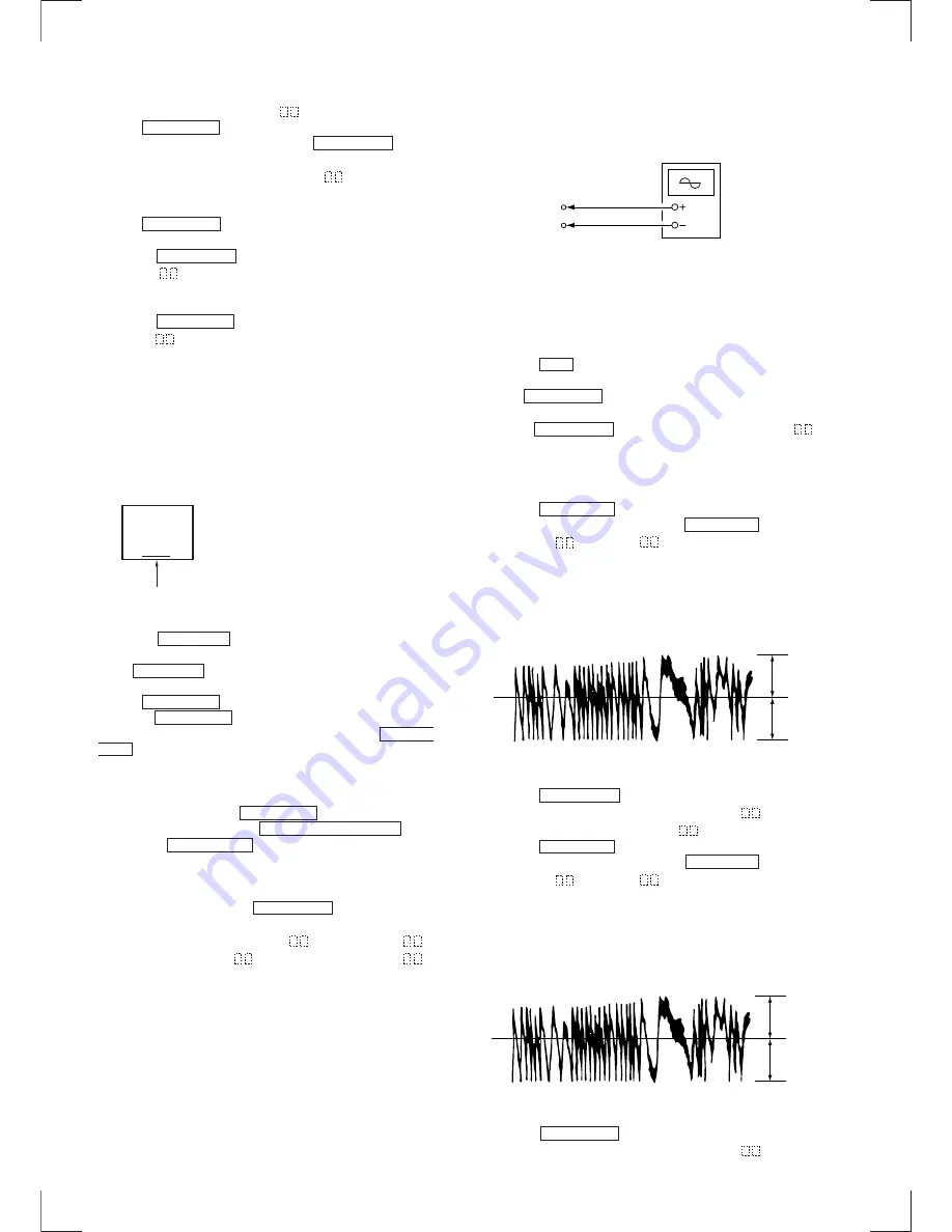
Traverse Adjustment
Connection :
Adjusting method :
1. Connect an oscilloscope to TP233 (TEO) and TP416 (VC) of
the BD board.
2. Insert an MO disc (any MO disc available on the market). (Refer
to Note 1.)
3. Press the
)
button and move the optical pickup toward
outer circumference of the pit area.
4. Rotate MULTI JOG and let the display “EF MO ADJUST”
(11) appear.
5. Press the ENTER/YES button and let the display “EFB =
MO-R” appear.
(The read laser power is turned on, the focus servo is turned
ON, the tracking servo is turned OFF and the spindle (S) servo
is turned ON.)
6. Rotate the MULTI JOG until the waveform on an oscilloscope
satisfies the specified value. (When the MULTI JOG is rotated,
the numbers
of “EFB =
” changes and the waveform
also changes.) The waveform changes at the step of approx. 2
% in this adjustment. Adjust the waveform until the waveform
becomes as closest as possible to the satisfied value.
(Read power traverse adjustment)
7. Press the ENTER/YES button to save the resultant data of
adjustment in the non-volatile memory. (“EFB =
SAVE” is
displayed for a moment. Then “EFB =
MO-W” is displayed.)
8. Rotate the MULTI JOG until the waveform on an oscilloscope
satisfies the specified value. (When the MULTI JOG is rotated,
the numbers
of “EFB =
” changes and the waveform
also changes.) The waveform changes at the step of approx. 2
% in this adjustment. Adjust the waveform until the waveform
becomes as closest as possible to the satisfied value.
(Write power traverse adjustment)
9. Press the ENTER/YES button to save the resultant data of
adjustment in the non-volatile memory. (“EFB =
SAVE” is
displayed for a moment.)
KMS
260A
27X40
B0825
(Label of optical pickup)
For the procedure to check this value,
refer to section “Recording and
Display of IOP Information”.
Iop = 82.5 mA in this example
Iop (mA) = Digital voltmeter reading (mV) / 1(
Ω
)
V : 0.5V/div H : 10ms/div
Input : DC mode
TP233 (TEO)
TP416 (VC)
BD board
Oscilloscope
VC
A
B
(Traverse Waveform)
Specification : A = B
VC
A
B
(Traverse Waveform)
Specification : A = B
Summary of Contents for HCD-MD555
Page 13: ... 13 This section is extracted from instruction manual ...
Page 14: ... 14 ...
Page 15: ... 15 ...
Page 16: ... 16 ...
Page 17: ... 17 ...
Page 18: ... 18 ...
Page 19: ... 19 ...
Page 20: ... 20 ...
Page 21: ... 21 ...
Page 22: ... 22 ...
Page 23: ... 23 ...
Page 24: ... 24 ...
Page 74: ...HCD MD555 95 96 7 20 SCHEMATIC DIAGRAM PANEL SECTION Refer to page 110 for IC Block Diagrams ...
Page 122: ... 148 MEMO HCD MD555 ...


