background image

 162 

KD-30XS955/34XBR960/34XS955/36XS955

KD-30XS955/34XBR960/34XS955/36XS955

         REF. NO.  

PART NO. 

DESCRIPTION 

 VALUES   

         REF. NO.  

PART NO. 

DESCRIPTION 

 VALUES   

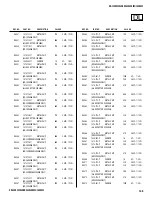
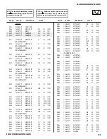
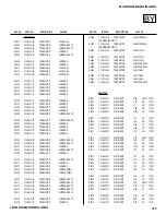
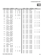
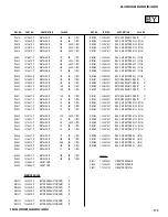
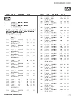
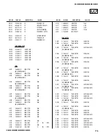
 C3351  1-164-156-11  CERAMIC 

CHIP 

0.1µF   25V 


 C3357  1-164-156-11  CERAMIC 

CHIP 

0.1µF   25V 


 C3358  1-164-156-11  CERAMIC 

CHIP 

0.1µF   25V 


 C3359  1-126-204-11  ELECT 

CHIP 

47µF  20% 

16V

 C3360  1-164-156-11  CERAMIC 

CHIP 

0.1µF   25V 


 C3363  1-126-204-11  ELECT 

CHIP 

47µF  20% 

16V

 C3364  1-164-156-11  CERAMIC 

CHIP 

0.1µF   25V 


 C3365  1-164-156-11  CERAMIC 

CHIP 

0.1µF   25V 


 C3366  1-164-156-11  CERAMIC 

CHIP 

0.1µF   25V 


 C3367  1-164-156-11  CERAMIC 

CHIP 

0.1µF   25V 


 C3368  1-164-156-11  CERAMIC 

CHIP 

0.1µF   25V 


 C3369  1-164-156-11  CERAMIC 

CHIP 

0.1µF   25V 


 C3370  1-164-156-11  CERAMIC 

CHIP 

0.1µF   25V 


 C3371  1-164-156-11  CERAMIC 

CHIP 

0.1µF   25V 


 C3372  1-164-156-11  CERAMIC 

CHIP 

0.1µF   25V 


 C3374  1-164-156-11  CERAMIC 

CHIP 

0.1µF   25V 


 C3375  1-127-760-11  CERAMIC 

CHIP 

4.7µF 10% 

6.3V

 C3376  1-164-156-11  CERAMIC 

CHIP 

0.1µF   25V 


 C3377  1-162-970-11  CERAMIC 

CHIP 

0.01µF 10% 

25V

 C3378  1-126-204-11  ELECT 

CHIP 

47µF  20% 

16V

 C3379  1-164-156-11  CERAMIC 

CHIP 

0.1µF   25V 


 C3401  1-164-156-11  CERAMIC 

CHIP 

0.1µF   25V 


 C3402  1-124-779-00  ELECT 

CHIP 

10µF  20% 

16V

 C3403  1-164-156-11  CERAMIC 

CHIP 

0.1µF   25V 


 C3404  1-126-206-11  ELECT 

CHIP 

100µF 20% 

6.3V

 C3405  1-126-206-11  ELECT 

CHIP 

100µF 20% 

6.3V

 C3406  1-107-826-11  CERAMIC 

CHIP 

0.1µF 10% 

16V

 C3407  1-107-826-11  CERAMIC 

CHIP 

0.1µF 10% 

16V

 C3408  1-126-206-11  ELECT 

CHIP 

100µF 20% 

6.3V

 C3409  1-164-156-11  CERAMIC 

CHIP 

0.1µF   25V 


 C3410  1-164-156-11  CERAMIC 

CHIP 

0.1µF   25V 


 C3411  1-164-156-11  CERAMIC 

CHIP 

0.1µF   25V 


 C3412  1-164-156-11  CERAMIC 

CHIP 

0.1µF   25V 


 C3413  1-164-156-11  CERAMIC 

CHIP 

0.1µF   25V 


 C3414  1-164-156-11  CERAMIC 

CHIP 

0.1µF   25V 


 C3417  1-164-156-11  CERAMIC 

CHIP 

0.1µF   25V 


 C3418  1-107-826-11  CERAMIC 

CHIP 

0.1µF 10% 

16V

 C3424  1-164-156-11  CERAMIC 

CHIP 

0.1µF   25V 


 C3426  1-164-156-11  CERAMIC 

CHIP 

0.1µF   25V 


 C3428  1-107-826-11  CERAMIC 

CHIP 

0.1µF 10% 

16V

 C3431  1-126-204-11  ELECT 

CHIP 

47µF  20% 

16V

 C3435  1-164-156-11  CERAMIC 

CHIP 

0.1µF   25V 


 C3436  1-107-826-11  CERAMIC 

CHIP 

0.1µF 10% 

16V

 C3439  1-164-156-11  CERAMIC 

CHIP 

0.1µF   25V 


 C3440  1-162-916-11  CERAMIC 

CHIP 

12pF  5% 50V

 C3441  1-162-916-11  CERAMIC 

CHIP 

12pF  5% 50V

 C3442  1-124-779-00  ELECT 

CHIP 

10µF  20% 

16V

 C3444  1-164-156-11  CERAMIC 

CHIP 

0.1µF   25V 


 C3446  1-107-826-11  CERAMIC 

CHIP 

0.1µF 10% 

16V

 C3449  1-107-826-11  CERAMIC 

CHIP 

0.1µF 10% 

16V

 C3450  1-164-156-11  CERAMIC 

CHIP 

0.1µF   25V 


 C3452  1-164-156-11  CERAMIC 

CHIP 

0.1µF   25V 


 C3460  1-162-923-11  CERAMIC 

CHIP 

47pF  5% 50V

 C3462  1-164-156-11  CERAMIC 

CHIP 

0.1µF   25V 


 C3463  1-164-156-11  CERAMIC 

CHIP 

0.1µF   25V 


 C3464  1-164-156-11  CERAMIC 

CHIP 

0.1µF   25V 


 C3465  1-164-156-11  CERAMIC 

CHIP 

0.1µF   25V 


 C3466  1-164-156-11  CERAMIC 

CHIP 

0.1µF   25V 


 C3467  1-164-156-11  CERAMIC 

CHIP 

0.1µF   25V 


 C3468  1-126-206-11  ELECT 

CHIP 

100µF 20% 

6.3V

 C3469  1-164-156-11  CERAMIC 

CHIP 

0.1µF   25V 


 C3470  1-126-206-11  ELECT 

CHIP 

100µF 20% 

6.3V

 C3473  1-164-156-11  CERAMIC 

CHIP 

0.1µF   25V 


 C3474  1-124-779-00  ELECT 

CHIP 

10µF  20% 

16V

 C3475  1-164-156-11  CERAMIC 

CHIP 

0.1µF   25V 


 C3476  1-124-779-00  ELECT 

CHIP 

10µF  20% 

16V

 C3477  1-164-156-11  CERAMIC 

CHIP 

0.1µF   25V 


 C3478  1-126-204-11  ELECT 

CHIP 

47µF  20% 

16V

 C3479  1-124-779-00  ELECT 

CHIP 

10µF  20% 

16V

 C3480  1-164-156-11  CERAMIC 

CHIP 

0.1µF   25V 


 C3481  1-117-681-11  ELECT 

CHIP 

100µF 20% 

16V

 C3482  1-117-681-11  ELECT 

CHIP 

100µF 20% 

16V

 C3483  1-117-681-11  ELECT 

CHIP 

100µF 20% 

16V

 C3484  1-125-837-91  CERAMIC 

CHIP 

1µF  10% 

6.3V

 C3485  1-164-156-11  CERAMIC 

CHIP 

0.1µF   25V 


 C3486  1-164-156-11  CERAMIC 

CHIP 

0.1µF   25V 


 C3487  1-164-156-11  CERAMIC 

CHIP 

0.1µF   25V 


 C3488  1-124-779-00  ELECT 

CHIP 

10µF  20% 

16V

 C3489  1-164-156-11  CERAMIC 

CHIP 

0.1µF   25V 


 C3490  1-124-779-00  ELECT 

CHIP 

10µF  20% 

16V

 C3491  1-126-204-11  ELECT 

CHIP 

47µF  20% 

16V

 C3492  1-164-156-11  CERAMIC 

CHIP 

0.1µF   25V 


 C3493  1-126-204-11  ELECT 

CHIP 

47µF  20% 

16V

 C3494  1-164-156-11  CERAMIC 

CHIP 

0.1µF   25V 


 C3495  1-124-779-00  ELECT 

CHIP 

10µF  20% 

16V

 C3496  1-164-156-11  CERAMIC 

CHIP 

0.1µF   25V 


 C3499  1-162-970-11  CERAMIC 

CHIP 

0.01µF 10% 

25V

 C3500  1-126-206-11  ELECT 

CHIP 

100µF 20% 

6.3V

BY

Summary of Contents for FD Trinitron WEGA Hi-Scan KD-34XS955

Page 1: ... A KD 34XBR960 RM Y201 HAWAII SCC S69L A KD 34XS955 RM Y199 US SCC S66W A KD 34XS955 RM Y199 CANADA SCC S70V A KD 34XS955 RM Y199 HAWAII SCC S69M A KD 36XS955 RM Y199 US SCC S66X A KD 36XS955 RM Y199 HAWAII SCC S69N A HISTORY INFORMATION FOR THE FOLLOWING MANUAL ORIGINAL MANUAL ISSUE DATE 6 2004 REVISION DATE REVISION TYPE SUBJECT 6 2004 No revisions or updates are applicable at this time 7 2004 R...

Page 2: ...C S66U A KD 30XS955 RM Y199 HAWAII SCC S69K A KD 34XBR960 RM Y201 US SCC S66V A KD 34XBR960 RM Y201 HAWAII SCC S69L A KD 34XS955 RM Y199 US SCC S66W A KD 34XS955 RM Y199 CANADA SCC S70V A KD 34XS955 RM Y199 HAWAII SCC S69M A KD 36XS955 RM Y199 US SCC S66X A KD 36XS955 RM Y199 HAWAII SCC S69N A SelfDiagnosis Supported model KD 34XBR960 RM 201 ...

Page 3: ... 48 4 1 1 Service Adjustment Mode In 48 4 1 2 Service Adjustment Mode Memory 48 4 1 3 Reading the Memory 48 4 1 4 Adjusting the Picture 48 4 1 5 Resetting the Data 48 4 1 6 Resetting the MID NVM Data 48 4 1 7 Resetting the System NVM Data 48 4 1 8 Copy Function 48 4 2 Memory Write Confirmation Method 49 4 3 Remote Adjustment Buttons and Indicators 49 4 4 Service Data 50 KD 34XBR960 Service Data On...

Page 4: ... In CableCARD Standby 20 W 23 W 20 W 20 W Dimensions W x H x D mm 898 x 604 x 564 5 mm 994 x 652 x 605 mm 994 x 654 x 604 mm 994 x 776 5 x 634 mm in 35 3 8 x 23 3 4 x 22 1 4 in 39 1 8 x 25 5 8 x 23 7 8 in 39 1 8 x 25 3 4 x 23 3 4 in 39 1 8 x 30 5 8 x 25 in Mass kg 67 kg 89 kg 93 kg 108 2 kg lbs 148 lbs 196 lbs 205 lbs 238 5 lbs 7 5 W x 2 15W Subwoofer SRS SOUND RETRIEVAL SYSTEM The SRS SOUND RETRI...

Page 5: ...measured diagonally KD 36XS955 Only Actual screen size 32 inch measured diagonally KD 30XS955 Only 36 inch measured diagonally KD 34XBR960 34XS955 Only 38 inch measured diagonally KD 36XS955 Only Antenna 75 ohm external terminal for VHF UHF Supplied Accessories Remote Commander RM Y199 KD 30XS955 34XS955 36XS955 Only RM Y201 KD 34XBR960 Only Two Size AA R6 Batteries Optional Accessories AV Cable V...

Page 6: ...s suspected ATTENTION Apres avoir deconnecte le cap de l anode court circuiter l anode du tube cathodique et celui de l anode du cap au chassis metallique de l appareil ou la couche de carbone peinte sur le tube cathodique ou au blindage du tube cathodique Afin d eviter tout risque d electrocution provenant d un chássis sous tension un transformateur d isolement doit etre utilisé lors de tout dépa...

Page 7: ... metal parts to any exposed metal part having a return to chassis must not exceed 0 5 mA 500 microamperes Leakage current can be measured by any one of three methods 1 A commercial leakage tester such as the Simpson 229 or RCA WT 540A Follow the manufacturers instructions to use these instructions 2 A battery operated AC milliampmeter The Data Precision 245 digital multimeter is suitable for this ...

Page 8: ...of times STANDBY TIMER lamp flashes Display Result Probable Cause Location Detected Symptoms Power does not turn on Does not light _______ Power cord is not plugged in Fuse is burned out F501 AZ Board Power does not come on No power is supplied to the TV AC Power supply is faulty B Overcurrent OCP 2 times 2 0 or 2 1 H OUT Q5030 is shorted DZ Board B PWM Q5003 is shorted DZ Board Power does not com...

Page 9: ...detect subsequent faults after completion of the repairs Clearing the Result Display To clear the result display to 0 press buttons on the Remote Commander sequentially when the diagnostic screen is displayed as shown below NOTE This will also reset all user functions including auto programming and picture settings ENTER Channel 8 Quitting the Self Diagnostic Screen To quit the entire self diagnos...

Page 10: ...STOP Occurs when an absence of the vertical deflection pulse is detected by pin 24 of IC2801 BY Board Power supply will shut down when waveform interval exceeds 2 seconds White Balance Failure If the RGB levels do not balance within 2 seconds after the power is turned on this error will be detected by IC2801 TV will stay on but there will be no picture Refers to the RGB levels of the AKB detection...

Page 11: ...8018 VpK 250V is 15V Do not touch or short to GND or any other components CAUTION Pay attention to Neck Assembly WY Board wire harness to BY Board The WY Board can easily break if there is sudden or excessive tension on the harness 1 Lift lever up on the right and left sides of the chassis bracket and gently pull the chassis assembly away from the bezel 2 Pull up and rotate both the AZ and DZ Boar...

Page 12: ...om the anode button the anode cap can be removed by turning the rubber cap and pulling it in the direction of arrow c HOW TO HANDLE AN ANODE CAP 1 Do not use sharp objects which may cause damage to the surface of the anode cap 2 To avoid damaging the anode cap do not squeeze the rubber covering too hard A material fitting called a shatter hook terminal is built into the rubber 3 Do not force turn ...

Page 13: ...ole DY leads are dressed in ADHESIVE STRIPS Place OVER ECG ECG MUST touch CRT in this area E C G E C G Leads DGC purselock to hold DY Leads DY Rotation COIL Cable Tie To CN504 505 on A Board LCC Coil Top LCC Coil Top Rev 1 6 28 04 Cable Tie CN5805 DL LCC Coil Bottom LCC Coil Bottom NOTE MAKE SURE Cable Tie is positioned so it does NOT touch LCC COIL Wires DO NOT apply Cable Tie over white black LC...

Page 14: ...09 G2 REV 1 6 28 04 CN9004 ECG CLP9003 Dress wires with ONE LOOP in Clamp SIDE VIEW CX WY CRT SOCKET B Side CN9002 CN9002 Dress Wire in Clamp With ONE Loop The Loop Will take the Stress off the Connector Header CN9002 3WIRE 4p Conn Assy p n 1 900 807 06 200V LEAD WIRE DRESSING CAUTION POINT ALL MODELS ...

Page 15: ...0 34XS955 36XS955 This was a defect from Pre Pro set Important to check alignment of POD Eject Buttom VERY important if QBOX is replaced in the field POD EJECT BUTTON CAUTIONS ALIGNMENT CHECK ALL MODELS POD EJECT BUTTON CAUTIONS NG BUTTON POSITION ALL MODELS ...

Page 16: ...16 KD 30XS955 34XBR960 34XS955 36XS955 KD 30XS955 34XBR960 34XS955 36XS955 POD EJECT BUTTON CAUTIONS STEP 1 BEFORE INSERT CARD ALL MODELS POD EJECT BUTTON CAUTIONS STEP 2 INSERT CARD ALL MODELS ...

Page 17: ...IEW FBT U Bracket Wire Holder p n 4 065 850 11 N G CONDITION SIDE VIEW FBT U Bracket G2 WIRE 1 900 808 42 FBT REAR VIEW Dress wire in L Shape N G Wire can touch Rear Cover G2 Wire MUST be routed correctly so that the wire does NOT touch Rear Cover Causes Buzzing sound Route wire in front of U Bracket REV 1 5 03 04 Wire Holder p n 4 065 850 11 ...

Page 18: ... Arm Supporter Woofer Arm Supporter SIDE VIEW Woofer Arm Woofer Arm N G Condition O K Condition Touch N G WOOFER ARM WIRE DRESSING CAUTION KD 34XBR960 ONLY Rev 1 6 28 04 4 079 129 21 50 x 20mm Himelon Tape Align with edge of Pierce D Cut Out on HS BAND HS BAND FRONT PANEL Bottom of 16X9 CRT D Cut Out D Cut Out FRIT LINE ALIGN TAPE WITH EDGE OF D CUT OUT TOLERANCE 5mm ALIGN TAPE WITH EDGE OF D CUT ...

Page 19: ...s secure on CRT pierce Caution Make sure hook is secure on CRT pierce Caution Make sure hook is secure on CRT pierce Wrap 2 TIMES for 34W CHECK for NO SLACK ON WIRE Caution Make sure Cable Tie is TIGHTENED once CRT is in Vertical postion Caution Make sure Cable Tie is TIGHTENED once CRT is in Vertical postion DY Rotation COIL Rev 1 6 28 04 CRT BRKT WIRE HOOK 4 097 355 01 NOTE Leads are dressed ins...

Page 20: ...C Coil LCC Coil CRT Ground Wire 34XBR 1 900 808 04 DGC Tension Cable p n 1 900 803 55 2 Loops for 34XBR DGC DGC REV 1 6 28 04 OK INSTALLATION w Countermeasure Himelon Tape p n 4 079 129 21 Center Tape over the END of the tension spring Himelon Tape p n 4 079 129 21 Center Tape over the END of the tension spring Rev 1 6 28 04 CRT BRKT X2 p n 4 093 523 XX 34XBR North South Coil N S 1 424 695 11 34XB...

Page 21: ... 4 079 129 21 2 PLACES Make sure tweeter terminals are facing AWAY from CRT CLAMP P N 4 857 472 01 4X16mm Screw p n 7 685 663 99 TORQUE 12kg cm 1 Hold Capacitor down with Himelon tape to prevent vibration and touching CRT Make sure Tweeter leads do NOT touch Beznet Rib dashed line Wires can Pinch when Rear Cover is installed SPEAKER ASSY WIRE DRESSING LEFT SPEAKERS KD 34XBR960 ONLY ...

Page 22: ... p n 7 685 663 99 TORQUE 12kg cm 1 Make sure tweeter terminals are facing AWAY from CRT Hold Capacitor down with Himelon tape to prevent vibration and touching CRT Make sure Tweeter leads do NOT touch Beznet Rib dashed line Wires can Pinch when Rear Cover is installed WOOFER ASSY WIRE DRESSING KD 34XBR960 ONLY CRT Bracket A To FBT CRT Bracket Cable Tie Rev 1 6 28 04 DY ANODE LEAD Bundle slack in P...

Page 23: ... Double Ground Wire w ferrite core p n 1 500 082 11 NOTE Tab on AZ Bd CN 519 is bent over in 45degree angle USB Cable p n 1 829 191 11 black cable routed in H Bracket clips iLINK Cable 1 823 515 31 w I Holder plastic clip on HBZ Bd p n 4 082 405 01 1 900 805 24 dressed in H bracket clips USB CABLE dressed in H Bracket clips NOTE Mounted tab on QH board is bent 45degrees NOTE Over Molded Ferrite Po...

Page 24: ...to DL BD p n 1 900 808 32 6P Conn Assy BY Bd to WY BD 11P Conn Assy w Yellow Taping p n 1 900 806 86 routed to CX Bd This end of 1 900 806 86 connects to CX Bd NOTE This Conn Assy Is routed INSIDE the 9mm black purselock NOTE KNOT is only for picture DO NOT knot wires during actual dressing NOTE 1 900 808 32 6P Conn Assy Is routed INSIDE clamp p n 4 857 472 01 WIRE DRESSING QBOX DRESSING KD 34XBR9...

Page 25: ... far BACK as possible EMI Reasons 11mm purselock p n 3 703 983 02 Qty 4 iLINK cable NOT dressed in this purselock Main bundle dressed low as possible EMI Reasons DO NOT let wires touch Cement Resistor or heat sink WIRE DRESSING FERRITE ADDITIONS KD 34XBR960 ONLY LOCATIONS OF FERRITE CORES EFFECT EMI PERFORMANCE Please use caution when positioning ferrite cores ...

Page 26: ...ion of purselocks and postion of ferrite cores Ferrite Core NOTE LOCATION IMPORTANT for EMI Ferrite Core NOTE LOCATION IMPORTANT for EMI p n 1 500 484 21 p n 1 543 793 11 TDK ZCAT 2017 0930 M TDK ZCAT 1325 0530A 1 900 805 24 ground wire is dressed in wire clamp p n 4 857 472 01 Wire is dressed BEFORE securing position of Antenna Switch WIRE DRESSING ANT SW GROUND WIRE KD 34XBR960 ONLY ...

Page 27: ...Note position rotation of right angle connector of the cable ferrite Do NOT dress the ferrite core so it can touch the Heat sink on the POD connector not installed in this photo NOTE Z Routing of USB Cable routing important for EMI Position of Ferrite Core is Important for EMI WIRE DRESSING FRONT OF Q BOX KD 34XBR960 ONLY ...

Page 28: ...28 KD 30XS955 34XBR960 34XS955 36XS955 KD 30XS955 34XBR960 34XS955 36XS955 WIRE DRESSING 11MM P BOARD CONNECTION KD 34XBR960 ONLY ...

Page 29: ...E DRESSING ALL EXCEPT KD 34XBR960 DY Rev 1 5 10 04 Cable Tie 4 041 041 02 STEP1 Make a loop in leads and route loop BEHIND The DGC Coil STEP 2 Thread both connector housings through the loop in lead wires STEP 3 Plug in connector housings into the AZ Board using the loop to take up slack ...

Page 30: ... CRT is in Vertical postion Caution Make sure Cable Tie is TIGHTENED once CRT is in Vertical postion 2 022 978 01 Wire Clip 2 Places 1 900 803 55 DGC Restraint Cable 1 910 000 13 DGC Restraint Cable DGC ASSEMBLY CAUTION POINT KD 30XS955 34SX955 ONLY DY Rotation COIL Rev 1 7 12 04 CRT BRKT NOTE Leads are dressed inside Rotation Coil NOTE2 There are 2 Leads TOTAL 4 Wires to connect to CX Board ECG P...

Page 31: ...p n 1 900 808 41 with 9mm purselock p n 3 703 982 02 NOTE direction of wires in purselock CRITICAL POINT 14P Conn Assy P shield to MZ Bd p n 1 900 808 41 Note Direction of wires dressed in MUST be dressed as far back in the chassis as possible 11mm purselock p n 3 703 983 02 NOTE position of the ferrite core adjacent to P shield CHASSIS WIRE DRESSING DETAIL ALL EXCEPT KV 34XBR960 ...

Page 32: ...NT Main cable bundle MUST be dressed as LOW as possible between cement resistor and heat sink Wires cannot touch heat sink sharp edges or the cement resistor very hot CHASSIS WIRE DRESSING DETAIL ALL EXCEPT KV 34XBR960 XS Models do NOT have Sub Tuner Pin Plug Cable XS Models do NOT have iLINK iEEE Cable CHASSIS WIRE DRESSING DETAIL ALL EXCEPT KV 34XBR960 ...

Page 33: ...assis into set CHASSIS WIRE DRESSING DETAIL ALL EXCEPT KV 34XBR960 UZ Bd to HBZ Bd Conn Assy with Red taping p n 1 900 806 83 Dressed in purselock on MZ Bd p n 4 355 912 xx 4P WY Bd to DL Bd Conn Assy with Red Housing p n 1 900 808 02 Both 1 900 806 83 and 1 900 808 02 dressed in 9mm purselock p n 3 703 982 02 Both 1 900 806 83 and 1 900 808 02 dressed in H Bracket Clip NOTE Directions of cables I...

Page 34: ...1 RUMB 31 RLBW 31 RLMB 31 LSAP 31 LUBW 31 LUMB 31 LLBW 31 LLMB 31 CADJ 29 HVCA 31 CXA2170 D1 D2 table default initial data VCEN 24 VPIN 24 HTPZ 7 HCNT 31 PPHA 20 VANG 31 VBOW 31 LBOW 31 LANG 31 NOTE Do not use the hand degausser it magnetizes the CRT 1 Input white pattern from pattern generator Set the PICTURE control to maximum and the BRIGHTNESS control to standard 2 Loosen the deflection yoke m...

Page 35: ...CX Board to converge red green and blue dots in the center of the screen 3 Adjust V STAT magnet to converge red green and blue dots in the center of the screen R G B Center dot RV9001 H STAT V STAT magnet R G B 4 Tilt the V STAT magnet and adjust static convergence to open or close the V STAT magnet B G R B G R 1 2 3 2 OPERATION OF BMC HEXAPOLE MAGNET The respective dot positions result from movin...

Page 36: ...namic convergence using the following service registers Note areas of change Only H component can be corrected for vertical component use permalloy to compensate 0 YBWU Upper Y BOW B R B R 1 YBWL Lower Y BOW B R B R 2 RSAP Right H AMP R B 3 RUBW Right Upper BOW B R 4 RUMB Right Upper Middle BOW B R 5 RLBW Right Lower BOW R B 6 RLMB Right Lower Middle BOW B R 7 LSAP Left H AMP B R 8 LUBW Left Upper...

Page 37: ... the data to the vertical compressed modes Note V compressed data is identical to non v compressed data Service personnel with a trained eye can adjust the DF or DQP registers to adjust DF phase Item 7 or DQP phase Item 8 respectively to balance left and right focus Refrain from adjusting more than 5 steps from table data below Further adjustment indicates a circuit problem troubleshoot to cause C...

Page 38: ...pe to Pin 1 of CN9001 R DRV on the CX Board 3 Adjust contrast according to the service mode item SPIO NO Name Control Function 02 SCON SUB CONT 2103 1 white black GND VR2 VR1 VR 32XS 34XBR 34XS 36XS 1 60 0 05 Vpp 4 Write data from Step 3 above into memory 2 6 PICTURE QUALITY ADJUSTMENTS Preparation Set PRO MODE Reset 1 Input signal 480i Composite Color Bar Video 75 IRE White 75 modulation 7 5 Set ...

Page 39: ...de for SHUO NO Name Control Function 03 SCOL SUB COL 04 SHUE SUB HUE 2103 1 VB4 VB3 VB2 VB1 COLOR VB1 VB4 20mV 200 mV HUE VB2 VB3 20mV 200 mV 5 Write data into memory 2 6 3 RF INPUT SUB CONTRAST ADJUSTMENT Preparation Input a Color Bar signal to RF 75 IRE 75 Set picture mode Single Full PRO MODE Picture Max Color Min 1 Set to Service Mode and adjust as follows NO Name Control Function Avg Data 01 ...

Page 40: ...d 3 Adjust color according to Service Mode for SCOL 4 Adjust color according to Service Mode for SHUE NO Name Control Function 03 SCOL SUB COLOR 04 SHUE SUB HUE 2103 1 VB4 VB3 VB2 VB1 COLOR VB1 VB4 20mV 200 mV HUE VB2 VB3 20mV 200 mV 5 Write data into memory 2170P 4 2 7 WHITE BALANCE CRT AND SUB BRIGHT ADJUSTMENT Preparation Input an all white 480I 15 734 KHz signal into the VIDEO 1 input terminal...

Page 41: ...rol Function 3 CBOF CB0F FROM VIDEO 5 3 4 CROF CR0F FROM VIDEO 5 4 2 8 H RASTER CENTER ADJUSTMENT Preparation Input a monoscope signal Set to NTSC DRC mode 1 Set to Service Mode and adjust as follows NO Name Control Function Data 05 AGNG AGING 1 AGING 2 2 NO Name Control Function Avg Data 02 HSIZ Horiz Size 31 01 HPOS Horiz Position 31 NO Name Control Function Avg Data 00 HBLK Blanking Enable 0 CX...

Page 42: ...t VSIZ and VPOS and write the data 7 Adjust for Vertical line distortion 8 Adjust VANG VBOW LANG LBOW Note Keep LANG and LBOW data between 5 and 58 9 Finish with UCP LCP PPHA PIN adjustments 10 Check SLIN MPIN Adjust for correct HSIZ and HPOS and write the data before changing modes NOTE Make sure that the picture size is within specs Vertical size is 11 8 0 1 sq and horizontal size is 15 8 0 1 sq...

Page 43: ...correct upper lower horizontal line straightness Adjust other registers in Full mode above as necessary being careful to balance any shared data effect between modes 5 Repeat steps 3 and 4 for IDSW set to 3 VC 1080i 6 Write the data before changing modes 2 9 4 NORMAL ZOOM AND WIDE ZOOM MODES 1 Check Normal and Zoom modes for size and position 2 Optimize VPIN adjustment in Normal mode for the strai...

Page 44: ...DZ board screws and carefully lift board as necessary to gain access to the bottom of the board 2 Unsolder CN5001 pin 1 to open ABL connection to AZ board Alternately open AZ DZ connector CN509 CN5001 and carefully push pin 1 metal tab ABL up from the bottom and pull up from the top using long nose pliers and release it from the connector then close the connector with pin 1 connection now open 3 I...

Page 45: ...015 2 Set ABL current to 2 76mA by adjusting picture and brightness towards max condition 3 Confirm that AC Relay shuts off 4 Remove short from C8015 and Short across C8012 5 Turn the set off and on to reset AC relay latch 6 Confirm the voltage at CN5009 pin 8 H_prot 3 6 0 5V 7 Remove short from C8012 3 8 HOLD DOWN CHECK 1 Using an external DC power supply apply 5 3 0 5 Vdc between Pin 2 of CN507 ...

Page 46: ...e part on P 47 changed Is DZ Board changed NO Start Which category part on P 47 changed NO YES Finished with HV service Confirm HV HV Protector Ik Protector Refer to P 44 45 Confirm HV Protector Refer to P 44 45 Confirm B Refer to P 44 Confirm HV Refer to P 44 45 Confirm B Hold Down Refer to P 44 Category A Category B Category C Category D Category E ...

Page 47: ...R8035 E R8036 E R8037 E R8038 E R8039 E R8040 E R8043 E R8078 D R8165 D IC8005 C IC8104 D R8012 C R8014 C R8016 D R8021 C R8027 E R8029 E R8030 E R8031 E R8046 D R8052 D R8059 C R8060 C R8066 C R8072 D R8079 D R8082 E R6590 B D8022 D PH8003 C Q8007 E Q8008 E IC8001 D IC8002 C IC8004 C IC6503 B HS SERVICE FLOWCHART TABLE ...

Page 48: ...3 Digital multimeter 4 Audio oscillator 4 1 3 READING THE MEMORY 1 Enter into Service Mode 2 Press 0 on the Remote Commander 3 Press ENTER to read memory 4 1 4 ADJUSTING THE PICTURE 1 Enter into Service Mode 2 Press 2 or 5 on the remote to select the device item 3 Press 1 or 4 on the remote to select an item 4 Press 3 or 6 on the remote to change the data 5 Press MUTING then ENTER to write into me...

Page 49: ...C outlet again 2 Turn the power switch ON and set to Service Mode 3 Call the adjusted items again to confirm they were adjusted 4 3 REMOTE ADJUSTMENT BUTTONS AND INDICATORS RM Y201 Enter into memory MUTING POWER Service Mode Disp Item Up 1 Device Item up 2 Disp Item Down 4 Initialize 8 VOLUME Service Mode 3 Item Data Up 6 Item Data Down 5 Device Item Down Remove from Memory 0 DISPLAY Service Mode ...

Page 50: ...A 0 15 10 10 10 10 10 DCCO 0 15 5 5 5 5 11 DCGA 0 15 5 5 5 5 12 WSC 0 2 1 13 WSS 0 1 0 Vivid Standard Movie Pro 14 VAPG 0 7 4 2 2 0 15 VAPI 0 31 4 4 4 0 16 TEST 0 1 0 RF CV YC RF CV YC RF CV YC RF CV YC 17 YPFT 0 3 3 3 3 3 3 3 3 3 3 18 YPFG 0 15 9 6 7 5 5 6 5 5 6 19 SEDC 0 1 0 20 SEDY 0 1 1 21 YHCO 0 3 1 22 YHCG 0 1 0 23 SYSP 0 3 0 24 TES2 0 7 0 Standard Vivid Note Item uses the fixed setting in n...

Page 51: ...C 6 SHAP 0 15 9 8 4 4 8 7 SHF0 0 3 0 0 3 3 0 8 PRE0 0 3 3 3 3 3 3 9 BPF0 0 3 3 10 BPFQ 0 3 2 RF CV YC 11 BPSW 0 1 1 0 12 TRAP 0 1 0 13 LPF 0 1 1 RF CV YC Others 14 AFCG 0 1 1 0 0 15 CDMD 0 3 3 3 3 16 SSMD 0 3 0 0 0 RF CV YC V5 V6 HDMI ATSC 17 HMSK 0 1 0 1 1 1 0 18 HALI 0 1 0 RF CV YC V5 V6 HDMI ATSC 19 PPHA 0 15 7 7 7 7 7 V5 V6 ATSC Others 20 CBO1 0 63 31 31 31 21 CRO1 0 63 31 31 31 HDMI ATSC 22 C...

Page 52: ...t F A 2103 2 DRC VDO 0 YLEV 0 63 24 41 1 CLEV 0 63 10 31 RF CV YC 2 SCON 0 15 8 6 3 SCOL 0 15 7 7 4 SHUE 0 15 7 9 5 YDLY 0 3 0 0 6 SHAP 0 15 6 8 7 SHF0 0 3 0 0 8 PREO 0 3 3 3 9 BPF0 0 3 3 10 BPFQ 0 3 0 RF CV YC 11 BPSW 0 1 1 0 12 TRAP 0 1 0 DRC VDO 13 LPF 0 1 1 0 RF CV YC 14 AFCG 0 1 1 0 15 CDMD 0 3 3 3 16 SSMD 0 3 0 0 17 HMSK 0 1 0 1 18 HALI 0 1 0 RF CV YC 19 PPHA 0 15 7 7 20 CBO1 0 63 37 21 CRO1...

Page 53: ... 46 45 31 41 46 47 31 42 47 47 1080i PT 5 CBOP 0 63 36 6 CROP 0 63 37 Offset from V5 V6 480i s data Color Temp Neutral 7 SBRT 0 63 24 8 RDRV 0 63 32 9 GDRV 0 63 22 10 BDRV 0 63 20 11 RCUT 0 63 32 12 GCUT 0 63 16 13 BCUT 0 63 22 Cool Warm 14 WBSW 0 1 0 0 15 SBOF 0 15 7 7 16 RDOF 0 63 31 31 17 GDOF 0 63 31 26 18 BDOF 0 63 34 16 19 RCOF 0 63 31 31 20 GCOF 0 63 31 27 21 BCOF 0 63 34 19 22 DCOL 0 3 1 0...

Page 54: ... 1 0 1 0 1 0 0 1 0 1 1 1 0 1 0 12 CTLV 0 3 0 0 0 0 3 3 0 0 0 3 3 3 0 0 0 3 3 13 UBOF 0 7 0 0 1 0 0 0 1 1 1 1 1 1 1 1 1 1 1 14 UCOF 0 7 2 2 2 2 2 2 2 2 2 2 2 2 2 2 2 2 2 15 UHOF 0 3 0 0 0 0 0 0 0 0 0 0 0 0 0 0 0 0 0 16 MIDE 0 63 7 11 15 19 23 27 15 19 19 23 27 23 56 15 19 23 27 RF CV YC 480i 480p 1080i 720p 480i 480p VGA 1080i 720p 480i 480p 1080i 720p 0 SYSM 0 3 1 1 1 2 3 3 1 2 2 3 3 3 2 1 2 3 3 1...

Page 55: ... 0 0 0 0 0 0 0 0 0 0 0 0 0 0 16 MIDE 0 63 3 9 13 17 21 25 13 17 17 21 25 21 54 13 17 21 25 RF CV YC 480i 480p 1080i 720p 480i 480p VGA 1080i 720p 480i 480p 1080i 720p 0 SYSM 0 3 1 1 2 2 3 3 2 2 2 3 3 3 2 2 2 3 3 1 VMLV 0 15 7 2 VMCR 0 3 1 0 0 0 0 0 0 0 0 0 0 0 3 0 0 0 0 3 VMLM 0 3 3 3 3 3 3 3 3 3 3 3 3 3 3 3 3 3 3 4 VMF0 0 3 1 1 0 0 0 0 0 0 0 0 0 0 0 0 0 0 0 5 VMDL 0 15 5 5 7 7 15 15 7 7 7 15 15 1...

Page 56: ...A 1080i 720p 480i 480p 1080i 720p Vivid 3 3 3 3 3 3 2 3 3 3 3 3 3 3 3 3 3 Standard 1 1 1 2 1 2 1 1 2 1 1 1 2 1 1 1 1 Movie 0 0 0 0 0 0 0 0 0 0 0 0 0 0 0 3 0 Pro 0 0 0 0 0 0 0 0 0 0 0 0 0 0 0 0 0 GAMM 0 GAMM 1 GAMM 2 GAMM 3 18 GAMS 0 15 0 8 8 8 19 GAMR 0 15 0 4 6 12 20 GAMG 0 15 0 4 6 12 21 GAMB 0 15 0 4 6 12 RF CV YC 480i 480p 1080i 720p 480i 480p VGA 1080i 720p 480i 480p 1080i 720p Vivid 3 3 3 3 ...

Page 57: ... 1 GAIN 0 3 0 0 0 V5 480p 720p 1080i No Sync V6 480p 720p 1080i No Sync HDMI 480p 720p 1080i No Sync ATSC 720p 1080i ATSC 480p MS Others 2 FIXS 0 3 3 3 3 2 3 1 PT Others HDMI 3 CBGN 0 15 8 5 3 4 CRGN 0 15 8 4 3 5 YGN 0 15 8 4 3 V5 V6 1080i MS HDMI 1080i Other 6 VTC 0 3 0 0 0 Tristate 1 Tristate 0 7 HTC 0 1 0 1 V5 V6 1080i MS HDMI 1080i Other 8 HWID 0 3 1 1 1 9 HSEP 0 1 1 1 1 V5 6 DVI MS 1080i Othe...

Page 58: ... TRS1 0 7 4 20 TRS2 0 7 2 SNNR 0 MODE 0 3 0 1 SNNR 0 7 0 WSLT A WSLT B WSLT C WSLT D WSLT E WSLT F WSLT G 2 WSLT 0 255 15 31 45 63 85 110 127 SNNR 0 SNNR 1 SNNR 2 SNNR 3 SNNR 4 SNNR 5 SNNR 6 SNNR 7 3 CPFG 0 15 0 0 1 1 2 2 2 3 4 CPFT 0 3 0 0 0 0 0 0 0 0 5 CCOR 0 3 0 0 1 1 1 1 1 1 6 CHCG 0 1 0 1 1 1 1 1 1 1 7 CAPG 0 7 0 0 0 0 0 0 0 0 8 3SHP 0 15 0 0 1 1 2 2 2 3 9 NYNR 0 15 0 1 2 2 3 3 4 4 10 NCNR 0 ...

Page 59: ...T 0 1 0 16 MESH 0 1 0 17 BNBB 0 3 1 18 BNBG 0 3 1 19 BNBR 0 3 0 20 CMP1 0 7 2 21 CMP2 0 7 5 22 CMP3 0 7 3 23 CWHT 0 7 3 24 VSDW 0 1 1 25 BFRQ 0 1 0 26 BPOS 0 1 0 27 BFRM 0 1 1 28 BTIM 0 1 0 3DNR 0 WHCT 0 63 44 1 NIQM 0 1 1 2 CLPW 0 63 30 3 CLPP 0 255 80 4 YHBW 0 255 138 5 YBKL 0 15 0 6 YBKO 0 1 0 7 MUTE 0 1 0 8 YHBS 0 127 40 9 CHBW 0 255 138 10 CBKO 0 127 40 11 CHBO 0 1 0 12 VHBL 0 15 0 13 UHBL 0 ...

Page 60: ... 0 1 0 480i Others 480i Others 480i Others 480i Others 43 YEL 0 15 6 4 6 6 6 6 6 6 44 YLM 0 127 6 6 6 6 6 6 6 6 45 CLV 0 15 15 15 10 10 10 10 8 8 46 CNT 0 1 1 47 CPL 0 1 1 480i Others 480i Others 480i Others 480i Others 48 CMG 0 3 3 3 3 3 3 3 3 3 49 CCR 0 31 3 3 3 3 3 3 3 3 50 CLM 0 127 6 6 6 6 6 6 6 6 51 NVSL 0 255 20 52 NVSH 0 1 1 53 NHS 0 127 16 54 NVEL 0 255 244 55 NVEH 0 1 0 56 NHE 0 127 120 ...

Page 61: ...Custom 2 Custom 3 4 AINI 0 127 0 49 79 5 BINI 0 127 24 54 89 6 FMAT 0 1 0 RF Others 7 FMTH 0 3 1 1 8 FSEL 0 1 1 9 CDLY 0 3 2 10 LMIT 0 1 0 Vivid Standard Movie Pro 11 LMLV 0 3 2 2 2 2 12 LMSL 0 1 1 13 VDLY 0 3 1 14 VDPR 0 3 3 15 WPLL 0 3 2 16 CRCT 0 1 0 SNNR 1 SNNR 2 SNNR 3 SNNR 4 SNNR 5 SNNR 6 SNNR 7 17 NRA 0 255 0 0 0 0 0 0 0 18 NRB 0 255 128 128 128 128 128 128 128 No service list only NVM data...

Page 62: ...omp 480Vcomp 12 APSW 0 1 1 1 1 0 0 1 13 ASPT 0 63 22 43 3 0 47 3 14 SCRL 0 63 31 31 31 31 31 31 WideZoom Others 15 UVLN 0 15 4 0 16 LVLN 0 15 4 0 2170D 2 0 HCNT 0 63 31 1080Full 1080Vcomp Others 1 HPOS 0 63 29 31 WideZoom Others 2 HSIZ 0 63 56 50 3 SLIN 0 15 10 4 4 MPIN 0 15 11 10 WideZoom Others 1080i 5 PIN 0 63 18 12 12 1080Vcomp WideZoom Zoom 480Full 1080Full 480Vcomp 6 PINO 0 15 7 7 7 9 7 Wide...

Page 63: ...0Vcomp 480Vcomp 4 TBLK 0 15 12 7 2 4 10 2 5 BBLK 0 15 15 7 8 6 13 8 1080Full 1080Vcomp Others 6 AFCM 0 3 2 3 1080Vcomp 480Vcomp 7 JUMP 0 1 0 480Vcomp 480Full 8 VDJP 0 1 1 1 0 1 1 1080Vcomp 1080Full Others 9 VDST 0 1 0 0 480Vcomp 480Full 10 AKBT 0 31 15 15 20 16 16 1080Vcomp 1080Vcomp 1080Full Zoom Note Data variation for 16x9 4x3 models Note Data variation for 16x9 4x3 models 1080Full Expansion Zo...

Page 64: ... 4 HFRQ 0 255 80 5 HFRX 0 63 25 6 VMPS 0 1 0 7 INTR 0 1 0 8 VLNL 0 3 0 9 VLNH 0 255 0 10 AGCS 0 1 0 D CONV 0 YBWU 0 63 31 CXA8070 1 YBWL 0 63 31 2 RSAP 0 63 31 3 RUMB 0 63 31 4 RUBW 0 63 31 5 RLMB 0 63 31 6 RLBW 0 63 31 7 LSAP 0 63 31 8 LUMB 0 63 31 9 LUBW 0 63 31 10 LLMB 0 63 31 11 LLBW 0 63 31 12 CADJ 0 63 23 13 HVCA 0 63 63 14 SRSP 0 63 63 15 SRUM 0 63 31 16 SRUB 0 63 63 17 SRLM 0 63 31 18 SRLB...

Page 65: ... 2 RT 0 255 127 3 RB 0 255 127 4 EWSP 0 15 5 5 ENSW 0 1 0 6 TESW 0 1 0 7 DHMT 0 1 0 8 LDVM 0 3 0 9 LVSW 0 1 0 10 LVPH 0 255 127 Wide Zoom Others Wide Zoom Others Wide Zoom Others Wide Zoom Others 11 HSZO 0 15 0 0 0 0 0 2 0 2 12 SLINO 0 15 0 0 0 0 0 1 0 1 13 MPNO 0 15 0 0 0 2 0 5 0 9 14 PINO 0 15 0 0 0 2 0 6 0 9 LDVM 2 LDVM 3 Note Different settings used for KV 34 30XBR910 models LDVM 1 LDVM 0 Note...

Page 66: ...40 41 Favorites Index 480i 480p VGA Others VGA VGA 9 MDVP m_dsp_vpos 0 255 30 66 0 34 34 Favorites Index VGA VGA Normal Others Normal Others 10 MDHS m_dsp_hsiz 0 255 153 204 162 240 155 119 Favorites Index 480i 480p VGA Others VGA VGA 11 MDVS m_dsp_vsiz 0 255 120 102 135 103 103 Twin Freeze Favorites Index 12 MLHP 0 255 36 31 31 13 MLVP 0 255 8 30 30 Favorites 14 SDHP s_dsp_hpos 0 255 167 15 SDVP ...

Page 67: ...s 0 255 153 153 144 153 1 DRHS drc_hactv_siz 0 255 162 162 162 162 2 DRVP drc_vactv_pos 0 63 57 57 57 57 3 DRVS drc_vactv_siz 0 255 110 110 110 110 Full Vcomp Full Vcomp Full Vcomp Full Vcomp 0 DRHP drc_hactv_pos 0 255 140 140 140 140 132 132 140 140 1 DRHS drc_hactv_siz 0 255 165 165 165 165 165 165 165 165 2 DRVP drc_vactv_pos 0 63 37 57 37 57 37 57 37 57 3 DRVS drc_vactv_siz 0 255 120 110 120 1...

Page 68: ... 148 220 220 165 165 222 222 148 220 220 165 165 229 229 222 222 148 220 220 165 165 2 VDVE vdo_vactv_evn 0 63 43 43 55 37 57 17 27 43 43 54 37 57 17 27 34 34 43 43 55 37 57 17 27 3 VDVS vdo_vactv_siz 0 255 123 123 165 120 110 60 55 123 123 165 120 110 60 55 120 120 123 123 165 120 110 60 55 YC 0 VDHP vdo_hactv_pos 0 255 75 1 VDHS vdo_hactv_siz 0 255 171 2 VDVE vdo_vactv_evn 0 63 13 3 VDVS vdo_vac...

Page 69: ...0 1 1 1 1 0 1 28 HDMI 480i not assigned 9 MHCR m_henh_ccore 0 3 0 0 0 2 0 0 1 2 0 0 1 2 0 0 0 0 29 HDMI 480i not assigned 10 MHCL m_henh_cclip 0 3 0 0 0 0 0 0 1 1 0 0 1 1 0 0 0 0 30 HDMI 480i not assigned 11 MHCE m_henh_cenh 0 7 0 0 0 0 0 0 4 4 0 0 4 4 0 0 0 0 31 HDMI 480i not assigned 12 MHCO m_henh_ccof 0 1 0 0 0 0 0 0 1 1 0 0 1 1 0 0 0 0 32 HDMI 480p not assigned 13 MVYR m_venh_ycore 0 3 0 1 1 ...

Page 70: ...0 3 1 0 0 1 1 0 0 0 0 0 0 0 0 0 0 0 11 MHCE m_henh_cenh 0 7 4 0 0 2 2 0 0 0 0 0 0 0 0 0 0 0 12 MHCO m_henh_ccof 0 1 1 0 0 1 1 0 0 0 0 0 0 0 0 0 0 0 13 MVYR m_venh_ycore 0 3 2 0 0 0 0 0 0 0 0 0 0 0 0 0 0 0 14 MVYL m_venh_yclip 0 3 1 0 0 1 1 0 0 0 0 0 0 0 0 0 0 0 15 MVYE m_venh_yenh 0 7 6 0 0 1 2 0 0 0 0 0 0 0 0 0 0 0 16 MVCR m_venh_ccore 0 3 2 0 0 1 1 0 0 0 0 0 0 0 0 0 0 0 17 MVCL m_venh_cclip 0 3 ...

Page 71: ...A 0 15 5 5 5 5 12 WSC 0 2 1 13 WSS 0 1 0 Vivid Standard Movie Pro 14 VAPG 0 7 4 2 2 0 15 VAPI 0 31 4 4 4 0 16 TEST 0 1 0 RF CV YC RF CV YC RF CV YC RF CV YC 17 YPFT 0 3 3 3 3 3 3 3 3 3 3 18 YPFG 0 15 9 6 7 5 5 6 5 5 6 19 SEDC 0 1 0 20 SEDY 0 1 1 21 YHCO 0 3 1 22 YHCG 0 1 0 23 SYSP 0 3 0 24 TES2 0 7 0 Adjustment data at F A Pro Twin Note Item uses the fixed setting in normal TV operations Its setti...

Page 72: ...HDMI ATSC 6 SHAP 0 15 9 8 4 4 8 7 SHF0 0 3 0 0 3 3 0 8 PRE0 0 3 3 3 3 3 3 9 BPF0 0 3 3 10 BPFQ 0 3 2 RF CV YC 11 BPSW 0 1 1 0 12 TRAP 0 1 0 13 LPF 0 1 1 RF CV YC Others 14 AFCG 0 1 1 0 0 15 CDMD 0 3 3 3 3 16 SSMD 0 3 0 0 0 RF CV YC V5 V6 HDMI ATSC 17 HMSK 0 1 0 1 1 1 0 18 HALI 0 1 0 RF CV YC V5 V6 HDMI ATSC 19 PPHA 0 15 7 7 7 7 7 V5 V6 ATSC Others 20 CBO1 0 63 31 31 31 21 CRO1 0 63 31 31 31 HDMI A...

Page 73: ...nt data at F A 2103 2 DRC VDO 0 YLEV 0 63 0 0 1 CLEV 0 63 0 0 RF CV YC 2 SCON 0 15 0 6 3 SCOL 0 15 0 8 4 SHUE 0 15 0 8 5 YDLY 0 3 0 0 6 SHAP 0 15 0 8 7 SHF0 0 3 0 0 8 PREO 0 3 0 3 9 BPF0 0 3 3 10 BPFQ 0 3 0 RF CV YC 11 BPSW 0 1 0 0 12 TRAP 0 1 0 DRC VDO 13 LPF 0 1 0 0 RF CV YC 14 AFCG 0 1 0 0 15 CDMD 0 3 0 3 16 SSMD 0 3 0 0 17 HMSK 0 1 0 1 18 HALI 0 1 0 RF CV YC 19 PPHA 0 15 0 7 20 CBO1 0 63 37 21...

Page 74: ...lor Temp Neutral 7 SBRT 0 63 24 8 RDRV 0 63 32 9 GDRV 0 63 22 10 BDRV 0 63 20 11 RCUT 0 63 32 12 GCUT 0 63 16 13 BCUT 0 63 22 Cool Warm 14 WBSW 0 1 0 0 15 SBOF 0 15 7 7 16 RDOF 0 63 31 31 17 GDOF 0 63 31 26 18 BDOF 0 63 34 16 19 RCOF 0 63 31 31 20 GCOF 0 63 31 27 21 BCOF 0 63 34 19 22 DCOL 0 3 1 0 2170P 2 Blanking On Blanking Off Power Off 0 PICO 0 1 1 1 0 1 RGBS 0 7 0 7 0 2 BLKB 0 3 3 3 RGBL 0 3 ...

Page 75: ...1 1 1 0 0 0 0 1 1 0 0 5 VMDL 0 15 7 5 7 7 15 15 7 7 7 15 15 15 7 7 7 15 15 6 SHOF 0 3 2 3 2 0 0 1 2 0 0 0 1 0 2 2 0 0 1 7 SHF0 0 1 1 1 1 1 1 1 1 1 1 1 1 1 1 1 1 1 1 8 PROV 0 3 0 0 0 0 3 3 0 0 0 3 3 3 3 0 0 3 3 9 F1LV 0 3 0 0 2 2 1 0 2 2 2 1 0 1 0 2 2 1 0 10 LTLV 0 3 2 2 2 3 3 1 2 3 3 3 1 3 3 2 3 3 1 11 LTMD 0 1 1 1 1 1 1 1 1 1 1 1 1 1 1 1 1 1 1 12 CTLV 0 3 0 0 0 0 3 3 0 0 0 3 3 3 0 0 0 3 3 13 UBOF...

Page 76: ... 15 7 7 7 15 15 6 SHOF 0 3 1 1 2 0 3 1 2 0 0 3 1 2 1 2 0 3 1 7 SHF0 0 1 1 1 1 1 1 1 1 1 1 1 1 1 1 1 1 1 1 8 PROV 0 3 0 0 3 0 3 3 3 0 0 3 3 3 3 3 0 3 3 9 F1LV 0 3 0 0 0 1 1 0 0 1 1 1 0 0 0 0 1 1 0 10 LTLV 0 3 0 0 0 0 0 0 0 0 0 0 0 0 0 0 0 0 0 11 LTMD 0 1 1 1 1 1 1 1 1 1 1 1 1 1 1 1 1 1 1 12 CTLV 0 3 0 0 0 0 0 0 0 0 0 0 0 0 0 0 0 0 0 13 UBOF 0 7 2 0 2 1 1 1 2 1 2 1 1 1 2 2 1 1 1 14 UCOF 0 7 0 0 0 0 ...

Page 77: ... be 8 16 GYB 0 15 6 3 RF CV YC 480i 480p 1080i 720p 480i 480p VGA 1080i 720p 480i 480p 1080i 720p Vivid 3 3 3 3 3 3 2 3 3 3 3 3 3 3 3 3 3 Standard 1 1 1 2 1 2 1 1 2 1 1 1 2 1 1 1 1 Movie 0 0 0 0 0 0 0 0 0 0 0 0 0 0 0 3 0 Pro 0 0 0 0 0 0 0 0 0 0 0 0 0 0 0 0 0 GAMM 0 GAMM 1 GAMM 2 GAMM 3 18 GAMS 0 15 0 8 8 8 19 GAMR 0 15 0 4 8 12 20 GAMG 0 15 0 4 8 12 21 GAMB 0 15 0 4 8 12 RF CV YC 480i 480p 1080i 7...

Page 78: ...PT Others HDMI 1 GAIN 0 3 0 0 0 V5 480p 720p 1080i No Sync V6 480p 720p 1080i No Sync HDMI 480p 720p 1080i No Sync ATSC 720p 1080i ATSC 480p MS Others 2 FIXS 0 3 3 3 3 2 3 1 PT Others HDMI 3 CBGN 0 15 8 5 3 4 CRGN 0 15 8 4 3 5 YGN 0 15 8 4 3 V5 V6 1080i MS HDMI 1080i Other 6 VTC 0 3 0 0 0 Tristate 1 Tristate 0 7 HTC 0 1 0 1 V5 V6 1080i MS HDMI 1080i Other 8 HWID 0 3 1 1 1 9 HSEP 0 1 1 1 1 V5 6 DVI...

Page 79: ...1 0 7 4 20 TRS2 0 7 2 SNNR 0 MODE 0 3 0 1 SNNR 0 7 0 WSLT A WSLT B WSLT C WSLT D WSLT E WSLT F WSLT G 2 WSLT 0 255 15 31 45 63 85 110 127 SNNR 0 SNNR 1 SNNR 2 SNNR 3 SNNR 4 SNNR 5 SNNR 6 SNNR 7 3 CPFG 0 15 0 0 1 1 2 2 2 3 4 CPFT 0 3 0 0 0 0 0 0 0 0 5 CCOR 0 3 0 0 1 1 1 1 1 1 6 CHCG 0 1 0 1 1 1 1 1 1 1 7 CAPG 0 7 0 0 0 0 0 0 0 0 8 3SHP 0 15 0 0 1 1 2 2 2 3 9 NYNR 0 15 0 1 2 2 3 3 4 4 10 NCNR 0 15 0...

Page 80: ...ata at F A CCD 0 HPRM 0 255 60 1 HPRS 0 255 60 2 YSYM 0 1 0 3 CCDI 0 7 3 4 CRIP 0 7 4 5 PHLD 0 1 0 6 CHMK 0 63 54 7 LANG 0 15 0 8 DATA 0 1 0 9 VCHP 0 1 0 10 CLMP 0 1 0 11 SYSV 0 7 4 12 ID1 0 1 1 13 ID1M 0 7 1 14 FPOL 0 1 0 15 BWHT 0 1 0 16 MESH 0 1 0 17 BNBB 0 3 1 18 BNBG 0 3 1 19 BNBR 0 3 0 20 CMP1 0 7 2 21 CMP2 0 7 5 22 CMP3 0 7 3 23 CWHT 0 7 3 24 VSDW 0 1 1 25 BFRQ 0 1 0 26 BPOS 0 1 0 27 BFRM 0...

Page 81: ... 0 15 YDL 0 7 0 16 PVDI 0 1 0 17 PHDI 0 1 0 18 HDW 0 63 16 19 PVDO 0 1 0 20 PHDO 0 1 0 21 HST 0 255 54 22 VDL 0 15 0 23 VDW 0 15 3 24 NDET 0 15 0 25 NVP 0 15 2 26 NDTS 0 3 3 27 HROF 0 1 0 28 NDGW 0 15 9 29 UOFS 0 7 1 30 POT 0 3 0 31 UVF 0 1 0 32 APC 0 1 1 33 DAP 0 1 0 480i Others 480i Others 480i Others 480i Others 34 YLV 0 15 15 15 10 10 10 10 8 8 35 YST 0 1 0 36 YNT 0 1 1 37 YPL 0 1 1 38 YMV 0 1...

Page 82: ...0 10 8 8 46 CNT 0 1 1 47 CPL 0 1 1 480i Others 480i Others 480i Others 480i Others 48 CMG 0 3 3 3 3 3 3 3 3 3 49 CCR 0 31 3 3 3 3 3 3 3 3 50 CLM 0 127 6 6 6 6 6 6 6 6 51 NVSL 0 255 20 52 NVSH 0 1 1 53 NHS 0 127 16 54 NVEL 0 255 244 55 NVEH 0 1 0 56 NHE 0 127 120 480i Others 480i Others 480i Others 480i Others 57 YNG 0 3 3 3 3 3 3 3 3 3 58 COR 0 1 0 0 0 0 0 0 0 0 59 LPF 0 1 0 0 0 0 0 0 0 0 60 YLT 0...

Page 83: ...e 128 128 128 128 128 Pro 128 128 128 128 128 Custom 1 Custom 2 Custom 3 4 AINI 0 127 0 49 79 5 BINI 0 127 24 54 89 6 FMAT 0 1 0 RF Others 7 FMTH 0 3 1 1 8 FSEL 0 1 1 9 CDLY 0 3 2 10 LMIT 0 1 0 Vivid Standard Movie Pro 11 LMLV 0 3 2 2 2 2 12 LMSL 0 1 1 13 VDLY 0 3 1 14 VDPR 0 3 3 15 WPLL 0 3 2 16 CRCT 0 1 0 SNNR 1 SNNR 2 SNNR 3 SNNR 4 SNNR 5 SNNR 6 SNNR 7 17 NRA 0 255 0 0 0 0 0 0 0 18 NRB 0 255 12...

Page 84: ...l 1080Vcomp 480Vcomp 12 APSW 0 1 1 1 1 0 0 1 13 ASPT 0 63 22 43 3 0 47 3 14 SCRL 0 63 31 31 31 31 31 31 WideZoom Others 15 UVLN 0 15 4 0 16 LVLN 0 15 4 0 2170D 2 0 HCNT 0 63 31 1080Full 1080Vcomp Others 1 HPOS 0 63 29 31 WideZoom Others 2 HSIZ 0 63 56 50 3 SLIN 0 15 10 4 4 MPIN 0 15 11 10 WideZoom Others 1080i 5 PIN 0 63 18 12 12 1080Vcomp WideZoom Zoom 480Full 1080Full 480Vcomp 6 PINO 0 15 7 7 7 ...

Page 85: ...ull 1080Vcomp 480Vcomp 4 TBLK 0 15 12 7 2 4 10 2 5 BBLK 0 15 15 7 8 6 13 8 1080Full 1080Vcomp Others 6 AFCM 0 3 2 3 1080Vcomp 480Vcomp 7 JUMP 0 1 0 480Vcomp 480Full 8 VDJP 0 1 1 1 0 1 1 1080Vcomp 1080Full Others 9 VDST 0 1 0 0 480Vcomp 480Full 10 AKBT 0 31 15 15 20 16 16 1080Vcomp 1080Vcomp 1080Full Zoom Note Data variation for 16x9 4x3 models Note Data variation for 16x9 4x3 models 1080Full Expan...

Page 86: ...5 0 1 0 4 HFRQ 0 255 80 5 HFRX 0 63 25 6 VMPS 0 1 0 7 INTR 0 1 0 8 VLNL 0 3 0 9 VLNH 0 255 0 10 AGCS 0 1 0 D CONV 0 YBWU 0 63 31 CXA8070 1 YBWL 0 63 31 2 RSAP 0 63 31 3 RUMB 0 63 31 4 RUBW 0 63 31 5 RLMB 0 63 31 6 RLBW 0 63 31 7 LSAP 0 63 31 8 LUMB 0 63 31 9 LUBW 0 63 31 10 LLMB 0 63 31 11 LLBW 0 63 31 12 CADJ 0 63 23 13 HVCA 0 63 63 14 SRSP 0 63 63 15 SRUM 0 63 31 16 SRUB 0 63 63 17 SRLM 0 63 31 ...

Page 87: ...255 127 2 RT 0 255 127 3 RB 0 255 127 4 EWSP 0 15 5 5 ENSW 0 1 0 6 TESW 0 1 0 7 DHMT 0 1 0 8 LDVM 0 3 0 9 LVSW 0 1 0 10 LVPH 0 255 127 Wide Zoom Others Wide Zoom Others Wide Zoom Others Wide Zoom Others 11 HSZO 0 15 0 0 0 0 0 2 0 2 12 SLINO 0 15 0 0 0 0 0 1 0 1 13 MPNO 0 15 0 0 0 2 0 5 0 9 14 PINO 0 15 0 0 0 2 0 6 0 9 LDVM 2 LDVM 3 Note Different settings used for KV 34 30XBR910 models LDVM 1 LDVM...

Page 88: ... 156 0 40 41 Favorites Index 480i 480p VGA Others VGA VGA 9 MDVP m_dsp_vpos 0 255 30 66 0 34 34 Favorites Index VGA VGA Normal Others Normal Others 10 MDHS m_dsp_hsiz 0 255 153 204 162 240 155 119 Favorites Index 480i 480p VGA Others VGA VGA 11 MDVS m_dsp_vsiz 0 255 120 102 135 103 103 Twin Freeze Favorites Index 12 MLHP 0 255 36 31 31 13 MLVP 0 255 8 30 30 Favorites 14 SDHP s_dsp_hpos 0 255 167 1...

Page 89: ...actv_pos 0 255 153 153 144 153 1 DRHS drc_hactv_siz 0 255 162 162 162 162 2 DRVP drc_vactv_pos 0 63 57 57 57 57 3 DRVS drc_vactv_siz 0 255 110 110 110 110 Full Vcomp Full Vcomp Full Vcomp Full Vcomp 0 DRHP drc_hactv_pos 0 255 140 140 140 140 132 132 140 140 1 DRHS drc_hactv_siz 0 255 165 165 165 165 165 165 165 165 2 DRVP drc_vactv_pos 0 63 37 57 37 57 37 57 37 57 3 DRVS drc_vactv_siz 0 255 120 11...

Page 90: ...222 222 148 220 220 165 165 222 222 148 220 220 165 165 229 229 222 222 148 220 220 165 165 2 VDVE vdo_vactv_evn 0 63 43 43 55 37 57 17 27 43 43 54 37 57 17 27 34 34 43 43 55 37 57 17 27 3 VDVS vdo_vactv_siz 0 255 123 123 165 120 110 60 55 123 123 165 120 110 60 55 120 120 123 123 165 120 110 60 55 YC 0 VDHP vdo_hactv_pos 0 255 75 1 VDHS vdo_hactv_siz 0 255 171 2 VDVE vdo_vactv_evn 0 63 13 3 VDVS ...

Page 91: ... 0 1 0 0 1 1 1 1 0 1 28 HDMI 480i not assigned 9 MHCR m_henh_ccore 0 3 0 0 0 2 0 0 1 2 0 0 1 2 0 0 0 0 29 HDMI 480i not assigned 10 MHCL m_henh_cclip 0 3 0 0 0 0 0 0 1 1 0 0 1 1 0 0 0 0 30 HDMI 480i not assigned 11 MHCE m_henh_cenh 0 7 0 0 0 0 0 0 4 4 0 0 4 4 0 0 0 0 31 HDMI 480i not assigned 12 MHCO m_henh_ccof 0 1 0 0 0 0 0 0 1 1 0 0 1 1 0 0 0 0 32 HDMI 480p not assigned 13 MVYR m_venh_ycore 0 3...

Page 92: ...0 15 MVYE m_venh_yenh 0 7 6 0 0 1 2 0 0 0 0 0 0 0 0 0 0 0 16 MVCR m_venh_ccore 0 3 2 0 0 1 1 0 0 0 0 0 0 0 0 0 0 0 17 MVCL m_venh_cclip 0 3 1 0 0 1 1 0 0 0 0 0 0 0 0 0 0 0 18 MVCE m_venh_cenh 0 7 4 0 0 2 2 0 0 0 0 0 0 0 0 0 0 0 Memory Stick 19 SHLY s_hlpf_ycoef 0 7 0 20 SHLC s_hlpf_ccoef 0 7 0 21 SVLY s_vlpf_ycoef 0 7 0 22 SVLC s_vlpf_ccoef 0 7 0 23 SHYR s_henh_ycore 0 3 0 24 SHYL s_henh_yclip 0 3...

Page 93: ...safety Replace only with part number specified The symbol indicates a fast operating fuse and is displayed on the component side of the board Replace only with fuse of the same rating as marked Les composants identifies per un trame et une marque sont critiques pour la securite Ne les remplacer que par une piece portant le numero specifie Le symbole indique une fusible a action rapide Doit etre re...

Page 94: ...94 KD 30XS955 34XBR960 34XS955 36XS955 KD 30XS955 34XBR960 34XS955 36XS955 5 3 BLOCK DIAGRAMS BLOCK DIAGRAMS 1 OF 3 ...

Page 95: ...P_PARA M PIN HC_PARA H CENT H_DRV V PROT H PROT VDRV VDRV HP_IN Vcc 9V Vcc 5V STV9379 Vout LA6500 V pin out B Chopper HV Reg DF S Correction LA6500 H Center Horizontal Out LA6500 x2 DQP VPARA1 VPARA2 AC RECT H DRV HPROT HP IN V DRV V SIN CXA8070AP STK390 910 DC V DEF H DEF HV FV DY v DY h CRT C Neck Assy VSAW1 LA6500 N S out Rotation coil Horizontal deflection block ...

Page 96: ...96 KD 30XS955 34XBR960 34XS955 36XS955 KD 30XS955 34XBR960 34XS955 36XS955 BLOCK DIAGRAMS 3 OF 3 ...

Page 97: ...CP 10k 1 16W RN CP 10k 1 16W RN CP 2200 10V 1 5 FPRD 1k 1 16W CHIP 2P WHT S MICRO SN74LV4066ANSR LANDING SW 22k 1 16W RN CP 22k 1 16W RN CP 22k 1 16W RN CP 22k 1 16W RN CP JW 5 JW 5 JW 5 JW 5 10k 1 16W CHIP 10k 1 16W CHIP 100 25V 100 25V LA6510 LCCB OUT LA6510 LCCT OUT 4P WHT S MICRO 4P BLK S MICRO 22k 1 16W CHIP 22k 1 16W CHIP 47k 1 16W CHIP 47k 1 16W CHIP 47 25V 47 25V 3P BLK S MICRO LA6500 1 2k...

Page 98: ...809 I C5812 I C5811 CN 5806 CN 5807 R5891 R5864 R5888 R5882 R5824 R5903 R5890 R5884 R5902 R5901 R5872 R5892 R5893 R5823 R5873 R5887 R5807 R5815 R5821 R5830 R5818 R5813 R5837 R5832 R5809 R5804 R5803 R5847 R5811 R5810 R5808 R5838 R5802 R5801 R5844 R5862 R5839 R5894 R5863 R5896 R5856 R5855 R5848 R5857 R5895 R5885 R5879 R5880 R5886 R5854 R5858 R5852 R5883 R5897 R5859 R5853 R5846 R5814 R5835 R5836 R584...

Page 99: ... 1 10W 1608 100 1 10W 1608 100 1 10W 1608 100 1 10W 1608 3 9k 1 10W RN CP 0 1 16V B 1608 0 1 16V B 1608 0 1 16V B 1608 0 1 16V B 1608 0 1 16V B 1608 0 1 16V B 1608 33 3216 3 9k 1 10W RN CP 0 01 16V B 1608 10 16V AL CP 2200p B 1608 2200p B 1608 2200p B 1608 2200p B 1608 2200p B 1608 220p CH 1608 220p CH 1608 2200p B 1608 1k 1 10W 1608 1k 1 10W 1608 10k 1 10W 1608 10k 1 10W 1608 10k 1 10W 1608 10k 1...

Page 100: ...R9541 R9548 C9510 C9546 C9543 C9553 R9535 R9534 R9547 C9545 C9558 FB9508 D 9502 D 9503 R9854 R9503 R9853 R9554 R9574 R9575 R9566 R9560 R9594 R9593 R9572 C9833 C9830 FB9509 FB9510 R9623 R9624 R9625 C9826 R9508 R9509 R9576 R9518 C9584 C9585 C9587 C9586 C9588 C9589 R9536 R9537 C9529 C9537 C9567 C9580 R9571 C9566 R9610 R9608 C9570 C9572 C9582 C9581 C9573 R9611 R9585 R9586 R9613 R9614 R9556 R9866 R9867...

Page 101: ... CHIP 10k 1 16W RN CP 18k 1 16W RN CP 4 7k 1 16W CHIP 270k 1 16W RN CP 4 7k 1 16W CHIP 1k 1 16W CHIP 1k 1 16W CHIP 4 7k 1 16W CHIP 4 7k 1 16W CHIP 100k 1 16W CHIP 10k 1 16W CHIP 0 CHIP 10k 1 16W CHIP 1k 1 16W CHIP 2 2k 1 16W CHIP 2 2k 1 16W CHIP 1k 1 16W CHIP 2 2k 1 16W CHIP 10k 1 16W CHIP 10k 1 16W CHIP 10k 1 16W CHIP 10k 1 16W CHIP 10k 1 16W CHIP 0 CHIP 1 5k 1 16W CHIP 150k 1 16W CHIP 1M 1 16W C...

Page 102: ...V CH 1608 100 16V EL0606 100 2W RS 270 1W RS 68k 1608 47 1608 47 1608 1k 1608 0 1 50V PT 0 1 16W CHIP MTZJ 12B PROT MTZJ 12B PROT 270p 50V CH 1608 330p 50V 0 0047 50V 4 7k RN CP 4 7k RN CP 4 7k RN CP 4 7k RN CP 0 33 10V B 1608 50V 0 01 25V B 1608 0 01 25V B 1608 50V 3P WHT CXA8070AP DY CONY CONT ICP N25 ICP N25 2SD601A 2SD601A 10k 1608 10k 1608 0 47 3W RS 100k 1608 4 7k 1 16W 1608 4 7k 1608 10k RN...

Page 103: ...470k 1 4W RK 390 1 10W RN CP 100 1 10W RN CP 8 2k 1 10W RN CP MM3Z15VT1 MM3Z15VT1 PC123Y22 MAIN CONTROL 470 1 10W CHIP 0 CHIP 1k 1 10W CHIP 1k 1 10W CHIP 0 1608 470k 1 4W RK JW 5 JW 5 JW 5 TL1431CZ AP 100 16V 6800 16V 470 16V 10k 1 10W CHIP 18k 1 10W RN CP 100 16V 0 01 25V B 1608 6 8k 1 10W RN CP NEW 10 FPRD 10 FPRD 10k 1 10W CHIP 10k 1 10W CHIP 2SK2876 CONVERTER 2SK2876 CONVERTER 10ERA60 TP PUMP ...

Page 104: ...C6914 JW 804 JW 801 Q 6900 Q 6901 I C508 I C903 I C502 I C504 I C505 I C509 I C900 I C6902 I C6900 I C6901 CN 524 CN 521 CN 526 CN 525 CN 523 CN 513 CN 510 CN 509 CN 508 CN 522 CN 516 CN 519 CN 517 CN 520 CN 507 CN 903 CN 900 CN 527 CN 529 CN 518 CN 501 CN 504 CN 506 CN 503 CN 505 CN 530 CN 515 CN 514 CN 511 CN 532 F501 C551 JW 850 JW 797 CN 531 JW 845 JW 809 JW 821 JW 820 JW 746 D 6908 D 6911 D 6...

Page 105: ... H CPA RA D FPA RA G N D EW PA RA M PPA RA 33V M A I N 9V G N D PSW G N D SETO N VPA RA 1 VPA RA 2 M A I N 12V 15V G N D 15V G N D A CRLY BO VP A FC PLS SCP B BI N T CY N C CY U N REG 7V U N REG 7V G N D G N D G N D G N D U N REG 5V U N REG 5V G N D G N D U N REG 11V 1 8 1 12 1 10 1 3 1 9 1 18 10 9 1 10 U N REG 11V G N D G N D H L O U T G N D G N D G N D W L O U T H R O U T W R O U T A U D I O G N...

Page 106: ...16W CHIP 3 6k 1 16W RN CP 100 1 16W CHIP 470k 1 16W CHIP 3 3k 1 16W RN CP 100 1 16W CHIP 330 1 16W CHIP 620 1 16W RN CP 270 1 16W CHIP 2 2k 1 16W CHIP 470k 1 16W CHIP 22k 1 16W CHIP 220 1 16W CHIP 1k 1 16W CHIP 220 1 16W RN CP 220 1 16W RN CP 220 1 16W RN CP 3 3k 1 16W CHIP 3 3k 1 16W CHIP 10k 1 16W CHIP 560 1 16W RN CP 470 1 16W CHIP 470 1 16W CHIP 100 1 16W CHIP 560 1 16W RN CP 5 6k 1 16W RN CP ...

Page 107: ...200 1 16W RN CP 100 1 16W CHIP 200 1 16W RN CP 2 2k 1 16W CHIP 100 1 16W CHIP 3 3k 1 16W RN CP 2 2k 1 16W CHIP 2 2k 1 16W RN CP 3 3k 1 16W CHIP 100 1 16W CHIP 0UH 0UH 0UH 2 2k 1 16W CHIP 2 2k 1 16W CHIP 2 2k 1 16W CHIP 10 1 16W CHIP 10 1 16W CHIP 10 1 16W 1608 PST9143NL 10k 1 16W CHIP 10k 1 16W CHIP 0 1 25V F 1608 0 1 25V F 1608 PST9120NL 2SD601A 10k 1 16W CHIP 0 1 16W CHIP MB94918RPF G 147 BND MI...

Page 108: ...54 R8655 IC3606 IC8601 0 01 10 0 01 10 0 01 10 0 1 0 33 0 0033 100p 100p 0 1 0 1 0 1 0 1 0 1 0 1 0 1 0 1 0 1 0 1 0 1 0 1 0 1 1 1 0 1 0 1 47 47 10 10 0 1 0 1 0 1 0 1 0 1 0 1 0 1 0 1 47 0 1 47 0 1 100 0 1 0 1 0 1 LPF LPF LPF 2SC2223 F13 2SC2223 F13 2SC2223 F13 2SA1226 E4 2SA1226 E4 2SB709A 2SB709A 2SB709A 2SA1226 E4 680 680 680 100 100 100 820 820 820 100 100 100 300 300 200 1k 300 300 200 1k 100 10...

Page 109: ...2016 LB2016 LB2016 LB2016 LB2016 LB2016 6 8k 1 16W CHIP 4 7k 1 16W CHIP 47 1 16W CHIP 3 3M 1 16W CHIP 100 1 16W CHIP 100 1 16W CHIP 4 7k 1 16W RN CP 100k 1 16W CHIP 100 1 16W CHIP 100 1 16W CHIP 100 1 16W CHIP 100 1 16W CHIP 100 1 16W CHIP 47k 1 16W CHIP 100 1 16W CHIP 10k 1 16W RN CP 4 7k 1 16W CHIP 8 2k 1 16W CHIP 2 2k 1 16W CHIP 560 1 16W CHIP 2 2k 1 16W CHIP 100 1 16W CHIP 100 1 16W CHIP 100 1...

Page 110: ...08 1 6 3V B 1608 0 1 25V F 1608 0 1 25V F 1608 0 1 16V B 1608 0 1 25V F 1608 1 6 3V B 1608 1 6 3V B 1608 0 1 25V F 1608 0 1 25V F 1608 0 1 25V F 1608 0 1 25V F 1608 0 1 25V F 1608 0 1 25V F 1608 0 1 25V F 1608 0 1 25V F 1608 0 1 16V B 1608 0 1 16V B 1608 0 1 16V B 1608 0 1 16W CHIP 0 1 25V F 1608 330 1 16W CHIP 330 1 16W CHIP UDZSTE 173 9B 47k 1 16W CHIP 0 1 25V F 1608 3 3k 1 16W RN CP 680k 1 16W ...

Page 111: ...111 KD 30XS955 34XBR960 34XS955 36XS955 KD 30XS955 34XBR960 34XS955 36XS955 AD DRC MID XA AD CRT DRIVE A D DNR BY COMPONENT SIDE 1 A B C D E 2 3 4 5 6 7 8 9 10 ...

Page 112: ...112 KD 30XS955 34XBR960 34XS955 36XS955 KD 30XS955 34XBR960 34XS955 36XS955 1 A B C D E 2 3 4 5 6 7 8 9 10 AD DRC MID XA AD CRT DRIVE A D DNR BY CONDUCTOR SIDE ...

Page 113: ... 16W CHIP 100 1 16W CHIP 47 1 16W CHIP 47 1 16W CHIP 47 1 16W CHIP 100 1 16W CHIP 100 1 16W CHIP 100 1 16W CHIP 3 58MHz 3 9k 1 16W CHIP LB2016 100 1 16W CHIP 0 1 16V B 1608 0 1 16V B 1608 0 1 16V B 1608 0 1 16V B 1608 0 1 16V B 1608 0 1 16V B 1608 2SD601A BUFF 0 1 25V F 1608 100 16V 100 16V 2SD601A BUFF 2SD601A BUFF 2SD601A BUFF 2SD601A BUFF 22k 1 16W CHIP 22k 1 16W CHIP 22k 1 16W CHIP 22k 1 16W C...

Page 114: ...608 220 16V 220 16V 0 1 16V B 1608 LB2016 LB2016 LB2016 LB2016 2SB709A BUFF 2SB709A BUFF 2SD601A BUFF 2SB709A BUFF 2SB709A BUFF 2SD601A BUFF 2SD601A BUFF 2SD601A BUFF 2SD601A BUFF 2SD601A BUFF 2SD601A BUFF 2SD601A BUFF 2SD601A BUFF 2SD601A BUFF 2SB709A BUFF 2SD601A BUFF 1k 1 16W CHIP 100 1 16W CHIP 100 1 16W CHIP 1k 1 16W CHIP 0 1 16W CHIP 0 1 16W CHIP 100 1 16W CHIP 100 1 16W CHIP 1k 1 16W 1608 5...

Page 115: ...00 1 16W CHIP 100 1 16W CHIP 47 1 16W CHIP 10k 1 16W CHIP 22p CH 1608 10P WHT S MICRO 2pF CH 1608 100 1 16W CHIP 100 1 16W CHIP CH 1608 47k 1 16W CHIP 47k 1 16W CHIP 1k 1 16W CHIP 100 16V 2SB709A 100 1 16W CHIP 100 16V 0 1 16W CHIP 0 1 16W CHIP UDZSTE 173 6B 2SB709A 2SB709A 4 7k 1 16W CHIP 4 7k 1 16W CHIP 100 1 16W CHIP 27p CH 1608 10MHz 100 1 16W CHIP 470 6 3V 0 1 25V F 1608 NJM2391DL1 33 3 3V RE...

Page 116: ...CHIP HM601 1608 HM601 1608 HM601 1608 0 CHIP HM601 1608 0 CHIP HM601 1608 HM601 1608 HM601 1608 HM601 1608 HM601 1608 HM601 1608 0 CHIP 0 CHIP NJM4558E NSL0808 2SD601A 2SD601A 2SB709A BUFFER 2SD601A 2SD601A 100 1 16W CHIP 4 7k 1 16W CHIP 0 CHIP 0 CHIP 4 7k 1 16W CHIP 220 1 16W CHIP 100 1 16W CHIP 220 1 16W CHIP 0 CHIP 100 1 16W CHIP 100 1 16W CHIP 100 1 16W CHIP 1k 1 16W CHIP 1k 1 16W CHIP 4 7k 1 ...

Page 117: ...3 FB2534 FB2535 R2310 R2021 R2513 CN 2307 R2269 C2315 R2343 R2121 CN2302 R2065 CN 2303 R2029 C2554 R2031 C2508 Q 2017 I C2007 C2119 L2011 C2558 C2560 C2550 R2519 C2043 FL2204 C2217 L2502 CN 2306 A 2003 A 2501 C2083 C2076 IC2001 I C2004 IC2005 I C2006 IC2200 I C2501 IC2300 C2063 C2055 C2074 C2080 C2029 C2017 C2019 C2020 C2022 C2027 C2071 C2065 C2045 C2058 C2033 C2028 C2024 C2002 C2007 C2516 CN 2301...

Page 118: ...G N D L L G N D G N D 1 2 11 12 A G CM SU B 1 862 500 11 1 724 336 11 1 10 4 1 1 14 R2242 R2253 R2249 C2001 C2003 C2004 C2010 C2011 C2015 C2031 C2037 C2038 C2039 C2040 C2044 C2062 C2077 C2085 C2115 C2117 C2126 C2331 C2522 C2530 C2537 C2541 C2545 C2553 C2554 C2555 C2557 C2560 C2562 C2570 C2572 C2573 C2574 C2575 C2576 FB2504 L2001 L2005 L2007 L2010 L2501 R2001 R2002 R2003 R2004 R2009 R2010 R2011 R20...

Page 119: ...5 6k 1 16W CHIP 100 1 16W CHIP 2 2k 1 16W 1608 100k 1 16W CHIP 220k 1 16W CHIP 10k 1 16W 1608 220k 1 16W CHIP 220k 1 16W CHIP 100k 1 16W CHIP 47k 1 16W CHIP 10k 1 16W 1608 100k 1 16W CHIP 0 CHIP 100 1 16W CHIP 100 1 16W CHIP 0 1 16V B CHIP LB2016 100 16V 0 1 25V F 1608 1k 1 16W CHIP 1k 1 16W CHIP 1k 1 16W CHIP 100 1 16W CHIP 56 1 16W CHIP UDZSTE 1710B UDZSTE 1710B UDZSTE 1710B 470 25V 2 2k 1 16W C...

Page 120: ...04 J 1503 R1574 R1572 C1539 R1589 R1591 R1570 C1540 J1502 R1525 R1524 C1556 R1605 C1543 C1542 R1538 Q 1505 Q 1506 1 11 A 1 E V 2 L I N V2 SSW I N V2 S1 V2 C I N V2 V I N G N D G N D G N D G N D VI D EO 1 VI D EO 3 V I D EO 4 V I D EO 5 VI D EO 6 CO N TRO L S I N CO N TRO L S O U T 19 9 16 1 4 TO H B TO M 8 E 1 B1 E V 6L E V 5L E TU 2V E TU 1R 9V E E V 56Y E E E E M A I N V Y A 25 B25 LO U T V 2 R ...

Page 121: ...1585 V D 1511 C1502 R1504 R1505 D 1511 D 1505 C1506 R1545 R1579 D 1535 R1569 R1557 C1505 R1554 VD 1510 D 1510 R1577 R1565 R1573 R1580 R1590 R1600 R1587 R1583 R1560 R1571 Q 1509 C1530 D 1516 C1535 C1532 Q 1504 R1530 C1523 C1528 C1538 C1519 R1523 C1520 R1522 R1520 R1521 D 1507 C1510 J1504 C1543 C1542 LO U T V I D EO 1 V I D EO 3 VI D EO 4 G N D G N D 1 4 TO M CO N TRO L S I N CO N TRO L S O U T 1 V ...

Page 122: ...16W CHIP 1k 1 16W CHIP 4 7k 1 16W CHIP 4 7k 1 16W CHIP 0 1 16W CHIP 2SD601A 47 FPRD MA111 1M 1 16W CHIP 1M 1 16W CHIP 47 25V 0 47 FPRD 47 25V 10k 1 16W CHIP 10k 1 16W CHIP 100k 1 16W RN CP 100k 1 16W RN CP 0 47 MPS ERA22 06 DF DAMP ERA22 08 ERA22 06 SNUBER 0 01 25V B 1608 47 25V 10 100p 500V B 2SB709A IRFI9630G LF PWM OUT UDZ 12B D2L20U 10 1 16W CHIP 220 1 16W CHIP 0 1 16V F 1608 2SD601A BUFFER1 1...

Page 123: ... 0 1 2W RS 10 FPRD 10 FPRD 0 1 16V B 1608 0 47 FPRD MA111 4 7k 1 16W CHIP 220 25V 4 7k 1 16W CHIP MA111 4 7k 1 16W CHIP 100 1 16W CHIP 10k 1 16W CHIP 1 10k 1 16W CHIP 10k 1 16W CHIP 4 7k 1 16W CHIP MA111 4 7k 1 16W CHIP 1 5k 1 16W CHIP 0 022 25V B 1608 15k CHIP 10P B TO B MTZJ 5 1B MCZ3001D DRIVER 8 2k 1 16W RN CP 680p PP 2 13k 1 16W RN CP 0 0022 B 1608 0 1 PT 2 2M 1 2W 2 2M 1 2W 5P WHT S MICRO 10...

Page 124: ...CN 6506 CN 6502 CN 5011 Q 5507 I C5512 I C5504 I C5506 CN 6504 CN 5002 JW 5090 I C8104 J W 5055 R5172 R5173 J W 8040 JW 5105 PH 8004 JW 8017 JW 8032 L5005 JW 6507 C5024 FB5003 R5110 J W 5018 R5107 C5054 CN 6503 J W 5075 JW 5060 J W 6540 J W 6539 D 6532 Q 5004 C5002 C5004 R8006 R6589 L6501 J W 8004 D 8019 JW 8008 JW 5037 JW 5045 J W 5059 JW 8019 JW 5074 CN 5003 JW 6536 JW 6506 J W 6535 JW 5063 J W ...

Page 125: ...4 R8006 R6589 C5026 R8001 C6502 D 6508 C6513 C5504 C5516 C5518 C5520 C5521 D 5512 D 5516 R5505 R5520 R5526 R5529 R5530 R5532 R5535 R5536 R5557 R5558 R5566 R6539 C5534 R5565 C5551 C5530 C5531 Q 5568 I C5502 R5567 R5559 R5547 Q 5506 C5522 C5550 R5521 R5501 R5580 R5569 C5527 R5512 R5570 Q 5501 Q 5503 R5510 Q 5502 D 5502 Q 5569 Q 5507 C5623 C5540 Q 5510 R5543 C5511 R5518 R5506 R5523 C5514 R5519 R5524 ...

Page 126: ... 11 D5028 H 7 D8017 D 11 Q5014 J 8 Q8022 D 11 D5032 I 12 D8018 E 13 Q5015 C 13 Q8023 D 10 D5035 H 8 D8019 D 10 Q5018 J 6 Q8028 C 11 D5036 H 8 D8022 C 7 Q5019 F 8 Q8034 D 8 D5501 H 5 D8023 D 10 Q5020 F 8 Q8035 E 7 D5502 H 4 D8024 C 7 Q5021 H 6 D5504 G 1 D8026 D 10 Q5022 I 7 D5506 H 5 D8028 E 9 Q5023 H 5 D5508 G 1 D8030 B 11 Q5024 H 6 D5511 I 3 D8034 E 7 Q5025 H 5 D5512 I 2 D8140 G 6 Q5026 H 7 D5513...

Page 127: ... R1080 R1081 CN1053 IC1055 CN1052 R1053 D1051 IC1051 10 220 1 4W 22k 1 4W 2 2 1 4W LNK0120022G 1k 1 4W 1k 1 4W 7 5k 1 4W RN 10 10 2SC3311A 2SA1309A 10K SWITCH TACT 47k 1 4W 0 001 50V PT 0 1 50V PT 47 25V NJM2901M 10k 1 4W 10k 1 4W 22k RN 33k 10k 1 4W 10k 1 4W 2SC3311A 2SA1309A 1SS133 0 01 50V PT 0 01 50V PT 0 01 50V PT 470k 1 4W 470k 1 4W 470k 1 4W 470k 1 4W 47k 1 4W 22k 1 4W 22k 1 4W 68k 1 4W 10k...

Page 128: ...3 E B E B E E I LI N K E TI M ER LED STBY STR LED P O N 1 12V EN D ET 14 8 7 1 1 7 E B E B G N D SM U TE SW 3 SW 2 5V 1 3 4 6 293 A A 1405 4 1 8 5 1 689 217 12 1 723 027 12 1 A B C 2 3 4 D 1052 CN 1051 D 1054 D 1055 D 1056 C1052 I C1051 S1052 C1060 C1061 C1062 C1063 R1060 R1061 R1062 R1063 R1064 R1065 R1066 R1067 R1068 R1069 R1070 R1071 R1072 R1073 R1074 R1075 R1076 R1081 R1082 C1051 R1052 R1054 R...

Page 129: ...9063 R9077 J9001 R9006 R9014 R9016 R9072 R9074 R9089 R9030 CN9001 L9002 R9057 R9012 C9015 C9051 R9070 C9022 C9027 C9031 C9023 0 0047 2kV E 0 0047 500V E 0 0047 500V E 0 047 F CHIP 0 0047 500V E JW 7 5 JW 5 10 250V HT 0 1 25V B CHIP 10 250V HT 10 250V HT 0 1 25V B CHIP 220 16V HT 0 1 25V B CHIP 680p 2kV B 22 250V 330 25V 220 16V 0 1 25V B CHIP 100 16V 0 1 25V B CHIP 0 1 25V B CHIP 0 1 25V B CHIP 1P...

Page 130: ...7 C9014 C9027 L9006 R9061 D 9009 R9057 R9052 R9047 R9017 R9051 N L9002 L9001 N L9001 SG 9001 J W 9020 JW 9010 JW 9011 JW 9007 EY9020 EY9021 EY9018 EY9019 EY9016 EY9017 C9016 C9032 EY9003 EY9001 R9053 EY9005 J W 9016 R9046 J W 9023 R9069 SG 9002 C9035 N L9003 JW 9018 J W 9019 JW 9006 JW 9001 C9028 I C9003 I C9002 I C9001 CN 9009 CN 9002 CN 9004 CN 9003 JW 9021 JW 9002 CN 9001 JW 9017 CLP9003 CLP900...

Page 131: ...42 R9013 R9095 R9034 R9033 C9025 R9092 R9091 RV9003 C9046 R9029 C9023 R9025 C9027 R9030 R9027 R9096 L9002 L9005 SG 9001 D 9002 Q 9010 D 9018 R9094 D 9019 D 9020 N L9001 R9046 L9001 R9069 SG 9002 C9048 C9049 C9050 C9019 C9026 C9024 C9045 C9035 R9063 R9064 C9037 C9036 R9077 Q 9003 Q 9004 Q 9005 R9089 R9016 R9072 R9006 R9065 C9028 CN 9009 Q 9016 R9088 I C9003 R9032 R9042 R9019 R9087 R9048 I C9002 R90...

Page 132: ...005 R1004 R1003 R1002 R1013 R1007 CN1002 CN1001 R1008 470 1 4W 680 1 4W 1k 1 4W 2 2k 1 4W 2 2k 1 4W 1k 1 4W 680 1 4W 470 1 4W 15k 1 4W 4 7k 1 4W 4 7k 1 4W 6P WHT S MICRO 10P WHT S MICRO 15k 1 4W STBY 5V SIRCS P ON STBY STR LED TIMER LED E KEYWAKE P_ON STBY_LED TIMER_LED E SIRCS KEY2 KEY1 E STBY5V VOL CH VOL CH TV VIDEO SELECT MS RIGHT DOWN UP LEFT MENU I_LINK KEY INPUT TO_CN1052 HCX 9 965 965 01 D...

Page 133: ... 1000 D 1001 C N 1001 C N 1002 R1002 R1003 R1007 R1011 R1004 R1008 R1010 R1006 R1005 R1009 R1012 S1001 S1002 C1001 R1013 1 10 1 6 STBY 5V P ON P ON STBY LED STBY LED TIMER LED TIMER LED E E SIRCS SIRCS KEY2 KEY1 E KEYWAKE I LI N K M EN U LEFT U P D O W N M S SELECT RI G H T TV VIDEO V O L V O L STBY 5V CH CH 1 689 216 11 1 723 026 11 S1004 S1006 S1008 S1003 S1005 S1007 C1002 D 1000 D 1001 C N 1001...

Page 134: ...101 R1104 R1108 JR1105 JR1107 JR1104 JR1106 JR1103 JR1102 R1103 11P WHT S MICRO 1 1 470k 1 16W CHIP 470k 1 16W CHIP 0 1 16W CHIP 75 1 16W RN CP 75 1 16W RN CP M1608C270M 1k 1 16W CHIP UDZS TE17 10B UDZS TE17 10B UDZS TE17 10B ACM3225 ACM3225 0 1 16W CHIP 0 1 16W CHIP 0 1 16W CHIP 0 1 16W CHIP 0 1 16W CHIP 0 1 16W CHIP 0 1 16W CHIP 0 1 16W CHIP 0 1 16W CHIP 0 1 16W CHIP 75 1 16W RN CP NC V2R GND V2...

Page 135: ...100 J1100 V 2R V 2L V 2SSW V2Y V 2C G N D G N D G N D G N D N C V L R Y C V 2V J 1100 V I D EO 2 I N PU T TO U 1 862 502 11 1 724 336 11 A 1415 859 A 1 11 1 A B C 2 3 4 JR10 JR11 JR12 C1100 C1101 C1102 C1103 CN 1100 J1100 V 2R V2L V2SSW V2Y V2C G N D G N D G N D G N D N C 5 10 V L R Y C V 2V V I D EO 2 I N P U T TO U 1 724 336 11 1 862 502 11 1 11 JR10 JR11 JR12 C1100 C1101 C1102 C1103 CN 1100 J11...

Page 136: ... 2SD601A 2SD601A 2SD601A 2 2 1 4W FPRD 0 1 50V PT 2SD601A 47 1 4W FPRD UDZSTE 15B 0 001 50V B CHIP 3 3mH LHL10 220 2W RS 0 015 25V B 1608 MA111 LHL10 12P S MICRO 4P S MICRO 2SD601A BUFF 2SD601A BUFF 4 7 1 4W FPRD 4 7 1 4W FPRD 4 7 1 4W FPRD 4 7 1 4W FPRD 2SD601A 27k 1 16W CHIP 18k 1 16W MA111 10k 1 16W CHIP 12P B TO B 100 16V 10 160V 10 50V 1000p 50V B 1608 2SB709A BUFF 2SB709A BUFF 2SB709A BUFF 2...

Page 137: ...C N 9104 J W 9104 J W 9101 J W 9102 I C 9102 C N 9100 C9139 R9171 R9174 JW 9106 A 9102 R9185 C 9136 C 9143 C 9135 JW 9110 JW 9105 J W 9112 J W 9114 JW 9116 JW 9117 C L9101 C L9102 R9187 R9188 R9189 R9190 J W 9108 C N 9106 JW 9115 L9101 L9102 Q 9119 J W 9103 J W 9100 JW 9119 R9146 J W 9111 J W 9109 R9173 JW 9107 J W 9122 J W 9121 J W 9123 A 9111 C N 9102 A 9110 1 12 B E B E 1 10 1 10 E N S VM E 9V ...

Page 138: ...1 C N 9100 C N 9106 Q9124 Q9123 Q9122 Q9121 C9110 R9104 R9103 R9109 C9112 R9111 C9105 I C 9102 C9134 D9102 R9182 C9138 R9175 R9179 R9176 R9178 C9141 R9181 R9164 R9186 C9131 C N 9103 R9172 R9177 C9137 I C9103 R9162 R9167 JR9104 Q9115 Q9116 Q9114 D9103 R9156 R9140 JR9101 R9160 JR9102 A 9102 R9163 R9166 R9159 R9158 R9153 R9154 C9142 R9155 C9130 C9132 R9151 R9174 C9133 D9101 Q 9112 R9170 JR9103 R9161 ...

Page 139: ... VIEW 64pin TLC5733AIPM PST9120NL PST9145NL TC7SET08FU TE85L 1 5pin NJM2901M TE2 NJM2903M TE2 NJM2904M TE2 NJM4558E TE2 TC7WU04FU TE12R 1 TOP VIEW 8pin BH3868AFS E2 1 TOP VIEW 32pin NJM79M12FA 5 1 LA6500 FA E C B 2SA1208S TP 2SA1091O TPE E B C B E C 2SA2005 2SC5511 2SK2036 TE85L B C E B E C DTA114EKA T146 DTC114TKA T146 DTC144EKA T146 2SA1226 2SD601A QRS TX 2SB709A QRS TX 2SC2412K T 146 QR 2SD2114...

Page 140: ... CATHODE ANODE D6SB60L D1NL40 TA2 MA111 TX MA113 TX UDZSTE 1710B UDZSTE 176 8B UDZSTE 17 12 ANODE CATHODE D1NS4 TA2 MTZJ T 77 15 MTZJ T 77 15B MTZJ T 77 33B MTZJ T 77 10 MTZJ T 77 12 MTZJ T 77 13C MTZJ T 77 2 0A MTZJ T 77 22 MTZJ T 77 3 0B CATHODE ANODE 1SS133T 77 D1NL20U TR ERC91 02E MTZJ T 77 3 9B MTZJ T 77 33C MTZJ T 77 4 7B MTZJ T 77 5 1B MTZJ T 77 7 5B RD5 6ES T1B2 2 1 3 1 2 3 D5SC4M D8LC40F ...

Page 141: ...KER 3 4 374 745 31 CUSHION A 4 1 825 511 11 LOUDSPEAKER 5 2CM 5 A 1302 221 A DL BOARD COMPLETE 6 1 453 464 11 FBTASSY NX 6200 X4J4 7 9 7 1 900 808 42 WIRE ASSY G2 8 1 900 805 19 WIRE ASSY FOCUS HV 9 1 251 715 22 CAPASSY HIGH VOLTAGE 10 A 1303 037 A UZ BOARD COMPLETE 11 4 102 770 01 BRACKET U 12 1 417 507 11 POD HOST CERT D CABLE READY 13 4 102 769 01 LABEL TERMINAL 14 A 1302 939 A P BOARD COMPLETE...

Page 142: ... 11 SPRING COMPRESSION 48 3 704 179 31 EMBLEM NO 9 SONY 49 4 093 611 22 BUTTON MULTI 50 4 099 422 01 PANEL MS DUO 51 4 093 610 01 GUIDE LED 52 8 735 218 05 CRT 36RDE DDP W86LXX015X 53 4 093 523 01 SUPPORTER CRT 54 8 453 023 21 NECK ASSEMBLY NA328 M2 55 A 1415 862 A WY VAR BOARD MOUNTED 56 A 1400 562 A CX BOARD MOUNTED 57 1 456 850 11 COIL LANDING CORRECTION 58 1 451 498 31 COIL NA ROTATION 59 8 45...

Page 143: ... QM Board QT Board and the QU Board These boards cannot be ordered separately 17 1 829 191 11 CABLE USB 18 8 597 906 00 ANTENNA SWITCH RFD SA801 19 1 829 702 11 COAXIAL CABLE WITH F PLUG 20 1 555 110 00 P P CABLE 21 A 1303 043 A MZ BOARD COMPLETE 22 1 500 586 11 FILTER CLAMP FERRITE CORE 23 1 769 837 11 CORD POWER WITH NOISE FILTER 24 A 1303 044 A AZ BOARD COMPLETE KV 30XS955 ONLY 24 A 1303 040 A ...

Page 144: ...SSEMBLY NA2920 M2 KV 30XS955 ONLY 51 8 453 023 21 NECK ASSEMBLY NA328 M2 KV 34XS955 ONLY 52 A 1415 869 A WY VAR BOARD MOUNTED KV 30XS955 ONLY 52 A 1415 862 A WY VAR BOARD MOUNTED KV 34XS955 ONLY 53 A 1400 562 A CX BOARD MOUNTED 54 1 419 792 11 LANDING CORRECTION COIL LCC KV 30XS955 ONLY 54 1 456 850 11 LANDING CORRECTION COIL LCC KV 34XS955 ONLY 55 1 451 498 31 COIL NA ROTATION 4 046 765 12 SCREW ...

Page 145: ... COMPLETE 11 4 102 770 01 BRACKET U 12 1 417 507 11 POD HOST CERT D CABLE READY 13 4 102 767 01 LABEL TERMINAL 14 A 1302 939 A P BOARD COMPLETE 15 A 1606 921 A Q BOX ASSEMBLY The Q Box Assembly contains the QM Board QT Board and the QU Board These boards cannot be ordered separately 16 1 829 191 11 CABLE USB 17 8 597 906 00 ANTENNA SWITCH RFD SA801 18 1 829 702 11 COAXIAL CABLE WITH F PLUG 19 1 50...

Page 146: ...29 01 BUTTON POWER KV 36XS955 HAWAII ONLY 46 4 102 129 21 BUTTON POWER KV 36XS955 US ONLY 47 3 704 179 01 EMBLEM NO 9 SONY 48 4 093 611 02 BUTTON MULTI 49 8 735 130 05 CRT 38RFN FOR ME A90LYF00X 50 1 451 498 31 COIL NA ROTATION 51 4 102 136 01 SUPPORTER CRT 52 8 451 533 11 DY Y38RFC M 53 A 1062 018 A WY VAR BOARD MOUNTED 54 1 456 793 21 DEGAUSING COIL BOTTOM 55 1 456 793 11 DEGAUSING COIL TOP 56 4...

Page 147: ...1 107 826 11 CERAMIC CHIP 0 1µF 10 16V C5822 1 107 826 11 CERAMIC CHIP 0 1µF 10 16V C5825 1 126 947 11 ELECT 47µF 20 35V C5827 1 126 947 11 ELECT 47µF 20 35V C5829 1 130 495 00 MYLAR 0 1µF 5 50V C5830 1 162 970 11 CERAMIC CHIP 0 01µF 10 25V C5831 1 162 970 11 CERAMIC CHIP 0 01µF 10 25V C5832 1 107 826 11 CERAMIC CHIP 0 1µF 10 16V C5834 1 126 947 11 ELECT 47µF 20 35V C5836 1 107 826 11 CERAMIC CHIP...

Page 148: ...LY R5821 1 218 728 11 METAL CHIP 33K 0 50 1 10W KD 30XS955 36XS955 ONLY R5822 1 249 383 11 CARBON 1 5 5 1 4W R5823 1 216 809 11 METAL CHIP 100 5 1 10W R5824 1 216 809 11 METAL CHIP 100 5 1 10W R5825 1 249 383 11 CARBON 1 5 5 1 4W R5827 1 215 859 00 METAL OXIDE 22 5 1W R5828 1 249 441 11 CARBON 100K 5 1 4W R5829 1 215 859 00 METAL OXIDE 22 5 1W R5830 1 218 716 11 METAL CHIP 10K 0 50 1 10W R5831 1 2...

Page 149: ... KD 34XBR960 34XS955 ONLY R5857 1 218 728 11 METAL CHIP 33K 0 50 1 10W KD 36XS955 ONLY R5857 1 218 730 11 METAL CHIP 39K 0 50 1 10W KD 30XS955 ONLY R5858 1 218 722 11 METAL CHIP 18K 0 50 1 10W KD 34XBR960 34XS955 ONLY R5858 1 218 728 11 METAL CHIP 33K 0 50 1 10W KD 36XS955 ONLY R5858 1 218 730 11 METAL CHIP 39K 0 50 1 10W KD 30XS955 ONLY R5859 1 218 722 11 METAL CHIP 18K 0 50 1 10W KD 34XBR960 34X...

Page 150: ...0XS955 ONLY R5902 1 218 720 11 METAL CHIP 15K 0 50 1 10W ALL EXCEPT KD 30XS955 R5902 1 218 722 11 METAL CHIP 18K 0 50 1 10W KD 30XS955 ONLY R5903 1 218 720 11 METAL CHIP 15K 0 50 1 10W ALL EXCEPT KD 30XS955 R5903 1 218 722 11 METAL CHIP 18K 0 50 1 10W KD 30XS955 ONLY R5904 1 216 837 11 METAL CHIP 22K 5 1 10W R5905 1 216 837 11 METAL CHIP 22K 5 1 10W R5906 1 216 841 11 METAL CHIP 47K 5 1 10W R5907 ...

Page 151: ...C9555 1 126 394 11 ELECT CHIP 10µF 20 16V C9557 1 100 566 91 CERAMIC CHIP 0 1µF 10 25V C9558 1 107 826 11 CERAMIC CHIP 0 1µF 10 16V C9559 1 126 394 11 ELECT CHIP 10µF 20 16V C9560 1 126 246 11 ELECT CHIP 220µF 20 4V C9561 1 100 756 91 CERAMIC CHIP 0 047µF 50V C9562 1 127 692 11 CERAMIC CHIP 10µF 10 16V C9563 1 126 394 11 ELECT CHIP 10µF 20 16V C9571 1 126 394 11 ELECT CHIP 10µF 20 16V C9575 1 162 ...

Page 152: ...P 75 0 50 1 10W R9502 1 218 665 11 METAL CHIP 75 0 50 1 10W R9505 1 216 841 11 METAL CHIP 47K 5 1 10W R9507 1 216 857 11 METAL CHIP 1M 5 1 10W R9508 1 216 857 11 METAL CHIP 1M 5 1 10W R9509 1 216 857 11 METAL CHIP 1M 5 1 10W R9510 1 218 665 11 METAL CHIP 75 0 50 1 10W R9511 1 216 803 11 METAL CHIP 33 5 1 10W R9512 1 218 665 11 METAL CHIP 75 0 50 1 10W R9513 1 218 665 11 METAL CHIP 75 0 50 1 10W R9...

Page 153: ... 5 1 10W R9625 1 216 845 11 METAL CHIP 100K 5 1 10W R9626 1 216 833 11 METAL CHIP 10K 5 1 10W R9627 1 216 809 11 METAL CHIP 100 5 1 10W R9850 1 216 833 11 METAL CHIP 10K 5 1 10W R9851 1 216 821 11 METAL CHIP 1K 5 1 10W R9852 1 218 644 11 METAL CHIP 10 0 50 1 10W R9853 1 216 845 11 METAL CHIP 100K 5 1 10W R9854 1 216 845 11 METAL CHIP 100K 5 1 10W R9860 1 218 706 11 METAL CHIP 3 9K 0 50 1 10W R9864...

Page 154: ...0 25V KD 34XBR960 ONLY C522 1 126 964 11 ELECT 10µF 20 50V KD 34XBR960 ONLY C523 1 104 665 11 ELECT 100µF 20 25V KD 34XBR960 ONLY C524 1 162 970 11 CERAMIC CHIP 0 01µF 10 25V KD 34XBR960 ONLY C525 1 162 966 11 CERAMIC CHIP 0 0022µF 10 50V KD 34XBR960 ONLY C526 1 162 927 11 CERAMIC CHIP 100pF 5 50V KD 34XBR960 ONLY C527 1 162 966 11 CERAMIC CHIP 0 0022µF 10 50V KD 34XBR960 ONLY C528 1 126 933 11 EL...

Page 155: ... 00 MYLAR 0 1µF 5 50V C939 1 126 933 11 ELECT 100µF 20 16V C942 1 162 927 11 CERAMIC CHIP 100pF 5 50V C945 1 126 933 11 ELECT 100µF 20 16V C946 1 162 964 11 CERAMIC CHIP 0 001µF 10 50V ALL EXCEPT KD 30XS955 C6901 1 100 803 11 ELECT 220µF 20 250V C6902 1 162 964 11 CERAMIC CHIP 0 001µF 10 50V C6903 1 126 964 11 ELECT 10µF 20 50V C6904 1 126 961 11 ELECT 2 2µF 20 50V C6905 1 100 803 11 ELECT 220µF 2...

Page 156: ...91 33 DIODE 1SS133T 77 D527 8 719 991 33 DIODE 1SS133T 77 D530 8 719 924 13 DIODE MTZJ T 77 22B D531 8 719 924 13 DIODE MTZJ T 77 22B D534 8 719 991 33 DIODE 1SS133T 77 D535 8 719 991 33 DIODE 1SS133T 77 D540 8 719 991 33 DIODE 1SS133T 77 D541 8 719 991 33 DIODE 1SS133T 77 D548 8 719 991 33 DIODE 1SS133T 77 D900 8 719 110 31 DIODE RD12ESB2 D903 8 719 110 31 DIODE RD12ESB2 D905 8 719 991 33 DIODE 1...

Page 157: ...INDUCTOR 10µH L6903 1 406 659 11 INDUCTOR 10µH PHOTO COUPLER PH6900 8 749 016 81 PHOTO COUPLER PC123Y22 IC LINK PS501 1 532 984 11 IC LINK 2A 50V PS502 1 532 984 11 IC LINK 2A 50V PS900 1 532 637 00 IC LINK 1A 50V PS901 1 532 637 00 IC LINK 1A 50V TRANSISTOR Q501 8 729 422 27 TRANSISTOR 2SD601A Q Q504 8 729 424 02 TRANSISTOR 2SB709A QRS TX KD 34XBR960 ONLY Q505 8 729 424 02 TRANSISTOR 2SB709A QRS ...

Page 158: ... 11 METAL CHIP 1K 5 1 10W R544 1 216 829 11 METAL CHIP 4 7K 5 1 10W R548 1 216 829 11 METAL CHIP 4 7K 5 1 10W R550 1 216 845 11 METAL CHIP 100K 5 1 10W R551 1 216 833 11 METAL CHIP 10K 5 1 10W R552 1 216 825 11 METAL CHIP 2 2K 5 1 10W R553 1 216 821 11 METAL CHIP 1K 5 1 10W R554 1 216 864 11 SHORT CHIP R555 1 216 833 11 METAL CHIP 10K 5 1 10W R556 1 216 825 11 METAL CHIP 2 2K 5 1 10W R557 1 216 82...

Page 159: ...11 METAL CHIP 47 5 1 10W R948 1 216 833 11 METAL CHIP 10K 5 1 10W R949 1 218 708 11 METAL CHIP 4 7K 0 50 1 10W R950 1 218 712 11 METAL CHIP 6 8K 0 50 1 10W R951 1 216 833 11 METAL CHIP 10K 5 1 10W R954 1 216 821 11 METAL CHIP 1K 5 1 10W R961 1 218 716 11 METAL CHIP 10K 0 50 1 10W ALL EXCEPT KD 30XS955 R962 1 218 716 11 METAL CHIP 10K 0 50 1 10W ALL EXCEPT KD 30XS955 R963 1 218 708 11 METAL CHIP 4 ...

Page 160: ...g component level field repairs is not recommended If service is required complete board replacement is the preferred repair method Data is provided for reference only CAPACITOR C2801 1 117 681 11 ELECT CHIP 100µF 20 16V C2802 1 164 156 11 CERAMIC CHIP 0 1µF 25V C2804 1 162 923 11 CERAMIC CHIP 47pF 5 50V C2805 1 162 970 11 CERAMIC CHIP 0 01µF 10 25V C2806 1 125 891 11 CERAMIC CHIP 0 47µF 10 10V C2...

Page 161: ...33 1 109 982 11 CERAMIC CHIP 1µF 10 10V C3034 1 162 970 11 CERAMIC CHIP 0 01µF 10 25V C3035 1 162 970 11 CERAMIC CHIP 0 01µF 10 25V C3036 1 107 826 11 CERAMIC CHIP 0 1µF 10 16V C3037 1 107 826 11 CERAMIC CHIP 0 1µF 10 16V C3038 1 162 970 11 CERAMIC CHIP 0 01µF 10 25V C3040 1 107 826 11 CERAMIC CHIP 0 1µF 10 16V C3042 1 128 391 11 ELECT CHIP 330µF 20 6 3V C3044 1 164 156 11 CERAMIC CHIP 0 1µF 25V C...

Page 162: ...6V C3431 1 126 204 11 ELECT CHIP 47µF 20 16V C3435 1 164 156 11 CERAMIC CHIP 0 1µF 25V C3436 1 107 826 11 CERAMIC CHIP 0 1µF 10 16V C3439 1 164 156 11 CERAMIC CHIP 0 1µF 25V C3440 1 162 916 11 CERAMIC CHIP 12pF 5 50V C3441 1 162 916 11 CERAMIC CHIP 12pF 5 50V C3442 1 124 779 00 ELECT CHIP 10µF 20 16V C3444 1 164 156 11 CERAMIC CHIP 0 1µF 25V C3446 1 107 826 11 CERAMIC CHIP 0 1µF 10 16V C3449 1 107...

Page 163: ...11 CERAMIC CHIP 0 1µF 25V C8632 1 164 156 11 CERAMIC CHIP 0 1µF 25V C8633 1 164 156 11 CERAMIC CHIP 0 1µF 25V C8634 1 125 837 91 CERAMIC CHIP 1µF 10 6 3V C8635 1 125 837 91 CERAMIC CHIP 1µF 10 6 3V C8636 1 164 156 11 CERAMIC CHIP 0 1µF 25V C8637 1 164 156 11 CERAMIC CHIP 0 1µF 25V C8638 1 126 205 11 ELECT CHIP 47µF 20 6 3V C8639 1 126 204 11 ELECT CHIP 47µF 20 16V C8640 1 117 370 11 CERAMIC CHIP 1...

Page 164: ...60 29 IC PST9120NL IC3408 8 759 672 57 IC CXD9509AQ IC3409 8 759 833 72 IC NJM2870F25 TE2 IC3410 8 752 409 20 IC CXD2309AQ IC3411 8 759 082 57 IC TC7W04FU IC3413 8 759 549 07 IC SN74LV157APWR IC3414 8 759 548 56 IC M52055FP IC3606 8 759 641 26 IC NJM2391DL1 33 TE1 IC3608 8 759 669 75 IC TLC2932IPWR IC8601 8 752 093 03 IC CXA3506R COIL L2801 1 469 555 21 INDUCTOR 10µH L2803 1 469 555 21 INDUCTOR 10...

Page 165: ... 02 TRANSISTOR 2SB709A QRS TX Q3413 8 729 424 02 TRANSISTOR 2SB709A QRS TX Q3414 8 729 424 02 TRANSISTOR 2SB709A QRS TX Q3415 8 729 424 02 TRANSISTOR 2SB709A QRS TX Q3416 8 729 422 27 TRANSISTOR 2SD601A Q Q3906 8 729 028 28 TRANSISTOR 2SK2036 TE85L KD 34XBR960 ONLY Q3907 8 729 028 28 TRANSISTOR 2SK2036 TE85L KD 34XBR960 ONLY Q8601 8 729 102 07 TRANSISTOR 2SC2223 F13 Q8602 8 729 102 07 TRANSISTOR 2...

Page 166: ... 216 825 11 METAL CHIP 2 2K 5 1 10W R2890 1 216 825 11 METAL CHIP 2 2K 5 1 10W R2891 1 216 825 11 METAL CHIP 2 2K 5 1 10W R2892 1 216 825 11 METAL CHIP 2 2K 5 1 10W R2893 1 216 825 11 METAL CHIP 2 2K 5 1 10W R2894 1 216 825 11 METAL CHIP 2 2K 5 1 10W R2895 1 216 825 11 METAL CHIP 2 2K 5 1 10W R2896 1 216 825 11 METAL CHIP 2 2K 5 1 10W R2897 1 216 825 11 METAL CHIP 2 2K 5 1 10W R2898 1 216 825 11 M...

Page 167: ...797 11 METAL CHIP 10 5 1 10W R3302 1 216 817 11 METAL CHIP 470 5 1 10W R3303 1 218 710 11 METAL CHIP 5 6K 0 50 1 10W R3304 1 216 809 11 METAL CHIP 100 5 1 10W R3323 1 216 825 11 METAL CHIP 2 2K 5 1 10W ALL EXCEPT KD 34XBR960 R3324 1 216 827 11 METAL CHIP 3 3K 5 1 10W ALL EXCEPT KD 34XBR960 R3325 1 216 864 11 SHORT CHIP KD 34XBR960 ONLY R3325 1 216 827 11 METAL CHIP 3 3K 5 1 10W ALL EXCEPT KD 34XBR...

Page 168: ...CHIP R3422 1 216 864 11 SHORT CHIP R3428 1 469 094 21 FERRITE 0µH R3435 1 216 809 11 METAL CHIP 100 5 1 10W R3436 1 216 809 11 METAL CHIP 100 5 1 10W R3437 1 216 809 11 METAL CHIP 100 5 1 10W R3438 1 216 809 11 METAL CHIP 100 5 1 10W R3439 1 216 809 11 METAL CHIP 100 5 1 10W R3440 1 216 809 11 METAL CHIP 100 5 1 10W R3441 1 216 809 11 METAL CHIP 100 5 1 10W R3442 1 216 833 11 METAL CHIP 10K 5 1 10...

Page 169: ...6 1 414 234 22 FERRITE 0µH R3867 1 414 234 22 FERRITE 0µH R3868 1 414 234 22 FERRITE 0µH R3881 1 216 807 11 METAL CHIP 68 5 1 10W R3882 1 216 807 11 METAL CHIP 68 5 1 10W R3883 1 216 807 11 METAL CHIP 68 5 1 10W R3911 1 216 821 11 METAL CHIP 1K 5 1 10W R3917 1 216 809 11 METAL CHIP 100 5 1 10W KD 34XBR960 ONLY R3928 1 216 833 11 METAL CHIP 10K 5 1 10W KD 34XBR960 ONLY R3933 1 216 864 11 SHORT CHIP...

Page 170: ...P RESISTOR BRIDGE RB3001 1 239 409 11 NETWORK RESISTOR CHIP 47 RB3002 1 239 409 11 NETWORK RESISTOR CHIP 47 RB3003 1 239 409 11 NETWORK RESISTOR CHIP 47 RB3004 1 239 409 11 NETWORK RESISTOR CHIP 47 RB3011 1 239 409 11 NETWORK RESISTOR CHIP 47 RB3013 1 239 409 11 NETWORK RESISTOR CHIP 47 RB3014 1 239 409 11 NETWORK RESISTOR CHIP 47 RB3015 1 239 409 11 NETWORK RESISTOR CHIP 47 RB3304 1 233 576 11 RE...

Page 171: ... ONLY C2025 1 164 156 11 CERAMIC CHIP 0 1µF 25V KD 34XBR960 ONLY C2027 1 126 964 11 ELECT 10µF 20 50V C2028 1 126 933 11 ELECT 100µF 20 16V KD 34XBR960 ONLY C2029 1 126 964 11 ELECT 10µF 20 50V C2031 1 107 826 11 CERAMIC CHIP 0 1µF 10 16V KD 34XBR960 ONLY C2032 1 107 826 11 CERAMIC CHIP 0 1µF 10 16V KD 34XBR960 ONLY C2033 1 126 933 11 ELECT 100µF 20 16V KD 34XBR960 ONLY C2034 1 162 917 11 CERAMIC ...

Page 172: ...0 47µF 10 10V C2086 1 162 970 11 CERAMIC CHIP 0 01µF 10 25V KD 34XBR960 ONLY C2087 1 125 891 11 CERAMIC CHIP 0 47µF 10 10V KD 34XBR960 ONLY C2088 1 216 864 11 SHORT CHIP C2089 1 164 156 11 CERAMIC CHIP 0 1µF 25V C2090 1 216 864 11 SHORT CHIP C2091 1 162 927 11 CERAMIC CHIP 100pF 5 50V C2092 1 162 927 11 CERAMIC CHIP 100pF 5 50V KD 34XBR960 ONLY C2096 1 125 891 11 CERAMIC CHIP 0 47µF 10 10V C2097 1...

Page 173: ...8pF 0 50pF 50V C2230 1 162 915 11 CERAMIC CHIP 10pF 0 50pF 50V C2231 1 125 837 91 CERAMIC CHIP 1µF 10 6 3V C2232 1 164 156 11 CERAMIC CHIP 0 1µF 25V C2233 1 164 156 11 CERAMIC CHIP 0 1µF 25V C2234 1 126 933 11 ELECT 100µF 20 16V C2235 1 164 156 11 CERAMIC CHIP 0 1µF 25V C2236 1 164 156 11 CERAMIC CHIP 0 1µF 25V C2237 1 162 917 11 CERAMIC CHIP 15pF 5 50V C2238 1 126 933 11 ELECT 100µF 20 16V C2239 ...

Page 174: ...CERAMIC CHIP 2 2µF 6 3V C2528 1 162 962 11 CERAMIC CHIP 470pF 10 50V C2530 1 126 947 11 ELECT 47µF 20 35V C2532 1 135 834 91 CERAMIC CHIP 2 2µF 6 3V C2533 1 162 960 11 CERAMIC CHIP 220pF 10 50V C2534 1 126 947 11 ELECT 47µF 20 35V C2535 1 162 962 11 CERAMIC CHIP 470pF 10 50V C2536 1 135 834 91 CERAMIC CHIP 2 2µF 6 3V C2538 1 126 947 11 ELECT 47µF 20 35V C2539 1 107 826 11 CERAMIC CHIP 0 1µF 10 16V...

Page 175: ...µH FB2508 1 414 229 11 FERRITE 0µH FB2509 1 216 864 11 SHORT CHIP FB2510 1 414 229 11 FERRITE 0µH FB2511 1 216 864 11 SHORT CHIP FB2512 1 414 229 11 FERRITE 0µH FB2513 1 216 864 11 SHORT CHIP FB2514 1 216 864 11 SHORT CHIP FB2515 1 414 229 11 FERRITE 0µH FB2516 1 414 229 11 FERRITE 0µH FB2517 1 414 229 11 FERRITE 0µH FB2518 1 414 229 11 FERRITE 0µH FB2519 1 414 229 11 FERRITE 0µH FB2520 1 216 864 ...

Page 176: ...5 1 10W L2204 1 469 555 21 INDUCTOR 10µH L2205 1 216 001 00 RES CHIP 10 5 1 10W L2206 1 469 555 21 INDUCTOR 10µH L2207 1 469 553 21 INDUCTOR 4 7µH L2303 1 469 555 21 INDUCTOR 10µH L2501 1 412 537 31 INDUCTOR 100µH L2502 1 216 295 91 SHORT CHIP TRANSISTOR Q2001 8 729 422 27 TRANSISTOR 2SD601A Q Q2002 8 729 422 27 TRANSISTOR 2SD601A Q KD 34XBR960 ONLY Q2003 8 729 424 02 TRANSISTOR 2SB709A QRS TX KD ...

Page 177: ...27 TRANSISTOR 2SD601A Q Q2507 8 729 422 27 TRANSISTOR 2SD601A Q Q2508 8 729 422 27 TRANSISTOR 2SD601A Q Q2509 8 729 422 27 TRANSISTOR 2SD601A Q Q2510 8 729 422 27 TRANSISTOR 2SD601A Q Q2511 8 729 422 27 TRANSISTOR 2SD601A Q Q2512 8 729 422 27 TRANSISTOR 2SD601A Q Q2513 8 729 422 27 TRANSISTOR 2SD601A Q Q2600 8 729 422 27 TRANSISTOR 2SD601A Q RESISTOR R2001 1 216 809 11 METAL CHIP 100 5 1 10W KD 34...

Page 178: ... 1 10W R2053 1 216 864 11 SHORT CHIP R2054 1 216 835 11 METAL CHIP 15K 5 1 10W KD 34XBR960 ONLY R2055 1 216 833 11 METAL CHIP 10K 5 1 10W R2056 1 216 809 11 METAL CHIP 100 5 1 10W R2057 1 216 809 11 METAL CHIP 100 5 1 10W R2058 1 216 809 11 METAL CHIP 100 5 1 10W KD 34XBR960 ONLY R2059 1 216 809 11 METAL CHIP 100 5 1 10W KD 34XBR960 ONLY R2060 1 216 864 11 SHORT CHIP ALL EXCEPT KD 34XBR960 R2061 1...

Page 179: ...P R2135 1 216 864 11 SHORT CHIP R2136 1 216 864 11 SHORT CHIP R2137 1 216 864 11 SHORT CHIP R2138 1 216 864 11 SHORT CHIP R2139 1 216 864 11 SHORT CHIP R2140 1 218 665 11 METAL CHIP 75 0 50 1 10W R2141 1 218 665 11 METAL CHIP 75 0 50 1 10W R2142 1 218 665 11 METAL CHIP 75 0 50 1 10W R2201 1 216 821 11 METAL CHIP 1K 5 1 10W R2202 1 216 809 11 METAL CHIP 100 5 1 10W R2203 1 216 809 11 METAL CHIP 100...

Page 180: ...R2311 1 216 809 11 METAL CHIP 100 5 1 10W R2312 1 216 809 11 METAL CHIP 100 5 1 10W R2313 1 216 809 11 METAL CHIP 100 5 1 10W R2314 1 216 809 11 METAL CHIP 100 5 1 10W R2315 1 216 809 11 METAL CHIP 100 5 1 10W R2316 1 216 809 11 METAL CHIP 100 5 1 10W R2317 1 216 809 11 METAL CHIP 100 5 1 10W R2318 1 216 821 11 METAL CHIP 1K 5 1 10W R2319 1 216 809 11 METAL CHIP 100 5 1 10W R2320 1 216 809 11 META...

Page 181: ...TAL CHIP 100 5 1 10W KD 34XBR960 ONLY R2455 1 216 833 11 METAL CHIP 10K 5 1 10W R2459 1 216 821 11 METAL CHIP 1K 5 1 10W R2460 1 216 809 11 METAL CHIP 100 5 1 10W R2469 1 216 809 11 METAL CHIP 100 5 1 10W R2471 1 216 833 11 METAL CHIP 10K 5 1 10W R2480 1 216 845 11 METAL CHIP 100K 5 1 10W R2481 1 216 833 11 METAL CHIP 10K 5 1 10W R2483 1 216 829 11 METAL CHIP 4 7K 5 1 10W R2484 1 216 841 11 METAL ...

Page 182: ...METAL CHIP 22K 5 1 10W R2566 1 216 837 11 METAL CHIP 22K 5 1 10W R2567 1 216 821 11 METAL CHIP 1K 5 1 10W R2568 1 216 837 11 METAL CHIP 22K 5 1 10W R2569 1 216 821 11 METAL CHIP 1K 5 1 10W R2570 1 216 837 11 METAL CHIP 22K 5 1 10W R2571 1 216 821 11 METAL CHIP 1K 5 1 10W R2576 1 216 821 11 METAL CHIP 1K 5 1 10W R2578 1 216 821 11 METAL CHIP 1K 5 1 10W R2580 1 216 821 11 METAL CHIP 1K 5 1 10W R2581...

Page 183: ...1µF 20 50V C1552 1 126 960 11 ELECT 1µF 20 50V C1553 1 126 960 11 ELECT 1µF 20 50V C1556 1 126 933 11 ELECT 100µF 20 16V C1557 1 164 156 11 CERAMIC CHIP 0 1µF 25V C1558 1 126 933 11 ELECT 100µF 20 16V C1559 1 126 933 11 ELECT 100µF 20 16V C1560 1 126 933 11 ELECT 100µF 20 16V C1561 1 126 933 11 ELECT 100µF 20 16V C1562 1 126 933 11 ELECT 100µF 20 16V C1563 1 126 933 11 ELECT 100µF 20 16V CONNECTOR...

Page 184: ...TRANSISTOR 2SD601A Q Q1524 8 729 422 27 TRANSISTOR 2SD601A Q RESISTOR R1501 1 216 853 11 METAL CHIP 470K 5 1 10W R1502 1 216 853 11 METAL CHIP 470K 5 1 10W R1503 1 218 665 11 METAL CHIP 75 0 50 1 10W R1504 1 218 665 11 METAL CHIP 75 0 50 1 10W R1505 1 218 665 11 METAL CHIP 75 0 50 1 10W R1506 1 216 853 11 METAL CHIP 470K 5 1 10W R1507 1 216 853 11 METAL CHIP 470K 5 1 10W R1508 1 218 665 11 METAL C...

Page 185: ...809 11 METAL CHIP 100 5 1 10W R1591 1 216 813 11 METAL CHIP 220 5 1 10W R1592 1 216 833 11 METAL CHIP 10K 5 1 10W R1593 1 216 809 11 METAL CHIP 100 5 1 10W R1594 1 216 830 11 METAL CHIP 5 6K 5 1 10W R1595 1 216 830 11 METAL CHIP 5 6K 5 1 10W R1596 1 216 830 11 METAL CHIP 5 6K 5 1 10W R1597 1 216 809 11 METAL CHIP 100 5 1 10W R1598 1 216 830 11 METAL CHIP 5 6K 5 1 10W R1600 1 216 809 11 METAL CHIP ...

Page 186: ...P 0 0047µF 10 50V C5013 1 162 966 11 CERAMIC CHIP 0 0022µF 10 50V C5014 1 164 227 11 CERAMIC CHIP 0 022µF 10 25V C5016 1 130 783 71 MYLAR 0 33µF 10 100V C5017 1 164 677 11 CERAMIC CHIP 0 033µF 10 16V C5018 1 162 970 11 CERAMIC CHIP 0 01µF 10 25V C5019 1 126 968 11 ELECT 100µF 20 50V C5020 1 104 665 11 ELECT 100µF 20 25V C5022 1 162 968 11 CERAMIC CHIP 0 0047µF 10 50V C5024 1 102 038 00 CERAMIC 0 0...

Page 187: ...1 115 416 11 CERAMIC CHIP 0 001µF 5 25V C5523 1 162 970 11 CERAMIC CHIP 0 01µF 10 25V C5524 1 107 826 11 CERAMIC CHIP 0 1µF 10 16V C5526 1 162 967 11 CERAMIC CHIP 0 0033µF 10 50V C5527 1 162 970 11 CERAMIC CHIP 0 01µF 10 25V C5528 1 129 709 91 FILM 0 0039µF 5 630V C5529 1 162 970 11 CERAMIC CHIP 0 01µF 10 25V C5530 1 136 167 00 FILM 0 15µF 5 50V C5531 1 130 495 00 MYLAR 0 1µF 5 50V C5533 1 126 961...

Page 188: ...75 00 MYLAR 0 0022µF 5 50V C8046 1 107 444 11 CERAMIC CHIP 100pF 5 2KV KD 36XS955 ONLY C8047 1 162 130 11 CERAMIC CHIP 180pF 10 2KV KD 36XS955 ONLY C8048 1 137 378 11 MYLAR 0 22µF 5 50V C8050 1 100 122 31 FILM 0 022µF 5 400V C8051 1 126 964 11 ELECT 10µF 20 50V C8052 1 104 665 11 ELECT 100µF 20 25V C8053 1 162 117 00 CERAMIC 100pF 10 500V C8054 1 102 244 00 CERAMIC 220pF 10 500V C8055 1 100 144 31...

Page 189: ...404 50 DIODE MA111 TX D6508 8 719 982 27 DIODE MTZJ 33C D6509 8 719 068 00 DIODE ERC04 06SE D6510 8 719 068 00 DIODE ERC04 06SE D6513 8 719 510 12 DIODE D10SC4M D6514 8 719 060 89 DIODE D4SBS6 F D6516 8 719 075 66 DIODE D5LC20U 4012 D6518 8 719 052 90 DIODE D1NL40 TA2 D6519 8 719 063 74 DIODE D1NL20U TR2 D6520 8 719 063 74 DIODE D1NL20U TR2 D6521 8 719 404 50 DIODE MA111 TX D6523 8 719 060 89 DIOD...

Page 190: ...R5001 1 216 864 11 SHORT CHIP JR5002 1 216 864 11 SHORT CHIP JR5003 1 216 864 11 SHORT CHIP JR5004 1 216 864 11 SHORT CHIP JR5005 1 216 864 11 SHORT CHIP JR5006 1 216 864 11 SHORT CHIP JR5007 1 216 864 11 SHORT CHIP JR5008 1 216 864 11 SHORT CHIP JR5009 1 216 864 11 SHORT CHIP JR5010 1 216 864 11 SHORT CHIP JR5011 1 216 864 11 SHORT CHIP JR5012 1 216 864 11 SHORT CHIP JR5013 1 216 864 11 SHORT CHI...

Page 191: ...TX Q5014 8 729 424 02 TRANSISTOR 2SB709A QRS TX Q5015 8 729 046 80 TRANSISTOR 2SC4634LS CB11 Q5018 8 729 422 27 TRANSISTOR 2SD601A Q Q5019 8 729 422 27 TRANSISTOR 2SD601A Q Q5020 8 729 424 02 TRANSISTOR 2SB709A QRS TX Q5021 8 729 422 27 TRANSISTOR 2SD601A Q Q5022 8 729 424 02 TRANSISTOR 2SB709A QRS TX Q5023 8 729 422 27 TRANSISTOR 2SD601A Q Q5024 8 729 422 27 TRANSISTOR 2SD601A Q Q5025 8 729 424 0...

Page 192: ...NLY R5018 1 216 833 11 METAL CHIP 10K 5 1 10W R5019 1 216 833 11 METAL CHIP 10K 5 1 10W R5020 1 218 710 11 METAL CHIP 5 6K 0 50 1 10W R5023 1 216 833 11 METAL CHIP 10K 5 1 10W R5024 1 216 833 11 METAL CHIP 10K 5 1 10W R5025 1 218 710 11 METAL CHIP 5 6K 0 50 1 10W R5026 1 216 833 11 METAL CHIP 10K 5 1 10W R5027 1 216 841 11 METAL CHIP 47K 5 1 10W R5028 1 216 841 11 METAL CHIP 47K 5 1 10W R5029 1 21...

Page 193: ... 11 METAL CHIP 10K 5 1 10W R5085 1 216 853 11 METAL CHIP 470K 5 1 10W R5086 1 216 829 11 METAL CHIP 4 7K 5 1 10W R5087 1 216 829 11 METAL CHIP 4 7K 5 1 10W R5090 1 216 369 00 METAL OXIDE 1 5 2W R5091 1 249 389 11 CARBON 4 7 5 1 4W R5092 1 216 821 11 METAL CHIP 1K 5 1 10W R5093 1 218 717 11 METAL CHIP 11K 0 50 1 10W R5095 1 249 377 11 CARBON 0 47 5 1 4W R5096 1 249 377 11 CARBON 0 47 5 1 4W R5097 1...

Page 194: ...L OXIDE 4 7K 5 2W ALL EXCEPT KD 36XS955 R5170 1 215 917 11 METAL OXIDE 1K 5 3W KD 36XS955 ONLY R5171 1 215 896 00 METAL OXIDE 4 7K 5 2W ALL EXCEPT KD 36XS955 R5171 1 215 917 11 METAL OXIDE 1K 5 3W KD 36XS955 ONLY R5172 1 260 288 11 CARBON 0 47 5 1 2W R5173 1 260 288 11 CARBON 0 47 5 1 2W R5176 1 216 833 11 METAL CHIP 10K 5 1 10W R5501 1 218 716 11 METAL CHIP 10K 0 50 1 10W ALL EXCEPT KD 36XS955 R5...

Page 195: ...AL CHIP 18K 0 50 1 10W R5591 1 218 716 11 METAL CHIP 10K 0 50 1 10W R5592 1 218 692 11 METAL CHIP 1K 0 50 1 10W R5593 1 218 692 11 METAL CHIP 1K 0 50 1 10W R5594 1 216 833 11 METAL CHIP 10K 5 1 10W R5597 1 218 750 11 METAL CHIP 270K 0 50 1 10W R5603 1 216 857 11 METAL CHIP 1M 5 1 10W R5604 1 216 857 11 METAL CHIP 1M 5 1 10W R5711 1 218 740 11 METAL CHIP 100K 0 50 1 10W R5712 1 218 740 11 METAL CHI...

Page 196: ...2 1 216 844 11 METAL CHIP 82K 5 1 10W R8033 1 216 821 11 METAL CHIP 1K 5 1 10W R8035 1 218 706 11 METAL CHIP 3 9K 0 50 1 10W R8036 1 215 415 00 METAL 560 1 1 4W ALL EXCEPT KD 30XS955 R8036 1 215 419 00 METAL 820 1 1 4W KD 30XS955 ONLY R8037 1 215 445 00 METAL 10K 1 1 4W ALL EXCEPT KD 30XS955 R8037 1 215 447 00 METAL 12K 1 1 4W KD 30XS955 ONLY R8038 1 215 445 00 METAL 10K 1 1 4W ALL EXCEPT KD 30XS9...

Page 197: ...13 1 208 842 11 METAL CHIP 330K 0 50 1 10W R8114 1 215 917 11 METAL OXIDE 1K 5 3W KD 34XBR960 34XS955 ONLY R8114 1 215 918 00 METAL OXIDE 1 5K 5 3W KD 30XS955 ONLY R8114 1 216 486 00 METAL OXIDE 8 2K 5 3W KD 36XS955 ONLY R8115 1 216 821 11 METAL CHIP 1K 5 1 10W R8116 1 215 917 11 METAL OXIDE 1K 5 3W KD 34XBR960 34XS955 ONLY R8116 1 215 918 00 METAL OXIDE 1 5K 5 3W KD 30XS955 ONLY R8116 1 216 486 0...

Page 198: ... 100V CONNECTOR CN1052 1 564 509 11 PLUG CONNECTOR 6P CN1053 1 564 510 11 PLUG CONNECTOR 7P DIODE D1051 8 719 070 80 DIODE LNK0120022G KD 34XBR960 ONLY D1052 8 719 070 80 DIODE LNK0120022G D1057 8 719 991 33 DIODE 1SS133T 77 IC IC1051 8 742 212 20 HYB IC SBX3081 71 IC1052 8 759 729 01 IC NJM2901N IC1055 6 600 275 01 IC MPXA6115AC7U TRANSISTOR Q1051 8 729 423 33 TRANSISTOR 2SC3311A QRSTA Q1052 8 72...

Page 199: ...1 CERAMIC 0 01µF 2KV C9032 1 162 116 00 CERAMIC 680pF 10 2KV C9033 1 107 662 11 ELECT 22µF 20 350V C9036 1 115 339 11 CERAMIC CHIP 0 1µF 10 50V C9042 1 128 527 11 ELECT 330µF 20 25V C9044 1 126 934 11 ELECT 220µF 20 16V C9045 1 164 004 11 CERAMIC CHIP 0 1µF 10 25V C9046 1 126 933 11 ELECT 100µF 20 16V C9048 1 164 004 11 CERAMIC CHIP 0 1µF 10 25V C9049 1 164 004 11 CERAMIC CHIP 0 1µF 10 25V C9050 1...

Page 200: ... RES CHIP 180K 5 1 10W R9033 1 215 435 00 METAL 3 9K 1 1 4W R9034 1 215 428 00 METAL 2K 1 1 4W R9035 1 216 103 00 RES CHIP 180K 5 1 10W R9036 1 216 083 00 RES CHIP 27K 5 1 10W R9037 1 215 926 00 METAL OXIDE 33K 5 3W R9039 1 216 025 11 RES CHIP 100 5 1 10W R9041 1 216 083 00 RES CHIP 27K 5 1 10W R9042 1 216 083 00 RES CHIP 27K 5 1 10W R9043 1 215 926 00 METAL OXIDE 33K 5 3W R9044 1 215 926 00 METAL...

Page 201: ...R JR1100 1 216 864 11 SHORT CHIP JR1101 1 216 864 11 SHORT CHIP JR1102 1 216 864 11 SHORT CHIP JR1103 1 216 864 11 SHORT CHIP JR1104 1 216 864 11 SHORT CHIP JR1105 1 216 864 11 SHORT CHIP JR1106 1 216 864 11 SHORT CHIP JR1107 1 216 864 11 SHORT CHIP RESISTOR R1100 1 216 853 11 METAL CHIP 470K 5 1 10W R1101 1 216 853 11 METAL CHIP 470K 5 1 10W R1102 1 218 665 11 METAL CHIP 75 0 50 1 10W R1103 1 218...

Page 202: ... 11 CERAMIC CHIP 100pF 5 50V CONNECTOR CN9100 1 564 515 11 PLUG CONNECTOR 12P CN9101 1 564 506 11 PLUG CONNECTOR 3P CN9102 1 564 509 11 PLUG CONNECTOR 6P CN9103 1 770 747 11 CONNECTOR BOARD TO BOARD 12P CN9104 1 564 506 11 PLUG CONNECTOR 3P CN9106 1 564 507 11 PLUG CONNECTOR 4P DIODE D9101 8 719 404 50 DIODE MA111 TX ALL EXCEPT KD 36XS955 D9102 8 719 083 83 DIODE UDZS TE17 15B D9103 8 719 404 50 D...

Page 203: ... 11 METAL CHIP 47 5 1 10W R9127 1 216 805 11 METAL CHIP 47 5 1 10W R9128 1 215 888 00 METAL OXIDE 220 5 2W R9130 1 218 700 11 METAL CHIP 2 2K 0 50 1 10W R9131 1 218 730 11 METAL CHIP 39K 0 50 1 10W R9132 1 218 713 11 METAL CHIP 7 5K 0 50 1 10W R9133 1 249 391 11 CARBON 6 8 5 1 4W R9134 1 249 383 11 CARBON 1 5 5 1 4W R9135 1 218 692 11 METAL CHIP 1K 0 50 1 10W R9138 1 218 712 11 METAL CHIP 6 8K 0 5...

Page 204: ...48 RUBBER SILICONE RTV KE 3490 4 382 854 01 SCREW M3X8 P SW 7 685 648 79 SCREW BVTP 3X12 TYPE2 TT B 7 682 546 04 SCREW B 3X5 7 685 663 79 SCREW BVTP 4X16 TYPE2 TT B 7 685 872 09 SCREW BVTT 3X8 S KV 30XS955 36XS955 ONLY WY PACKING AND ACCESSORIES 2 067 077 01 BAG PROTECTION KD 30XS955 ONLY 4 066 845 11 BAG PROTECTION KD 34XBR960 34XS955 ONLY 4 066 646 02 BAG PROTECTION KD 36XS955 ONLY 4 103 040 01 ...

Page 205: ...NSTRUCTION ALL EXCEPT KD 34XBR960 4 102 730 21 MANUAL INSTRUCTION KD 34XBR960 ONLY 4 102 728 31 MANUAL INSTRUCTION KD 34XS955 CND 2 148 611 21 QUICK START POSTER ENGLISH ALL EXCEPT KD 34XBR960 4 041 423 11 SHEET PROTECTION KD 34XBR960 34XS955 ONLY 2 108 170 01 TRAY KD 34XBR960 ONLY REMOTE COMMANDER 1 478 821 11 REMOTE COMMANDER RM Y201 KD 34XBR960 ONLY 4 081 888 01 COVER BATTERY KD 34XBR960 ONLY 1...

Page 206: ...ffort to reduce the size of this pdf file the tiled schematics are not attached to this Service Manual To receive a complete set of the tiled schematics for this manual please submit a request to Nita Wardlaw at nita wardlaw am sony com ...

Page 207: ...KD 34XBR960 Operating Instructions 2004 Sony Corporation Sony Corporation http www sony net Printed in U S A 4 102 730 21 1 Pantone 279C TV MANUAL 04_revised Sony Design Center 04 01 04 Black ...

Page 208: ...ses and can radiate radio frequency energy and if not installed and used in accordance with the instructions may cause harmful interference with radio communications However there is no guarantee that interference will not occur in a particular installation If this equipment does cause harmful interference to radio or television reception which can be determined by turning the equipment off and on...

Page 209: ...ble or cord causing serious injury Turn off your TV and wait for the weather to improve Memory Stick To protect small children from injury from Memory Stick Media remove all Memory Stick media from the TV s Memory Stick slot and store it in a safe location when it is not in use Object and Liquid Entry Never push objects of any kind into the set through the cabinet slots as they may touch dangerous...

Page 210: ... it is left unattended and unused for long periods of time unplug it from the wall outlet and disconnect the antenna This will prevent damage to the receiver due to lightning and power line surges Service Damage Requiring Service Unplug the set from the wall outlet and refer servicing to qualified service personnel under the following conditions When the power cord or plug is damaged or frayed If ...

Page 211: ... This TV incorporates High Definition Multimedia Interface HDMI technology HDMI the HDMI logo and High Definition Multimedia Interface are trademarks or registered trademarks of HDMI Licensing LLC CableCARD is a trademark of Cable Television Laboratories Inc Wega FD Trinitron Steady Sound Digital Reality Creation CineMotion Memory Stick Memory Stick Duo Memory Stick PRO Memory Stick PRO Duo MagicG...

Page 212: ...onnecting Optional Equipment 22 Making Video Connections 23 About Using S VIDEO 23 VCR and Cable 24 VCR and Cable Box 26 Two VCRs for Tape Editing 28 Satellite Receiver 30 Satellite Receiver and VCR 32 DVD Player with Component Video Connectors 34 DVD Player with S VIDEO and Audio Connectors 36 Camcorder 37 Audio Receiver 38 DVI Equipped Device 39 HDMI Equipped Device 40 Connecting a Device with a...

Page 213: ...ng the Picture 61 Changing the Picture Size 62 Using Favorite Channels 63 Using the Channel Menu 63 Using the Favorite Channels Guide 64 Using the Freeze Function 65 Using Other Equipment with Your TV Remote Control 66 All Equipment 66 Operating a VCR 66 Operating a Satellite Receiver 66 Operating a Cable Box 67 Operating a DVD Player 67 Operating a DVD VCR Combination Unit 68 Using the Memory Sti...

Page 214: ...K Device 88 Using the i LINK Control Panel 89 Notes About Controlling i LINK Devices 90 i LINK Setup 91 Notes on i LINK 91 Using the Menus Overview 93 Navigating Through Menus 93 Using the Video Menu 94 Using the Audio Menu 97 Using the Screen Menu 99 Using the Channel Menu 100 Using the Parent Menu 102 Using the Setup Menu 105 Using the Applications Menu 108 Other Information Overview 111 Glossar...

Page 215: ......

Page 216: ...detail without distortion unlike conventional curved screens The FD Trinitron delivers outstanding image detail not only at the screen center but also at the corners so you can enjoy a bright clear picture from any location in a room Package Contents Along with your new Trinitron TV the packing box contains a remote control and two AA R6 batteries These items are all you need to set up and use the...

Page 217: ... doublers the DRC Multifunction feature replaces the signal s NTSC waveform with the near HD equivalent while doubling the number of vertical and horizontal lines This results in four times the density for quality sources such as DVD satellite and digital camcorders The Video Menu allows you to select interlaced progressive or CineMotion output The DRC Palette option lets you customize the level o...

Page 218: ...a originally shot in 24 frames per second format Parental Control V Chip technology allows parents to block unsuitable programming from younger viewers HDMI High Definition Multimedia Interface Provides an uncompressed all digital audio video interface between this TV and any HDMI equipped audio video component such as a set top box DVD player and A V receiver HDMI supports enhanced or high defini...

Page 219: ......

Page 220: ...asic Connections Connecting a Cable or Antenna 17 21 Connecting Optional Equipment VCR and Cable VCR and Cable Box Two VCRs for Tape Editing Satellite Receiver Satellite Receiver and VCR DVD Player with Component Video Connectors DVD Player with S VIDEO and Audio Connectors Camcorder Audio Receiver DVI Equipped Device HDMI Equipped Device 24 26 28 30 32 34 36 37 38 39 40 Connecting a Device with a...

Page 221: ...ly to cycle through the video equipment connected to the TV s video inputs 0 VOLUME Press to adjust the volume qa CHANNEL Press to scan through channels To scan quickly through channels press and hold down either CHANNEL button qs PRO STD DUO Memory Stick insertion slot For details see Inserting and Removing a Memory Stick on page 72 qd Memory Stick LED When lit indicates that the Memory Stick is ...

Page 222: ...15 SETUP Setup SETUP SETUP SETUP SETUP Rear Panel 3 4 1 2 5 6 7 8 9 q qa qs ...

Page 223: ...lows the TV to receive IN and send OUT remote control signals to other Sony infrared controlled audio or video equipment that has the CONTROL S function 8 HDMI VIDEO 7 IN HDMI High Definition Multimedia Interface provides an uncompressed all digital audio video interface between this TV and any HDMI equipped audio video component such as a set top box DVD player and A V receiver HDMI supports enha...

Page 224: ...g to use a separate cable box for digital cable TV services you may be able to receive programming using this TV with the CableCARD instead except in the following circumstances Your cable TV company does not provide CableCARD service in your viewing area You want to access your cable TV company s interactive or advanced features such as video on demand or in some cases pay per view At this time t...

Page 225: ...have in your home as described below 75 ohm coaxial cable usually found in newer homes Cable Type Connect As Shown VHF Only or combined VHF UHF Cable 300 ohm twin lead cable usually found in older homes Cable Type Connect As Shown VHF Only or UHF Only or combined VHF UHF 75 ohm coaxial and 300 ohm twin lead cable found in some homes Cable Type Connect As Shown VHF and UHF 75 ohm VHF UHF coaxial ca...

Page 226: ...annels that are not provided by your cable TV company Do not have a cable box or VCR If you have a cable box see pages 20 to 21 If you have a VCR see pages 24 and 26 Notes on Using This Connection Cable Type Connect As Shown Cable TV CATV and Antenna Antenna cable CATV cable To Do This Do This Switch the TV s input between the cable and antenna Press ANT to switch back and forth between the TV s V...

Page 227: ...on Using This Connection About Using This Connection with Dual Picture Twin View etc Features With this connection you can use all the dual picture features for unscrambled channels coming directly into the TV s CABLE input jack Before connecting a cable box see About Using CableCARD on page 17 CABLE VHF UHF Coaxial cable CATV cable Cable box Coaxial cable Coaxial cable Splitter TV To Do This Do T...

Page 228: ...tes on Using This Connection About Using This Connection with Dual Picture Twin View etc Features With this connection all channels come into the TV through your cable box and only one unscrambled signal is sent to the TV so you cannot use the dual picture features If some of your channels are scrambled but others are not consider using the Cable Box and Cable connection on page 20 instead Before ...

Page 229: ...nal equipment If You Are Connecting See Page VCR and Cable 24 VCR and Cable Box 26 Two VCRs for Tape Editing 28 Satellite Receiver 30 Satellite Receiver and VCR 32 DVD Player with Component Video Connectors 34 DVD Player with S VIDEO and Audio Connectors 36 Camcorder 37 Audio Receiver 38 DVI Equipped Device 39 HDMI Equipped Device 40 ...

Page 230: ... VIDEO jack shown at left you can use an S VIDEO cable for improved picture quality compared to an A V cable Because S VIDEO carries only the video signal you also need to connect audio cables for sound as shown below Example of an S VIDEO Connection Best Video Performance HDMI High Definition Multimedia Interface Component video S VIDEO Composite video RF Coaxial Good Video Performance Audio cabl...

Page 231: ...HF UHF output jack to the TV s CABLE jack 3 Use an A V cable to connect the VCR s A V output jacks to the TV s A V input jacks 4 Run Auto Program as described in Setting Up the Channel List on page 45 About Using This Connection with Dual Picture Twin View etc Features With this connection you can use all the dual picture features Using S VIDEO jacks See page 23 CATV cable Coaxial cable A V cable ...

Page 232: ...l to operate the VCR If you have a non Sony VCR you must program the remote control See Programming the Remote Control on pages 51 52 Activate the TV remote control to operate the VCR Open the outside cover as shown on page 50 Then set the A V slide switch to the position you programmed for the VCR Control VCR functions with the TV remote control See Operating a VCR on page 66 Label video inputs t...

Page 233: ...t you can purchase at your local electronics store Four coaxial cables Two A V cables or two S VIDEO cable with audio cables To connect the VCR and cable box 1 Connect the CATV cable to the single input jack of the splitter 2 Use a coaxial cable to connect one of the splitter s two output jacks to the TV s CABLE jack 3 Use a coaxial cable to connect the splitter s other output jack to the cable bo...

Page 234: ... remote control See Programming the Remote Control on pages 51 52 Activate the remote control to operate the cable box or VCR For the cable box press SAT CABLE FUNCTION For the VCR open the outside cover as shown on page 50 Then set the A V slide switch to the position you programmed for the VCR Control specific cable box and VCR functions with the TV remote control See Operating a Cable Box on pa...

Page 235: ...recorded To connect two VCRs for tape editing 1 Use an A V cable to connect the playback VCR s A V output jacks to the TV s A V input jacks 2 Use an A V cable to connect the recording VCR s A V input jacks to the TV s MONITOR OUT jacks Using S VIDEO jacks See page 23 A V cable A V cable TV Playback VCR Recording VCR Cables are often color coded to connectors Connect red to red white to white etc ...

Page 236: ...non Sony VCR you must program the remote control See Programming the Remote Control on pages 51 52 Activate the TV remote control to operate the VCR s Open the outside cover as shown on page 50 Then set the A V slide switch to the position you programmed for the VCR Control VCR functions with the TV remote control See Operating a VCR on page 66 Label video inputs to easily identify equipment conne...

Page 237: ...nnect the satellite receiver s A V output jacks to the TV s A V input jacks 3 Connect a CATV cable from your cable or antenna to the TV s CABLE jack 4 Run Auto Program as described in Setting Up the Channel List on page 45 Using S VIDEO jacks See page 23 Satellite antenna cable A V cable CATV cable TV Satellite receiver Cables are often color coded to connectors Connect red to red white to white e...

Page 238: ... receiver If you have a non Sony satellite receiver you must program the remote control See Programming the Remote Control on pages 51 52 Activate the TV remote control to operate the satellite receiver Press SAT CABLE FUNCTION Control satellite receiver functions with the TV remote control See Operating a Satellite Receiver on page 66 Label video inputs to easily identify equipment connected to t...

Page 239: ...atellite input jack 5 Use a coaxial cable to connect the satellite receiver s VHF UHF output jack to the VCR s VHF UHF input jack 6 Use an A V cable to connect the satellite receiver s A V output jacks to the TV s A V input jacks 7 Use an A V cable to connect the VCR s A V output jacks to the TV s A V input jacks 8 Run Auto Program as described in Setting Up the Channel List on page 45 Using S VID...

Page 240: ... receiver you must program the remote control See Programming the Remote Control on pages 51 52 Activate the TV remote control to operate the satellite receiver or VCR For the satellite receiver press SAT CABLE FUNCTION For the VCR open the outside cover as shown on page 50 Then set the A V slide switch to the position you programmed for the VCR Control satellite receiver and VCR functions with th...

Page 241: ...o cables to connect the DVD player s Y PB and PR jacks to the Y PB and PR jacks VIDEO 5 on the TV 2 Use an audio cable to connect the DVD player s audio output jacks to the TV s VIDEO 5 audio input jacks The Y PB and PR jacks on your DVD player are sometimes labeled Y CB and CR or Y B Y and R Y If so connect the cables to like colors Component video cables Audio cable TV DVD player Cables are ofte...

Page 242: ...ogramming the Remote Control on pages 51 52 Activate the TV remote control to operate the DVD player Open the outside cover as shown on page 50 Then set the A V slide switch to the position you programmed for the DVD player Control DVD functions with the TV remote control See Operating a DVD Player on page 67 Label video inputs to easily identify equipment connected to the TV See the instructions ...

Page 243: ... VIDEO 1 in the illustration Set up the TV remote control to operate the DVD player If you have a non Sony DVD player you must program the remote control See Programming the Remote Control on pages 51 52 Activate the TV remote control to operate the DVD player Open the outside cover as shown on page 50 Then set the A V slide switch to the position you programmed for the DVD player Control DVD func...

Page 244: ...n Using This Connection If your camcorder is equipped with an i LINK jack you can connect it using i LINK instead of the A V inputs See Using i LINK on page 85 Using S VIDEO jacks See page 23 S VIDEO VIDEO L MONO AUDIO R VIDEO 2 INPUT I LINK To A V output TV Camcorder A V cable Cables are often color coded to connectors Connect red to red white to white etc To Do This Do This Watch the camcorder P...

Page 245: ...r s line input jacks 2 Using the TV s Audio Menu set the Speaker option to Off Then set the Audio Out option to Fixed or Variable depending on how you want to control the volume For details see Using the Audio Menu on page 97 3 Turn on the audio receiver and then set the receiver s line input to the jack into which you connected the TV To line input Audio cable TV Receiver Cables are often color c...

Page 246: ...MI IN jack 2 Use an audio cable to connect the device s audio output jacks to the TV s HDMI analog audio input jacks Note on Using This Connection You can purchase HDMI cables or cable adapters at your local electronics store To Do This Do This Watch the DVI device Press TV VIDEO repeatedly to select the VIDEO 7 input Label video inputs to easily identify equipment connected to the TV See the inst...

Page 247: ... the device s HDMI OUT jack to the TV s HDMI IN jack Note on Using This Connection HDMI cables transmit both audio and video signals Separate audio cables are not necessary You can purchase HDMI cables at your local electronics store To Do This Do This Watch the HDMI device Press TV VIDEO repeatedly to select the VIDEO 7 input Label video inputs to easily identify equipment connected to the TV See...

Page 248: ...Digital and PCM compatible such as an audio amplifier Using an optical cable connect the TV s DIGITAL AUDIO OPTICAL output jack to the device s audio optical input jack Audio Amplifier TV Optical audio cable Because all equipment does not output digital audio you should also connect the TV s analog audio output jacks to the amplifier s analog audio input jacks as described on page 38 ...

Page 249: ... addition to allowing you to control multiple devices with one remote control the CONTROL S feature allows you to always point your remote control at your TV instead of having to point it at the other equipment which might be hidden or out of direct line of sight Use CONTROL S IN to send signals to the TV Use CONTROL S OUT to send signals to connected equipment ...

Page 250: ... Inserting the CableCARD incorrectly may result in permanent damage to the card and the TV About Using CableCARD If you are planning to use a separate cable box for digital cable TV services you may be able to receive programming using this TV with the CableCARD instead except in the following circumstances Your cable TV company does not provide CableCARD service in your viewing area You want to a...

Page 251: ...e channel list to the CableCARD After the CableCARD has acquired channels from your cable TV company the TV tunes to the lowest available channel Removing the CableCARD In the event you want to cancel your service contact your cable TV company 1 Turn off the TV 2 Push the eject button on the TV s CableCARD slot to release the card 3 Pull the CableCARD straight out of the slot to remove it To insta...

Page 252: ...5 When finished press 5 The next screen instructs you to connect your cable antenna Check that you ve connected your signal source correctly To start Auto Program move the joystick to highlight Yes and then press Auto Program automatically creates a list of receivable analog and digital channels Auto Program may take 50 minutes or more to complete A progress bar is displayed while the channel list...

Page 253: ......

Page 254: ...iagram inside the battery compartment 3 Replace the battery cover Topic Page Inserting Batteries 47 Button Descriptions Outside Panel Inside Panel 48 50 Programming the Remote Control 51 Remove the batteries to avoid damage from possible battery leakage whenever you anticipate that the remote control will not be used for an extended period Handle the remote control with care Avoid dropping it gett...

Page 255: ...O Press repeatedly to cycle through the video equipment connected to the TV s video inputs 5 ANT Press to switch between the sources connected to the TV s VHF UHF and CABLE inputs 6 Use with 0 9 and ENTER buttons to select digital channels for example 2 1 For details on selecting digital channels see page 54 7 INDEX Press to display the Scrolling Index For details see page 57 8 SCREEN MODE Press r...

Page 256: ...mmediately w TWIN VIEW Press to turn on and off Twin View For details see pages 60 62 wa CH Press to scan through channels To scan quickly through channels press and hold down either CH button ws MEMORY STICK Press to display the Memory Stick Menu For details see Using the Memory Stick Viewer on page 69 Also available in the Applications Menu page 108 wd DRC PALETTE Press repeatedly to cycle throu...

Page 257: ...b to move the VCR or DVD player s on screen cursor wl DISC MENU Press to display the DVD Menu e TV VCR DVD Press to change to the VHF UHF output of the VCR or DVD VCR combination unit ea VCR DVD Press to turn on and off the VCR or DVD player es i LINK AV1 2 3 DVD Slide Switch Use the A V slide switch to control connected video or i LINK equipment You can program one video source for each switch po...

Page 258: ...l you come to the correct code for your equipment If you enter a new code number the code number you previously entered at that setting is erased In some cases you may not be able to operate your equipment with the supplied remote control In such cases use the equipment s own remote control unit Whenever you remove the batteries to replace them the code numbers may revert to the factory setting an...

Page 259: ...09 330 328 335 324 338 Sansui 314 Samsung 322 313 321 Sanyo 330 335 Scott 312 313 321 335 323 324 325 326 Sharp 327 328 Signature 2000 M Ward 338 327 SV2000 338 Sylvania 308 309 338 310 Symphonic 338 Tashiro 332 Tatung 314 336 337 Teac 314 336 338 337 Technics 309 308 Toshiba 312 311 Wards 327 328 335 331 332 Yamaha 314 330 336 337 Zenith 331 Manufacturer Code Sony 701 Panasonic 704 710 Pioneer 70...

Page 260: ...o use the features of your TV Topic Page Watching TV 54 Using the Program Guide 55 Using the Scrolling Index 57 Using Screen Mode 58 Using Twin View 60 Using Favorite Channels 63 Using the Freeze Function 65 Using Other Equipment with Your TV Remote Control 66 ...

Page 261: ...between the current channel and the last channel tuned Display the current channel number and other information Press DISPLAY once to display the channel number current time and channel label if set Press DISPLAY again to turn Display off Switch the TV s input to the VCR DVD player or other connected equipment Press TV VIDEO repeatedly to cycle through the video equipment connected to the TV s vid...

Page 262: ... using multipicture functions Twin View Freeze Scrolling Index i LINK Memory Stick or Favorite Channels z Program title and description program duration time remaining rating information closed caption availability etc Channel number call letters etc Selectable channel list Program information in the guide is provided by the broadcasters As a result it may sometimes include only the channel number...

Page 263: ...lternate Video when available Each program has a main video stream the video that you see when the channel is first tuned and may have alternate video streams This option allows you to switch among these alternate video streams Alternate Audio when available Each program has a main audio stream the audio that you hear when the channel is first tuned and may have alternate audio streams This option...

Page 264: ...the joystick V or v 3 To change the speed of the scrolling move and hold the joystick V or v 4 To change a frozen video picture to a live video move the joystick V or v to highlight the picture then press 5 To move the live video from step 4 from the right to the main left window of the Scrolling Index press again To exit the Scrolling Index Press INDEX window Live preview INDEX Factors Affecting ...

Page 265: ...and inputs are changed set 4 3 Default to Off For details see page 99 You can also access the Screen Mode settings in the Screen Menu For details see page 99 z Example Description Wide Zoom enlarges the center portion of the picture proportionately The left and right edges of the picture are stretched to fill the 16 9 screen m Normal displays the 4 3 picture in its original size Bars are shown to ...

Page 266: ...4 3 standard definition signal that has been upconverted bars are shown to fill the 16 9 screen m Zoom enlarges the picture proportionately both vertically and horizontally Some clipping may occur m Horizontal Expand stretches the picture horizontally Some clipping may occur m Vertical Expand stretches the picture vertically Some clipping may occur SCREEN MODE Full native 16 9 Full upconverted 4 3...

Page 267: ...ew If you use a cable box to view all channels the same channel appears in both windows of Twin View because the cable box unscrambles only one channel at a time If you use a cable box you can view the cable box output in one Twin View window and view a different source such as a VCR or DVD player in the second window by using the TV VIDEO button For details see Connecting Optional Equipment on pa...

Page 268: ...o This Tune to a channel To tune to analog channels press 0 9 and then ENTER For digital subchannels press 0 9 press 0 9 again and then ENTER For example to select subchannel 21 13 press 2 1 1 3 and then press ENTER Adjust the volume Press VOL Mute the sound Press MUTING press again to unmute Switch the TV s input between sources connected to the TV s VHF UHF and CABLE inputs Press ANT Switch the ...

Page 269: ...e relative size of the left and right pictures To Do This Do This Enlarge the active picture Move the joystick V Make the active picture smaller Move the joystick v When you adjust the picture sizes the TV memorizes the change The next time you use the Twin View function the memorized sizes appear v v ...

Page 270: ...elect Favorite Channels 4 Use the 0 9 and ENTER buttons to enter the channel number that you want to assign to the Favorite Channel number A preview of the highlighted channel appears in the upper right of the screen Press to select that channel as a Favorite Channel 5 To add more channels to your favorites list repeat step 4 To clear a Favorite Channel move the joystick V or v to highlight the ch...

Page 271: ...tch A preview of the highlighted Favorite Channel appears To add the current channel to the list of Favorite Channels highlight Add to Favorites and press To change your Favorite Channels list highlight Edit Favorites and press 3 Press to select the channel you want to watch Digital channels do not display in the preview window Preview of highlighted Favorite Favorite Channels Channel FAVORITES ...

Page 272: ...es etc 1 When the program information you want to capture is displayed press FREEZE 2 The TV switches to Twin View mode and displays the frozen picture on the right while the current program continues on the left 3 To cancel and return to normal viewing press FREEZE or just tune to another channel The Freeze feature is not available while using Twin View FREEZE Current program in progress Frozen p...

Page 273: ...ress Activate the remote control to operate the VCR Open the outside cover as shown on page 50 Then set the A V slide switch to the position you programmed for the VCR Change channels CH Record N and z simultaneously Play N Stop x Fast forward M Rewind the tape m Pause X Search the picture forward or backward M or m during playback release to resume normal playback Change input mode TV VCR To Do T...

Page 274: ...s Activate the remote control to operate the DVD Open the outside cover as shown on page 50 Then set the A V slide switch to the position you programmed for the DVD player Play N Stop x Pause X Step through different tracks of the disc M to step forward or m to step backward Step through different chapters of a video disc CH to step forward or CH to step backward Display the DVD player Menu Setup ...

Page 275: ...itch to the position you programmed for the DVD or VCR Turn on off VCR DVD power Switch between the DVD player and VCR TV VCR DVD Display the DVD menu MENU Play N Stop x Pause X Search the picture forward or backward M or m during playback Move highlight cursor and select DVD V v B b SELECT Record VCR N and z simultaneously Change channels VCR CH or 0 9 ENTER using tuner Adjust tracking VCR CH dur...

Page 276: ... you to view files that are stored on Memory Stick media You can view Digital photos JPEG files Movies MPEG1 files You can also play slide show background music using MP3 files or m3u playlists stored on your Memory Stick For more information about handling Memory Stick media see Notes on Using Memory Stick Media on page 83 Features With the Memory Stick Viewer you can View photo JPEG and movie MP...

Page 277: ...ere obtained from the Internet or from a printed film processing center The Memory Stick has been formatted on a personal computer Sony recommends that you back up all data stored on Memory Stick media to avoid potential data loss In the above two cases in order to avoid potential data corruption that may occur be sure to back up data prior to use with the TV s Memory Stick Viewer Sony cannot acce...

Page 278: ...al cameras and camcorders In order to be viewable in the Memory Stick Viewer the files must have the following file name extensions Trademark Information Memory Stick Memory Stick Duo Memory Stick PRO Memory Stick PRO Duo and MagicGate are trademarks of Sony Corporation Some variations of MPEG1 movies may not play back correctly File Type Supported File Name Extensions JPEG jpg jpeg MPEG1 mpg mpeg...

Page 279: ...designed to accommodate standard and compact versions of Memory Stick It is not necessary to use an adapter for Memory Stick Duo and Memory Stick PRO Duo If you use an adapter it may damage the adapter and Memory Stick slot S VIDEO VOLUME TIMER STAND BY POWER VIDEO L MONO AUDIO R VIDEO 2 INPUT CHANNEL TV VIDEO _ MENU i LINK I LINK i LINK STAND BY PRO STD DUO PRO STD DUO Be sure to insert the Memor...

Page 280: ...ia is ejected 3 Pull the Memory Stick completely out of the slot Removing the Memory Stick while a file is being accessed when the Memory Stick LED on the TV s front panel is lit may damage the Memory Stick or its contents Do not pull out the Memory Stick without first pushing it in otherwise the TV s locking mechanism may become damaged To protect small children from injury from Memory Stick Medi...

Page 281: ... Thumbnail Images If the Memory Stick Index does not appear press the MEMORY STICK button on the remote control Thumbnails of photos and movies Memory Stick Menu bar Information about the highlighted photo or movie Highlighted thumbnail Indicates the thumbnail is a movie MPEG1 file instead of a photo JPEG file Indicates the thumbnail is locked Locked files cannot be changed or deleted For details ...

Page 282: ...ve the joystick v to select V 2 Move the joystick B to select 3 To go to the previous page move the joystick V To go to the next page move the joystick v Use the Memory Stick Menu bar to access additional options 1 Move the joystick v to select V 2 Move the joystick B or b to select Slide Show Contents or Memory Stick 3 Move the joystick V or v to select the option you want to change For details o...

Page 283: ...t the Previous Next button Then move the joystick B to go to the previous file or b to go to the next file Hide the Photo Menu bar displaying only the photo With the highlight in the Photo Menu bar move the joystick v Display the hidden Photo Menu bar Move the joystick V Play the JPEG voice memo files only Highlight B Play and then press To pause the voice memo highlight X Pause and then press Dis...

Page 284: ...90 degree increments clockwise or counterclockwise For details see Using Rotate on page 78 Zoom Pan Allows you to magnify and pan across the photo For details see Using Zoom and Pan on page 78 File Protect Allows you to the protect the JPEG file from any changes When a JPEG file is protected it cannot be rotated or deleted Select On or Off Print Quantity Allows you to indicate the number of prints...

Page 285: ...and press To rotate counterclockwise highlight Counterclockwise and press The photo is rotated 90 degrees each time you press To Do This Do This Zoom in increase magnification or out decrease magnification Highlight Zoom and press V to zoom in or v to zoom out For help on using Zoom press Pan move the photo left right up down You can use Pan only when the photo is magnified using Zoom Highlight Pa...

Page 286: ...e controls displayed Highlight B Play and then press Pause the movie Highlight X Pause and then press Display the previous or next file on the Memory Stick Highlight the Previous Next button Then move the joystick B to go to the previous file or b to go to the next file Hide the Movie Menu bar displaying only the movie With the highlight in the Movie Menu bar move the joystick v Display the hidden...

Page 287: ... highlight on the thumbnail of the currently displayed movie Slide Show Displays the Slide Show Menu For details see Slide Show Menu Options on page 81 File Protect Allows you to the protect the MPEG1 file from any changes When an MPEG1 file is protected it cannot be deleted Select On or Off Delete Deletes the MPEG1 file from the Memory Stick You cannot delete an MPEG1 file that has been protected...

Page 288: ...a list of all available MP3 files Transition Effect Allows you to select an effect to be used when advancing to the next file in the Slide Show Slide Advance Allows you to specify when to advance to the next slide Fast Slide advances after about 3 seconds Medium Slide advances after about 6 seconds Slow Slide advances after about 12 seconds Manual Slide advances only after you move the joystick B ...

Page 289: ...aming rules Select a Folder Allows you to access individual folders on the Memory Stick File Order Allows you to change the order in which the Memory Stick files are displayed Date Order Displays files in chronological order by modification date Date Order Reverse Displays files in reverse chronological order by modification date Alphabetical Displays files in alphabetical order by filename Filter...

Page 290: ... directory and file names If you selected the Digital Camera Folders option as described on page 82 you might want to have your digital camera s instruction manual handy in order to check how files and directories are organized for your specific model of digital camera DCF stands for Design Rules for Camera File Systems which are specifications established by the Japan Electronic Industry Developm...

Page 291: ...ot drop bend or submit Memory Stick media to external shock Do not disassemble or modify Memory Stick media Avoid getting liquid on Memory Stick media Apply labels only within the designated label area To avoid permanent damage to still image data do not use or store Memory Stick media in a location subject to High temperature such as near a heater or inside a hot car High humidity Direct sunlight...

Page 292: ...between these devices and your digital television i LINK is a trademark of Sony Corporation and used only to designate that a product contains an IEEE 1394 connector All products with an i LINK connector may not communicate with each other Using i LINK Cables This TV has three S400 i LINK terminals one in the front panel and two in the back panel You can use the following i LINK cables with this T...

Page 293: ... cable see page 85 connect the device s i LINK jack to either of the TV s i LINK jacks 2 Using an A V cable connect the i LINK device s A V output jacks to the TV s VIDEO 3 A V input jacks Before connecting this unit to i LINK compatible equipment read the instruction manual of the i LINK device to be connected Only one i LINK cable should connect the TV and any given i LINK device Cables are ofte...

Page 294: ...peripherals may result in malfunctions To Do This Do This Set up a digital i LINK device For digital i LINK devices devices that require only the i LINK connection no setup is necessary The TV automatically recognizes the device as soon as the connection is made Set up an i LINK device that supports an EIA 775A analog connection 1 Connect analog A V cables to the VIDEO 3 input see page 86 2 Use th...

Page 295: ...e TV s remote control or on screen i LINK Control Panel For these devices use the remote control supplied with the device 3 Move the joystick V or v to navigate among the i LINK connected devices 4 Press to select the desired device and display the device s i LINK Control Panel Use the i LINK Control Panel to operate the selected device For details see page 89 For instructions on connecting i LINK...

Page 296: ...ntrol Panel 3 Press to select a desired option 4 Press i LINK to exit the Control Panel and view the i LINK device full screen The i LINK Control Panel displays the signal from the TV to the left if available and the signal from the currently selected device to the right If i LINK is pressed while the TV is displaying an analog or digital channel not the i LINK device then the Device List will app...

Page 297: ...he selected i LINK digital VCR Move the joystick to highlight and press Turn the selected device power on and off Move the joystick to highlight Power and press Setup the selected device Move the joystick to highlight Setup and press For more details on Setup see page 91 Notes About Controlling i LINK Devices You can control the functions of the selected i LINK device by using the equivalent butto...

Page 298: ...tion allows you to switch among these alternate audio streams e g for different languages Analog Video The TV is able to accept an analog signal from a selected set top box The set top box must be EIA 775A compliant and must be connected to the TV s VIDEO 3 input To associate the device with the TV s analog VIDEO 3 input move the joystick to Analog Video and press All EIA 775A compliant devices wi...

Page 299: ......

Page 300: ...Channel Menu allows you to set up a Favorite Channels list run the Auto Program function label channels and more 100 The Parental Lock Menu lets you control the viewing of programs based on their ratings 102 The Setup Menu provides options for setting up your system including selecting closed caption modes labeling video inputs selecting the language and color of the on screen Menus and more 105 T...

Page 301: ...sharpness Standard Select for standard picture settings Movie Select to display a softer picture Pro Select to display a picture with minimum enhancements To control how the Mode settings Vivid Standard Movie Pro are applied to each video input see Mode Memory on page 96 Picture Adjust to increase picture contrast and deepen the color or decrease picture contrast and soften the color Brightness Ad...

Page 302: ...reate up to three Custom DRC Palettes 1 Move the joystick to highlight Custom 1 Custom 2 or Custom 3 and then press The DRC palette appears 2 Move the joystick to adjust the position of the marker As you move the higher along the Reality axis the picture becomes more detailed As you move the to the right along the Clarity axis the details become more smoothly integrated with one another 3 To save ...

Page 303: ...nitor De emphasizes red tones Mode Memory Allows you to control how the Mode settings Vivid Standard Movie Pro are applied to TV viewing Memory Stick viewing i LINK and each video input For details about Mode settings see page 94 Off Set to Off to apply the same Mode settings to all video inputs Changing inputs does not change the Mode setting On Set to On to customize Mode settings for each video...

Page 304: ...nd The Steady Sound option is not available it is grayed out if the Effect option is set to TruSurround or Simulated To use Steady Sound set Effect to Off Effect TruSurround Select for surround sound for stereo programs only Simulated Adds a surround like effect to mono programs Off Normal stereo or mono reception MTS Enjoy stereo bilingual and mono programs Stereo Select for stereo reception when...

Page 305: ...y through your external audio system speakers Audio Out Easy control of volume adjustments This option can be set only when the Speaker option is set to Off Variable The TV s speakers are turned off but the volume output from your audio system can still be controlled by the TV s remote control Fixed The TV s speakers are turned off and the volume output of the TV is fixed Use your audio receiver s...

Page 306: ...grams will be shown in aspect ratios that require the display of bars at the top and bottom of your 16 9 screen For more details see page 118 4 3 Default Select the default Screen Mode to use for 4 3 sources To select a Screen Mode to use when channels or inputs are changed select from Wide Zoom Normal Full Zoom For details see page 58 To continue using the current Screen Mode setting when the cha...

Page 307: ... 6 VHF UHF input and use the cable box or satellite receiver to change channels C2 C6 Fix your TV s channel setting to C2 C6 CABLE input and use the cable box or satellite receiver to change channels Video 1 Use this setting if you have connected the equipment to the A V input jacks Digital Channels Add Select to add digital channels Auto Program Automatically sets up the channel list on the TV fo...

Page 308: ...epeat steps 1 and 2 Label Channels Allows you to assign labels such as station call letters to channel numbers 1 Move the joystick to highlight Channel and press 2 Move the joystick V v to scroll through the channel numbers Then press to select the channel number that you want to assign a label 3 Move the joystick to highlight Label and press 4 Move the joystick V v to scroll through the label cha...

Page 309: ...our password see Lost password on page 118 MENU v If you are not familiar with the Parental Guideline rating system you should select Child Youth or Young Adult to help simplify the rating selection To set more specific ratings select Custom z Option Description Parental Lock Turn ratings on off and select a rating system Off Parental lock is off No programs are blocked from viewing Child Maximum ...

Page 310: ...Age Based Ratings TV Y All children TV Y7 Directed to children age 7 and older TV G General Audience TV PG Parental Guidance suggested TV 14 Parents Strongly cautioned TV MA Mature Audience only Content Based Ratings FV Fantasy Violence D Suggestive Dialogue L Strong Language S Sexual situations V Violence Unrated Block programs or movies that are broadcast without a rating Block Blocks all progra...

Page 311: ...es off the Parental Lock To reactivate the Parental Lock settings turn off the TV When the TV is turned on again your Parental Lock settings are reactivated Option Description English Rating C All children C8 Children 8 years and older G General programming PG Parental Guidance 14 Viewers 14 and older 18 Adult programming French Rating G General programming 8 ans Not recommended for young children...

Page 312: ...er offers this service Displays when the channel is changed or the DISPLAY button is pressed Label Video Inputs Allows you to identify A V equipment you connected to the TV such as a VCR DVD etc For example if you have a DVD player connected to the VIDEO 5 jack you can select the label DVD for the VIDEO 5 input Then when you press the TV VIDEO button to change inputs the Video Label you assigned t...

Page 313: ...NK Standby LED shows red The TV uses less standby power than when this option is set to On Menu Color Enables you to select a specific color for the on screen menus Option Description Normally Tilt Correction and Vertical Correction only need to be adjusted the first time you turn on the unit and after the unit is moved to a new location z If a CableCARD is inserted the i LINK Standby Off setting ...

Page 314: ...ptions As Broadcast Large Text Small Text Custom Allows you to customize the following settings Character Size Small Standard Large Character Style Style 1 7 Character Color None Color 1 8 Edge Color Color 1 8 Edge Type None Raised Depressed Outline Left shadow Right shadow Background Color None Color 1 8 Window Color None Color 1 8 ...

Page 315: ...t two scheduled viewing times Timer 1 and Timer 2 are not available to be set until you set the Current Time 1 Press V or v to highlight Timer 1 or Timer 2 To set the timer move the joystick b 2 Press V or v to highlight one of the following options then press Program Select to set the Timer by day time duration and channel Off Select to turn off the Timer Your previous settings are saved 3 If you...

Page 316: ...ck to the previous setting 3 Press MENU to exit the Menu Diagnostics Displays the strength of the terrestrial digital broadcast signal to help you adjust your antenna to optimize signal reception CableCARD This list of selectable CableCARD options will vary depending on your cable service provider Option Description To return to the Timer Menu after setting the Current Time press when the highligh...

Page 317: ......

Page 318: ...111 Other Information Overview This chapter includes the following topics Topic Page Glossary 112 Contacting Sony 113 Troubleshooting 113 Specifications 120 Optional Accessories 121 Index 123 ...

Page 319: ...o video component such as a set top box DVD player and A V receiver HDMI supports enhanced or high definition video plus two channel digital audio National Television System Committee NTSC A unit of the Federal Communications Commission Washington DC that establishes television standards in the United States such as NTSC Color the standard used in this TV RF Radio Frequency That part of the freque...

Page 320: ...or unscrambled channels if you connect both a cable and cable box as shown on page 20 You can use Twin View to view a signal from a different source that is connected to the TV s A V jacks such as a VCR or DVD player in the second window by pressing the TV VIDEO button while in Twin View Digital sources as well as any sources connected to the VIDEO 5 VIDEO 6 VIDEO 7 inputs display in the left wind...

Page 321: ...device to change channels be sure to press the FUNCTION button for that device For example if you are using your cable box to change channels be sure to press the SAT CABLE FUNCTION button Remote control does not operate non Sony video equipment If you replaced the batteries to the remote recently the code numbers for the video equipment may need to be reset There may be more than one code for the...

Page 322: ... Program in the Channel Menu to add receivable TV channels that are not presently in TV memory see page 100 Some digital cable channels are not being displayed Certain cable TV companies have limitations on the broadcast of digital cable channels Check with your cable TV company for more information Check with your cable TV company if the channels are scrambled or encrypted You will need a CableCA...

Page 323: ...re files and rotating the image again Cannot Rotate Zoom Pan or Print Mark MPEG files These functions are available only for JPEG files Cannot show or hide file information in full screen or Slide Show Set the File Information option to On or Off see page 81 Cannot set print quantity The Memory Stick might be locked Unlock the Memory Stick and try setting the print quantity again Cannot see Menu M...

Page 324: ...Problem Possible Remedies Problem Possible Remedies Good picture no sound Press MUTING so that the word Muting disappears from the screen see page 48 Make sure the Speaker option is set to On in the Audio Menu see page 98 Make sure the MTS option is set to Stereo or Mono see page 97 Cannot gain enough volume when using a cable box Increase the volume of the cable box using the cable box s remote c...

Page 325: ...eature set the Caption Vision option to Off If you were trying to select closed captioning select CC1 instead of TEXT 1 4 Bars appear at the top and bottom of the screen Some wide screen programs are filmed in aspect ratios that are greater than 16 9 such as 2 35 1 This is especially common with theatrical releases Your TV will show these programs with bars at the top and bottom of the screen For ...

Page 326: ...s not work If you are connecting a VCR and digital cable box using a splitter as described on page 26 you must use a special bi directional splitter that is designed to work with your digital cable box Contact your cable TV company for details Cannot record digital channels to VCR Only analog channels can be recorded to your VCR The signal from a selected i LINK device is not being displayed If yo...

Page 327: ...st signal 75 ohms Audio IN 7 total 1 on front panel 500 mVrms 100 modulation Impedance 47 kilohm Component Video Input 2 Y PB PR Y 1 0 Vp p 75 ohms unbalanced sync negative PB 0 7 Vp p 75 ohms PR 0 7 Vp p 75 ohms CONTROL S IN OUT 1 Variable Fixed Audio OUT 1 More than 408 mVrms at the maximum volume setting Variable More than 408 mVrms Fixed Impedance output 2 kilohms i LINK 3 total 1 on front pan...

Page 328: ... SETUP SETUP SETUP Optional Accessories A V Cable VMC 810 820 830 HG Audio Cable RKC 515HG Component Video Cable VMC 10 30 HG TV Stand SU 34XBR3 i LINK cables VMC IL4415 4 pin to 4 pin 1 5 meters VMC IL4435 4 pin to 4 pin 3 5 meters ...

Page 329: ......

Page 330: ... caption modes 93 105 CODE SET button 49 color adjusting 94 Component Video Inputs 11 CONTROL S 42 CONTROL S IN OUT jacks described 16 Cool Color Temperature 94 D degauss 119 DIGITAL AUDIO OPTICAL jack 16 digital channels adding 100 Digital Reality Creation 10 DISC MENU button 50 67 DISPLAY button 49 54 DRC Mode 95 DRC MODE button 48 DRC Palette 95 DRC PALETTE button 49 DRC See Digital Reality Cre...

Page 331: ...remote control inserting batteries 47 programming 51 52 removing Favorite Channels 63 RESET button 48 63 resetting Audio options 98 Video options 96 Rewind button 50 S S VIDEO jack described 14 16 SAT CABLE FUNCTION button 49 POWER button 49 satellite receiver using with TV remote control 66 Screen Mode 58 99 SCREEN MODE button 48 58 Scrolling Index 10 Scrolling Index using 57 SELECT button 50 Set...

Page 332: ...P Other Info Index SETUP SETUP Video modes selecting 94 Vivid mode 94 VOL buttons 14 48 54 W Warm Color Temperature 94 Wega described 9 Wide Zoom 58 widescreen 11 Z Zoom Screen Mode 58 59 zoom feature with Twin View 62 ...

Page 333: ......

Page 334: ...955 I KD 34XS955 I KD 36XS955 Operating Instructions 2004 Sony Corporation Sony Corporation http www sony net Printed in U S A 4 102 728 21 1 Pantone 279C TV MANUAL 04_revised Sony Design Center 04 01 04 Black ...

Page 335: ...erates uses and can radiate radio frequency energy and if not installed and used in accordance with the instructions may cause harmful interference with radio communications However there is no guarantee that interference will not occur in a particular installation If this equipment does cause harmful interference to radio or television reception which can be determined by turning the equipment of...

Page 336: ...ble or cord causing serious injury Turn off your TV and wait for the weather to improve Memory Stick To protect small children from injury from Memory Stick Media remove all Memory Stick media from the TV s Memory Stick slot and store it in a safe location when it is not in use Object and Liquid Entry Never push objects of any kind into the set through the cabinet slots as they may touch dangerous...

Page 337: ... it is left unattended and unused for long periods of time unplug it from the wall outlet and disconnect the antenna This will prevent damage to the receiver due to lightning and power line surges Service Damage Requiring Service Unplug the set from the wall outlet and refer servicing to qualified service personnel under the following conditions When the power cord or plug is damaged or frayed If ...

Page 338: ...c under USP4638258 5510752 and 5736897 BBE and BBE symbol are registered trademarks of BBE Sound Inc This TV incorporates High Definition Multimedia Interface HDMI technology HDMI the HDMI logo and High Definition Multimedia Interface are trademarks or registered trademarks of HDMI Licensing LLC CableCARD is a trademark of Cable Television Laboratories Inc Wega FD Trinitron Steady Sound Digital Re...

Page 339: ...onnecting Optional Equipment 20 Making Video Connections 21 About Using S VIDEO 21 VCR and Cable 22 VCR and Cable Box 24 Two VCRs for Tape Editing 26 Satellite Receiver 28 Satellite Receiver and VCR 30 DVD Player with Component Video Connectors 32 DVD Player with S VIDEO and Audio Connectors 34 Camcorder 35 Audio Receiver 36 DVI Equipped Device 37 HDMI Equipped Device 38 Connecting a Device with a...

Page 340: ...perating a Cable Box 60 Operating a DVD Player 60 Operating a DVD VCR Combination Unit 60 Using the Memory Stick Viewer About Memory Stick 61 Features 61 Memory Stick Compatibility 62 Memory Stick Functionality 62 File Compatibility 63 Trademark Information 63 Inserting and Removing a Memory Stick 64 Inserting a Memory Stick 64 Removing a Memory Stick 65 Using the Memory Stick Index 66 Using the M...

Page 341: ...955 Only 82 Using the Screen Menu model KD 36XS955 Only 83 Using the Channel Menu 84 Using the Parent Menu 86 Using the Setup Menu 89 Using the Applications Menu 92 Other Information Overview 95 Glossary 96 Contacting Sony 97 Troubleshooting 97 Remote Control 97 Channels 98 CableCARD 98 Memory Stick 99 Audio 100 Video 101 General 101 Specifications 103 Optional Accessories 104 Index 105 ...

Page 342: ......

Page 343: ...a remote control and two AA R6 batteries These items are all you need to set up and use the TV Features Some of the features that you will enjoy with your new TV include Built in Digital Television Receiver You can watch digital television programs and enjoy the improved audio video quality offered by these programs With high definition signal reception you can watch TV signals broadcast in HDTV f...

Page 344: ...by enhancing vertical lines Steady Sound Equalizes volume levels so there is consistent output between programs and commercials Memory Stick Viewer Lets you watch digital photo JPEG and movie MPEG1 files that are stored on Memory Stick media Component Video Inputs Offers the best video quality for DVD 480p 480i and digital set top box HD1080i 720p connections HD Detailer Wideband video amplifier h...

Page 345: ...asic Connections Connecting a Cable or Antenna 15 19 Connecting Optional Equipment VCR and Cable VCR and Cable Box Two VCRs for Tape Editing Satellite Receiver Satellite Receiver and VCR DVD Player with Component Video Connectors DVD Player with S VIDEO and Audio Connectors Camcorder Audio Receiver DVI Equipped Device HDMI Equipped Device 22 24 26 28 30 32 34 35 36 37 38 Connecting a Device with a...

Page 346: ... inputs 8 VOLUME Press to adjust the volume 9 CHANNEL Press to scan through channels To scan quickly through channels press and hold down either CHANNEL button 0 PRO STD DUO Memory Stick insertion slot For details see Inserting and Removing a Memory Stick on page 64 qa Memory Stick LED When lit indicates that the Memory Stick is being read Do not remove the Memory Stick when the indicator is lit q...

Page 347: ...13 SETUP Setup SETUP SETUP SETUP SETUP Rear Panel 3 4 1 2 5 6 7 8 9 q qa ...

Page 348: ...Component video provides better picture quality than 1 2 or 3 7 CONTROL S IN OUT Allows the TV to receive IN and send OUT remote control signals to other Sony infrared controlled audio or video equipment that has the CONTROL S function 8 HDMI VIDEO 7 IN HDMI High Definition Multimedia Interface provides an uncompressed all digital audio video interface between this TV and any HDMI equipped audio v...

Page 349: ...ng to use a separate cable box for digital cable TV services you may be able to receive programming using this TV with the CableCARD instead except in the following circumstances Your cable TV company does not provide CableCARD service in your viewing area You want to access your cable company s interactive or advanced features such as video on demand or in some cases pay per view At this time the...

Page 350: ...have in your home as described below 75 ohm coaxial cable usually found in newer homes Cable Type Connect As Shown VHF Only or combined VHF UHF Cable 300 ohm twin lead cable usually found in older homes Cable Type Connect As Shown VHF Only or UHF Only or combined VHF UHF 75 ohm coaxial and 300 ohm twin lead cable found in some homes Cable Type Connect As Shown VHF and UHF 75 ohm VHF UHF coaxial ca...

Page 351: ...hannels that are not provided by your cable company Do not have a cable box or VCR If you have a cable box see pages 18 to 19 If you have a VCR see pages 22 and 24 Notes on Using This Connection Cable Type Connect As Shown Cable TV CATV and Antenna Antenna cable CATV cable To Do This Do This Switch the TV s input between the cable and antenna Press ANT to switch back and forth between the TV s VHF...

Page 352: ...directly into the TV s CABLE input The TV s tuner provides a better signal than the cable box Notes on Using This Connection Before connecting a cable box see About Using CableCARD on page 15 CABLE VHF UHF Coaxial cable CATV cable Cable box Coaxial cable Coaxial cable Splitter TV To Do This Do This Use the cable box Tune the TV to the channel the cable box is set to usually channel 3 or 4 and then...

Page 353: ... box s input jack 2 Use a coaxial cable to connect the cable box s output jack to the TV s VHF UHF jack 3 Run Auto Program as described in Setting Up the Channel List on page 43 Notes on Using This Connection Before connecting a cable box see About Using CableCARD on page 15 1 2 OUT IN VHF UHF cable CATV Coaxial cable TV Cable box To Do This Do This Use the cable box Tune the TV to the channel the...

Page 354: ...nal equipment If You Are Connecting See Page VCR and Cable 22 VCR and Cable Box 24 Two VCRs for Tape Editing 26 Satellite Receiver 28 Satellite Receiver and VCR 30 DVD Player with Component Video Connectors 32 DVD Player with S VIDEO and Audio Connectors 34 Camcorder 35 Audio Receiver 36 DVI Equipped Device 37 HDMI Equipped Device 38 ...

Page 355: ... VIDEO jack shown at left you can use an S VIDEO cable for improved picture quality compared to an A V cable Because S VIDEO carries only the video signal you also need to connect audio cables for sound as shown below Example of an S VIDEO Connection Best Video Performance HDMI High Definition Multimedia Interface Component video S VIDEO Composite video RF Coaxial Good Video Performance Audio cabl...

Page 356: ... VHF UHF input jack 2 Use a coaxial cable to connect the VCR s VHF UHF output jack to the TV s CABLE jack 3 Use an A V cable to connect the VCR s A V output jacks to the TV s A V input jacks 4 Run Auto Program as described in Setting Up the Channel List on page 43 Using S VIDEO jacks See page 21 CATV cable Coaxial cable A V cable TV VCR Cables are often color coded to connectors Connect red to red...

Page 357: ...in the illustration Set up the TV remote control to operate the VCR If you have a non Sony VCR you must program the remote control See Programming the Remote Control on pages 49 50 Activate the TV remote control to operate the VCR Press VCR DVD FUNCTION Control VCR functions with the TV remote control See Operating a VCR on page 59 Label video inputs to easily identify equipment connected to the T...

Page 358: ... box you need A splitter which is a small inexpensive device that you can purchase at your local electronics store Four coaxial cables Two A V cables or two S VIDEO cable with audio cables To connect the VCR and cable box 1 Connect the CATV cable to the single input jack of the splitter 2 Use a coaxial cable to connect one of the splitter s two output jacks to the TV s CABLE jack 3 Use a coaxial c...

Page 359: ...If you have a non Sony VCR you must program the remote control See Programming the Remote Control on pages 49 50 Activate the remote control to operate the cable box or VCR For the cable box press SAT CABLE FUNCTION For the VCR press VCR DVD FUNCTION Control specific cable box and VCR functions with the TV remote control See Operating a Cable Box on page 60 and Operating a VCR on page 59 Label vid...

Page 360: ...recorded To connect two VCRs for tape editing 1 Use an A V cable to connect the playback VCR s A V output jacks to the TV s A V input jacks 2 Use an A V cable to connect the recording VCR s A V input jacks to the TV s MONITOR OUT jacks Using S VIDEO jacks See page 21 A V cable A V cable TV Playback VCR Recording VCR Cables are often color coded to connectors Connect red to red white to white etc ...

Page 361: ...ote control to operate the VCR s If you have a non Sony VCR you must program the remote control See Programming the Remote Control on pages 49 50 Activate the TV remote control to operate the VCR s Press VCR DVD FUNCTION Control VCR functions with the TV remote control See Operating a VCR on page 59 Label video inputs to easily identify equipment connected to the TV See the instructions for settin...

Page 362: ...nnect the satellite receiver s A V output jacks to the TV s A V input jacks 3 Connect a CATV cable from your cable or antenna to the TV s CABLE jack 4 Run Auto Program as described in Setting Up the Channel List on page 43 Using S VIDEO jacks See page 21 Satellite antenna cable A V cable CATV cable TV Satellite receiver Cables are often color coded to connectors Connect red to red white to white e...

Page 363: ... receiver If you have a non Sony satellite receiver you must program the remote control See Programming the Remote Control on pages 49 50 Activate the TV remote control to operate the satellite receiver Press SAT CABLE FUNCTION Control satellite receiver functions with the TV remote control See Operating a Satellite Receiver on page 59 Label video inputs to easily identify equipment connected to t...

Page 364: ...atellite input jack 5 Use a coaxial cable to connect the satellite receiver s VHF UHF output jack to the VCR s VHF UHF input jack 6 Use an A V cable to connect the satellite receiver s A V output jacks to the TV s A V input jacks 7 Use an A V cable to connect the VCR s A V output jacks to the TV s A V input jacks 8 Run Auto Program as described in Setting Up the Channel List on page 43 Using S VID...

Page 365: ... or VCR If you have a non Sony VCR or satellite receiver you must program the remote control See Programming the Remote Control on pages 49 50 Activate the TV remote control to operate the satellite receiver or VCR For the satellite receiver press SAT CABLE FUNCTION For the VCR press VCR DVD FUNCTION Control satellite receiver and VCR functions with the TV remote control See Operating a Satellite ...

Page 366: ...o cables to connect the DVD player s Y PB and PR jacks to the Y PB and PR jacks VIDEO 5 on the TV 2 Use an audio cable to connect the DVD player s audio output jacks to the TV s VIDEO 5 audio input jacks The Y PB and PR jacks on your DVD player are sometimes labeled Y CB and CR or Y B Y and R Y If so connect the cables to like colors Component video cables Audio cable TV DVD player Cables are ofte...

Page 367: ...D player you must program the remote control See Programming the Remote Control on pages 49 50 Activate the TV remote control to operate the DVD player Press VCR DVD FUNCTION Control DVD functions with the TV remote control See Operating a DVD Player on page 60 Label video inputs to easily identify equipment connected to the TV See the instructions for setting up Video Labels on page 90 You cannot...

Page 368: ... Press TV VIDEO repeatedly to select the DVD input VIDEO 1 in the illustration Set up the TV remote control to operate the DVD player If you have a non Sony DVD player you must program the remote control See Programming the Remote Control on pages 49 50 Activate the TV remote control to operate the DVD player Press VCR DVD FUNCTION Control DVD functions with the TV remote control See Operating a D...

Page 369: ...rder connect its audio output jack to the TV s L MONO audio jack Notes on Using This Connection Using S VIDEO jacks See page 21 S VIDEO VIDEO L MONO AUDIO R VIDEO 2 INPUT To A V output TV Camcorder A V cable Cables are often color coded to connectors Connect red to red white to white etc To Do This Do This Watch the camcorder Press TV VIDEO repeatedly to select the camcorder input VIDEO 2 in the i...

Page 370: ...r s line input jacks 2 Using the TV s Audio Menu set the Speaker option to Off Then set the Audio Out option to Fixed or Variable depending on how you want to control the volume For details see Using the Audio Menu on page 80 3 Turn on the audio receiver and then set the receiver s line input to the jack into which you connected the TV To line input Audio cable TV Receiver Cables are often color c...

Page 371: ...MI IN jack 2 Use an audio cable to connect the device s audio output jacks to the TV s HDMI analog audio input jacks Note on Using This Connection You can purchase HDMI cables or cable adapters at your local electronics store To Do This Do This Watch the DVI device Press TV VIDEO repeatedly to select the VIDEO 7 input Label video inputs to easily identify equipment connected to the TV See the inst...

Page 372: ...t the device s HDMI OUT jack to the TV s HDMI IN jack Note on Using This Connection HDMI cables transmit both audio and video signals Separate audio cables are not necessary You can purchase HDMI cables at your local electronics store To Do This Do This Watch the HDMI device Press TV VIDEO repeatedly to select the VIDEO 7 input Label video inputs to easily identify equipment connected to the TV Se...

Page 373: ...Digital and PCM compatible such as an audio amplifier Using an optical cable connect the TV s DIGITAL AUDIO OPTICAL output jack to the device s audio optical input jack Audio Amplifier TV Optical audio cable Because all equipment does not output digital audio you should also connect the TV s analog audio output jacks to the amplifier s analog audio input jacks as described on page 36 ...

Page 374: ... addition to allowing you to control multiple devices with one remote control the CONTROL S feature allows you to always point your remote control at your TV instead of having to point it at the other equipment which might be hidden or out of direct line of sight Use CONTROL S IN to send signals to the TV Use CONTROL S OUT to send signals to connected equipment ...

Page 375: ...N Inserting the CableCARD incorrectly may result in permanent damage to the card and the TV About Using CableCARD If you are planning to use a separate cable box for digital cable TV services you may be able to receive programming using this TV with the CableCARD instead except in the following circumstances Your cable TV company does not provide CableCARD service in your viewing area You want to ...

Page 376: ... channel list to the CableCARD After the CableCARD has acquired channels from your cable TV company the TV tunes to the lowest available channel Removing the CableCARD In the event you want to cancel your service contact your cable TV company 1 Turn off the TV 2 Push the eject button on the TV s CableCARD slot to release the card 3 Pull the CableCARD straight out of the slot to remove it To instal...

Page 377: ...ss 4 The next screen instructs you to connect your cable antenna Check that you ve connected your signal source correctly To start Auto Program highlight Yes and then press Auto Program automatically creates a list of receivable analog and digital channels Auto Program may take 50 minutes or more to complete A progress bar is displayed while the channel list is being created When Auto Program is f...

Page 378: ......

Page 379: ...teries to the diagram inside the battery compartment 3 Replace the battery cover Topic Page Inserting Batteries 45 Button Descriptions 46 Programming the Remote Control 49 Remove the batteries to avoid damage from possible battery leakage whenever you anticipate that the remote control will not be used for an extended period Handle the remote control with care Avoid dropping it getting it wet plac...

Page 380: ...46 SETUP SETUP SETUP SETUP SETUP Remote Control Button Descriptions 1 5 qa qd qh ql wd 7 2 9 qs q qf qj qk w ws wa 3 6 8 4 qg ...

Page 381: ...gital Reality Creation modes Interlaced Progressive CineMotion Also available in the Video Menu For details see Selecting Video Options on pages 78 79 9 MEMORY STICK Press to display the Memory Stick Menu For details see Using the Memory Stick Viewer on page 61 Also available in the Applications Menu page 92 0 RESET Press to reset the settings to the factory defaults See pages 43 79 and 81 Also us...

Page 382: ...onds Press ENTER to change channels immediately Use the button with 0 9 and ENTER buttons to select digital channels for example 2 1 For details on selecting digital channels see page 52 w GUIDE Press to display the program guide of your satellite program provider wa Press Vv B b to move the on screen cursor To select an item press When no menus are displayed pressing displays the Favorite Channel...

Page 383: ...umber works aim the TV s remote control at the equipment and press the POWER button that corresponds with that equipment If it responds you are done If not try using another code listed for that manufacturer Notes If more than one code number is listed try entering them one by one until you come to the correct code for your equipment If you enter a new code number the code number you previously en...

Page 384: ...tion Units Realistic 309 330 328 335 324 338 Sansui 314 Samsung 322 313 321 Sanyo 330 335 Scott 312 313 321 335 323 324 325 326 Sharp 327 328 Signature 2000 M Ward 338 327 SV2000 338 Sylvania 308 309 338 310 Symphonic 338 Tashiro 332 Tatung 314 336 337 Teac 314 336 338 337 Technics 309 308 Toshiba 312 311 Wards 327 328 335 331 332 Yamaha 314 330 336 337 Zenith 331 Manufacturer Code Sony 701 Panaso...

Page 385: ...ow to use the features of your TV Topic Page Watching TV 52 Using the Program Guide 53 Using Screen Mode models KD 30 34XS955 Only 55 Using Screen Mode models KD 36XS955 Only 57 Using Favorite Channels 58 Using Other Equipment with Your TV Remote Control 59 ...

Page 386: ...between the current channel and the last channel tuned Display the current channel number and other information Press DISPLAY once to display the channel number current time and channel label if set Press DISPLAY again to turn Display off Switch the TV s input to the VCR DVD player or other connected equipment Press TV VIDEO repeatedly to cycle through the video equipment connected to the TV s vid...

Page 387: ...o anything other than Off see page 84 GUIDE Program title and description program duration time remaining rating information closed caption availability etc Channel number call letters etc Selectable channel list Program information in the guide is provided by the broadcasters As a result it may sometimes include only the channel number without a program title or description To Do This Do This Scr...

Page 388: ...Description Alternate Video when available Each program has a main video stream the video that you see when the channel is first tuned and may have alternate video streams This option allows you to switch among these alternate video streams Alternate Audio when available Each program has a main audio stream the audio that you hear when the channel is first tuned This option allows you to switch am...

Page 389: ...de setting as channels and inputs are changed set 4 3 Default to Off For details see page 82 You can also access the Screen Mode settings in the Screen Menu For details see page 82 z Example Description Wide Zoom enlarges the center portion of the picture proportionately The left and right edges of the picture are stretched to fill the 16 9 screen m Normal displays the 4 3 picture in its original ...

Page 390: ...urce is a 4 3 standard definition signal that has been upconverted bars are shown to fill the 16 9 screen m Zoom enlarges the picture proportionately both vertically and horizontally Some clipping may occur m Horizontal Expand stretches the picture horizontally Some clipping may occur m Vertical Expand stretches the picture vertically Some clipping may occur SCREEN Full native 16 9 Full upconverte...

Page 391: ...mizing the size of the black bars Using Screen Mode with High Definition 720p 1080i Sources Example Description Full displays a 480i signal that has been upconverted to 720p or 1080i with black bars visible at left right top and bottom sides m Zoom enlarges the picture minimizing the size of the black bars m Horizontal Expand stretches the picture horizontally Some clipping may occur m Vertical Ex...

Page 392: ... number Press to select that channel as a Favorite Channel 5 To add more channels to your favorites list repeat step 4 To clear a Favorite Channel press V or v to highlight the channel you want to clear Press and then press RESET 6 Press MENU to exit the Menu Using the Favorite Channels Guide 1 During normal viewing with no menus on screen press The Favorite Channels list appears 2 Press V or v to...

Page 393: ...ng the Remote Control on page 49 To Do This Press Activate the remote control to operate the VCR VCR DVD FUNCTION Turn on off VCR DVD POWER Change channels CH using tuner Adjust tracking CH during tape playback Record N and z simultaneously Play N Stop x Fast forward M Rewind the tape m Pause X Search the picture forward or backward M or m during playback release to resume normal playback To Do Th...

Page 394: ...gh different chapters of a video disc CH to step forward or CH to step backward Select tracks directly 0 9 B b to move cursor ENTER Display the DVD menu MENU Move highlight cursor V v B b Select item SELECT To Do This Press Activate the remote control to operate the DVD VCR VCR DVD FUNCTION Turn on off VCR DVD POWER Switch between the DVD player and VCR TV VCR DVD Display the DVD menu MENU Play N ...

Page 395: ... you to view files that are stored on Memory Stick media You can view Digital photos JPEG files Movies MPEG1 files You can also play slide show background music using MP3 files or m3u playlists stored on your Memory Stick For more information about handling Memory Stick media see Notes on Using Memory Stick Media on page 75 Features With the Memory Stick Viewer you can View photo JPEG and movie MP...

Page 396: ...sing files that were obtained from the Internet or from a printed film processing center The Memory Stick has been formatted on a personal computer Sony recommends that you back up all data stored on Memory Stick media to avoid potential data loss In the above two cases in order to avoid potential data corruption that may occur be sure to back up data prior to use with the TV s Memory Stick Viewer...

Page 397: ...al cameras and camcorders In order to be viewable in the Memory Stick Viewer the files must have the following file name extensions Trademark Information Memory Stick Memory Stick Duo Memory Stick PRO Memory Stick PRO Duo and MagicGate are trademarks of Sony Corporation Some variations of MPEG1 movies may not play back correctly File Type Supported File Name Extensions JPEG jpg jpeg MPEG1 mpg mpeg...

Page 398: ...n your TV has been designed to accommodate standard and compact versions of Memory Stick It is not necessary to use an adapter for Memory Stick Duo and Memory Stick PRO Duo If you use an adapter it may damage the adapter and Memory Stick slot S VIDEO VOLUME STAND BY TIMER POWER VIDEO L MONO AUDIO R VIDEO 2 INPUT CHANNEL TV VIDEO _ MENU STD DUO STD DUO Be sure to insert the Memory Stick in the corr...

Page 399: ...ia is ejected 3 Pull the Memory Stick completely out of the slot Removing the Memory Stick while a file is being accessed when the Memory Stick LED on the TV s front panel is lit may damage the Memory Stick or its contents Do not pull out the Memory Stick without first pushing it in otherwise the TV s locking mechanism may become damaged To protect small children from injury from Memory Stick Medi...

Page 400: ...nail Images If the Memory Stick Index does not appear press the MEMORY STICK button on the remote control MEMORY STICK Thumbnails of photos and movies Memory Stick Menu bar Information about the highlighted photo or movie Highlighted thumbnail Indicates the thumbnail is a movie MPEG1 file instead of a photo JPEG file Indicates the thumbnail is locked Locked files cannot be changed or deleted For d...

Page 401: ...ious or next page of thumbnails 1 Press v to select V 2 Press B to select 3 To go to the previous page press V To go to the next page press v Use the Memory Stick Menu bar to access additional options 1 Press v to select V 2 Press B or b to select Slide Show Contents or Memory Stick 3 Press V or v to select the option you want to change For details on these options see Memory Stick Index Menu Bar ...

Page 402: ...the Memory Stick Highlight the Previous Next button Then press B to go to the previous file or b to go to the next file Hide the Photo Menu bar displaying only the photo With the highlight in the Photo Menu bar press v Display the hidden Photo Menu bar Press V Play the JPEG voice memo files only Highlight B Play and then press To pause the voice memo highlight X Pause and then press Display the Me...

Page 403: ...ree increments clockwise or counterclockwise For details see Using Rotate on page 70 Zoom Pan Allows you to magnify and pan across the photo For details see Using Zoom and Pan on page 70 File Protect Allows you to the protect the JPEG file from any changes When a JPEG file is protected it cannot be rotated or deleted Select On or Off Print Quantity Allows you to indicate the number of prints to ma...

Page 404: ...ise and press To rotate counterclockwise highlight Counterclockwise and press The photo is rotated 90 degrees each time you press To Do This Do This Zoom in increase magnification or out decrease magnification Highlight Zoom and press V to zoom in or v to zoom out For help on using Zoom press Pan move the photo left right up down You can use Pan only when the photo is magnified using Zoom Highligh...

Page 405: ...ovie with the movie controls displayed Highlight B Play and then press Pause the movie Highlight X Pause and then press Display the previous or next file on the Memory Stick Highlight the Previous Next button Then press B to go to the previous file or b to go to the next file Hide the Movie Menu bar displaying only the movie With the highlight in the Movie Menu bar press v Display the hidden Movie...

Page 406: ...ight on the thumbnail of the currently displayed movie Slide Show Displays the Slide Show Menu For details see Slide Show Menu Options on page 73 File Protect Allows you to the protect the MPEG1 file from any changes When an MPEG1 file is protected it cannot be deleted Select On or Off Delete Deletes the MPEG1 file from the Memory Stick You cannot delete an MPEG1 file that has been protected or if...

Page 407: ...plays a list of all available MP3 files Transition Effect Allows you to select an effect to be used when advancing to the next file in the Slide Show Slide Advance Allows you to specify when to advance to the next slide Fast Slide advances after about 3 seconds Medium Slide advances after about 6 seconds Slow Slide advances after about 12 seconds Manual Slide advances only after you press B or b F...

Page 408: ...aming rules Select a Folder Allows you to access individual folders on the Memory Stick File Order Allows you to change the order in which the Memory Stick files are displayed Date Order Displays files in chronological order by modification date Date Order Reverse Displays files in reverse chronological order by modification date Alphabetical Displays files in alphabetical order by filename Filter...

Page 409: ... directory and file names If you selected the Digital Camera Folders option as described on page 74 you might want to have your digital camera s instruction manual handy in order to check how files and directories are organized for your specific model of digital camera DCF stands for Design Rules for Camera File Systems which are specifications established by the Japan Electronic Industry Developm...

Page 410: ...ot drop bend or submit Memory Stick media to external shock Do not disassemble or modify Memory Stick media Avoid getting liquid on Memory Stick media Apply labels only within the designated label area To avoid permanent damage to still image data do not use or store Memory Stick media in a location subject to High temperature such as near a heater or inside a hot car High humidity Direct sunlight...

Page 411: ...Mode adjustments and select options from the Analog 16 9 and Digital 16 9 features 83 The Channel Menu allows you to set up a Favorite Channel list run the Auto Program function label channels and more 84 The Parental Lock Menu lets you control the viewing of programs based on their ratings 86 The Setup Menu provides options for setting up your system including selecting closed caption modes label...

Page 412: ...ss Standard Select for standard picture settings Movie Select to display a softer picture Pro Select to display a picture with minimum enhancements To control how the Mode settings Vivid Standard Movie Pro are applied to each video input see Mode Memory on page 79 Picture Adjust to increase picture contrast and deepen the color or decrease picture contrast and soften the color Brightness Adjust to...

Page 413: ...ptimized display by automatically detecting film content and applying a reverse 3 2 pulldown process Moving pictures will appear clearer and more natural looking Color Axis Allows you to control the emphasis of red tones Default Emphasizes red tones Monitor De emphasizes red tones Mode Memory Allows you to control how the Mode settings Vivid Standard Movie Pro are applied to TV viewing Memory Stic...

Page 414: ...nd The Steady Sound option is not available it is grayed out if the Effect option is set to TruSurround or Simulated To use Steady Sound set Effect to Off Effect TruSurround Select for surround sound for stereo programs only Simulated Adds a surround like effect to mono programs Off Normal stereo or mono reception MTS Enjoy stereo bilingual and mono programs Stereo Select for stereo reception when...

Page 415: ...y through your external audio system speakers Audio Out Easy control of volume adjustments This option can be set only when the Speaker option is set to Off Variable The TV s speakers are turned off but the volume output from your audio system can still be controlled by the TV s remote control Fixed The TV s speakers are turned off and the volume output of the TV is fixed Use your audio receiver s...

Page 416: ...ll be shown in aspect ratios that require the display of bars at the top and bottom of your 16 9 screen For more details see page 101 4 3 Default Select the default Screen Mode to use for 4 3 sources To select a Screen Mode to use when channels or inputs are changed select from Wide Zoom Normal Full Zoom For details see page 55 To continue using the current Screen Mode setting when the channel or ...

Page 417: ...amorphic sources such as selected DVD titles This option is available only when the TV is set to VIDEO 1 7 On To activate manually Returns to Auto when you switch to another video input or change channels Auto To activate automatically when a 16 9 signal is received If the Auto setting does not automatically detect the 16 9 signal from your DVD player select On to manually turn on the 16 9 Enhance...

Page 418: ...ting to 2 6 VHF UHF input and use the cable box or satellite receiver to change channels C2 C6 Fix your TV s channel setting to C2 C6 CABLE input and use the cable box or satellite receiver to change channels Video 1 Use this setting if you have connected the equipment to the A V input jacks Digital Channels Add Select to add digital channels Auto Program Automatically sets up the channel list on ...

Page 419: ...e more channels repeat steps 1 and 2 Label Channels Allows you to assign labels such as station call letters to channel numbers 1 Press to highlight Channel and press 2 Press V v to scroll through the channel numbers Then press to select the channel number that you want to assign a label 3 Press to highlight Label and press 4 Press V v to scroll through the label characters A Z 0 9 etc Then press ...

Page 420: ...ur password see Lost password on page 101 If you are not familiar with the Parental Guideline rating system you should select Child Youth or Young Adult to help simplify the rating selection To set more specific ratings select Custom z Option Description Parental Lock Turn ratings on off and select a rating system Off Parental lock is off No programs are blocked from viewing Child Maximum ratings ...

Page 421: ...ge Based Ratings TV Y All children TV Y7 Directed to children age 7 and older TV G General Audience TV PG Parental Guidance suggested TV 14 Parents Strongly cautioned TV MA Mature Audience only Content Based Ratings FV Fantasy Violence D Suggestive Dialogue L Strong Language S Sexual situations V Violence Unrated Block programs or movies that are broadcast without a rating Block Blocks all program...

Page 422: ...s off the Parental Lock To reactivate the Parental Lock settings turn off the TV When the TV is turned on again your Parental Lock settings are reactivated Option Description English Rating C All children C8 Children 8 years and older G General programming PG Parental Guidance 14 Viewers 14 and older 18 Adult programming French Rating G General programming 8 ans Not recommended for young children ...

Page 423: ...enu for KD 30 34XS955 Option Description Caption Vision Allows you to select from several closed caption modes for programs that are broadcast with closed caption On Caption Vision is turned on Off Caption Vision is turned off Program Allows you to set basic and advanced Caption Vision options See Programming Caption Vision on page 91 Info Banner Set to On or Off When on displays the program name ...

Page 424: ...o 1 7 VHS DVD Receiver Satellite Cable Box 8mm DTV Game LD Web Beta HD PVR Skip If you select Skip your TV skips this input when you press the TV VIDEO button Tilt Correction Allows you to correct any tilt of the picture Press B or b to choose a correction between 7 and 7 and press Vertical Correction Allows you to make a vertical correction to the picture Press V or v to choose a correction betwe...

Page 425: ...t to CC1 Advanced Allows you to select advanced digital EIA 708 closed caption options Select from the available options Override Allows you to force the close captioning to analog EIA 608 This setting is in effect only until you change channels inputs or turn off the TV Set to On or Off Advanced Settings Allows you to make additional settings for digital EIA 708 closed caption options As Broadcas...

Page 426: ...k Viewer For details see page 61 Clock Timers Select to set the clock set the Sleep timer and to program your TV to turn on and off at two scheduled viewing times Sleep Set the time in minutes 15min 30min 45min 60min 90min or Off that you want the TV to remain on before shutting off automatically Timer 1 Timer 2 You can use the Timers to program the TV to turn on and off and tune to a specific cha...

Page 427: ...anel will light indicating the timer has been set Current Time 1 Press to select Current Time 2 Press V and v to set the current time day hour and minute Press or b to confirm each setting and move to the next setting Press B to go back to the previous setting 3 Press MENU to exit the Menu Diagnostics Displays the strength of the terrestrial digital broadcast signal to help you adjust your antenna...

Page 428: ......
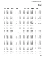
Page 429: ...95 Other Information Overview This chapter includes the following topics Topic Page Glossary 96 Contacting Sony 97 Troubleshooting 97 Specifications 103 Optional Accessories 104 Index 105 ...

Page 430: ...quipped audio video component such as a set top box DVD player and A V receiver HDMI supports enhanced or high definition video plus two channel digital audio National Television System Committee NTSC A unit of the Federal Communications Commission Washington DC that establishes television standards in the United States such as NTSC Color the standard used in this TV RF Radio Frequency That part o...

Page 431: ...rely to the wall outlet Locate the TV at least 3 4 feet away from fluorescent lights Cannot change channels with the remote control If you are using the TV to change channels first press the TV FUNCTION button If you are using another device to change channels be sure you have not inadvertently switched your TV from the channel 3 or 4 setting Use the Channel Fix option to fix the channel based on ...

Page 432: ...ble channels Check with your cable TV company for more information Check with your cable TV company if the channels are scrambled or encrypted You will need a CableCARD or a separate set top box to view those channels Some optional digital cable broadcast formats may not be supported If your cable TV company is broadcasting digital signals in unsupported broadcast formats you will need a separate ...

Page 433: ...or more files and rotating the image again Cannot Rotate Zoom Pan or Print Mark MPEG files These functions are available only for JPEG files Cannot show or hide file information in full screen or Slide Show Set the File Information option to On or Off see page 73 Cannot set print quantity The Memory Stick might be locked Unlock the Memory Stick and try setting the print quantity again Cannot see M...

Page 434: ...Problem Possible Remedies Problem Possible Remedies Good picture no sound Press MUTING so that the word Muting disappears from the screen see page 47 Make sure the Speaker option is set to On in the Audio Menu see page 81 Make sure the MTS option is set to Stereo or Mono see page 80 Cannot gain enough volume when using a cable box Increase the volume of the cable box using the cable box s remote c...

Page 435: ...feature set the Caption Vision option to Off If you were trying to select closed captioning select CC1 instead of TEXT 1 4 Bars appear at the top and bottom of the screen Some wide screen programs are filmed in aspect ratios that are greater than 16 9 such as 2 35 1 This is especially common with theatrical releases Your TV will show these programs with bars at the top and bottom of the screen For...

Page 436: ...an a minute this may indicate the TV needs service When lit indicates that the timer is set page 92 When the timer is set this LED will remain lit even when the TV is turned off Digital cable box does not work If you are connecting a VCR and digital cable box using a splitter as described on page 24 you must use a special bi directional splitter that is designed to work with your digital cable box...

Page 437: ... PB PR Y 1 0 Vp p 75 ohms unbalanced sync negative PB 0 7 Vp p 75 ohms PR 0 7 Vp p 75 ohms CONTROL S IN OUT 1 Variable Fixed Audio OUT 1 More than 408 mVrms at the maximum volume setting Variable More than 408 mVrms Fixed Impedance output 2 kilohms Digital Audio Optical Output PCM Dolby Digital 1 Optical Rectangular CableCARD Slot PCMCIA Type I II Supplied Accessories Remote Control RM Y199 AA R6 ...

Page 438: ...Use 220 W In Standby 3 W In CableCARD Standby 20 W KD 34XS955 In Use 250 W In Standby 3 W In CableCARD Standby 20 W KD 36XS955 In Use 270 W In Standby 3 W In CableCARD Standby 20 W Accessory Description Model Number Cables Audio Video VMC 810 820 830 HG Audio RKC 515HG Component Video VMC 10 30 HG TV Stands KD 30XS955 SU 30HX1 KD 34XS955 SU 34HX1 KD 36XS955 SU 36HX1 ...

Page 439: ...e Channels 58 closed caption modes 77 89 CODE SET button 47 color adjusting 78 Component Video Inputs 10 CONTROL S 40 CONTROL S IN OUT jacks described 14 Cool Color Temperature 78 D degauss 102 DIGITAL AUDIO OPTICAL jack 14 digital channels adding 84 Digital Reality Creation 10 DISPLAY button 52 DRC Mode 79 DRC MODE button 47 DRC See Digital Reality Creation DVD player using with TV remote control...

Page 440: ...1 Video options 79 Rewind button 47 S S VIDEO jack described 12 14 SAT CABLEFUNCTION button 47 SAT CABLE POWER button 47 satellite receiver using with TV remote control 59 Screen Mode 55 57 82 83 SCREEN MODE button 55 Setup Menu 89 sharpness adjusting 78 Simulated Effect 80 SLEEP button 47 speakers turning on off 81 using external speakers 81 specifications 104 Standard mode 78 Steady Sound descri...

Reviews: