background image

Chapter 1

Overview

Chapter 1

Overview

1-7

3

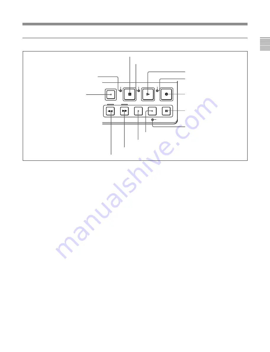
 Tape transport section

1

SHIFT button

Switches between functions for buttons with two
functions. The following buttons have two functions.

LIST/DOWN button: Becomes the LIST button

when the SHIFT button is pressed.

MARK/UP button: Becomes the MARK button

when the SHIFT button is pressed.

DATA/PLAY button: Becomes the DATA button

when the SHIFT button is pressed.

SEQ/REC button: Becomes the SEQ button when

the SHIFT button is pressed.

2

STANDBY indicator

Lights when the tape drum is rotating with tension
applied (standby on). It goes out when the drum stops
rotating and tension is released (standby off).
To protect the tape, the unit normally changes to
standby off when stop or pause mode continues for
longer than eight minutes. If you operate a dial or any
of the tape transport buttons except STOP/PAUSE
while the unit is in this state, the unit changes to
standby on and enters the mode of the button or dial
that you pressed.
Press the SHIFT and STOP buttons at the same time to
switch from standby on to standby off manually.

For more information about tape protection, see the setup
menu items in the 500s on page 6-13.

3

STOP button

Press this button, lighting it, to stop playback or
recording. When you stop playback, the monitor
displays E-E or still picture playback, depending on
the settings of the monitor output switches in the
timecode and setup menu section.
When setup menu item 105 is set to ON (page 6-8),
this button flashes if the reference video signal
specified in the OUT REF item of the submenu (page
2-22
) and item 309 in the setup menu (page 6-11) is
not being input.

For more information about reference video signal settings,
see page 2-7.

4

SERVO indicator

Lights when the drum servo and capstan servo are
locked.

5

DATA/PLAY button

Press this button, lighting it, to start playback.
Recording starts when you press this button together
with the SEQ/REC button 

7

, and manual editing

starts when you press this button together with the
EDIT button 

0

. If you press this button only during

recording or manual editing, recording or manual
editing stops and the unit returns to playback mode.
This button is also used to display the shot data if it is
recorded on the tape.

For details, see 5-1-3 “Reading Shot Data”.

STOP

DATA PLAY

SEQ REC

SHIFT

REW

F FWD

SEARCH

EDIT

PAUSE

STANDBY

SERVO

REC
INHI 

EDIT PRESET

7

SEQ/REC button

1

SHIFT button

3

STOP button

4

SERVO indicator

5

DATA/PLAY button

6

REC INHI indicator

8

PAUSE button

9

EDIT PRESET indicator

0

EDIT button

SEARCH button

!™

F FWD button

REW button

2

STANDBY indicator

Summary of Contents for DNW-A28

Page 1: ...DIGITAL VIDEOCASSETTE RECORDER DNW A28 A28P OPERATION MANUAL English 1st Edition Revised 3 ...

Page 2: ...rsuant to Subpart B of Part 15 of FCC Rules For the customers in Europe This product with the CE marking complies with the EMC Directive 89 336 EEC issued by the Commission of the European Community Compliance with this directive implies conformity to the following European standards EN55103 1 Electromagnetic Interference Emission EN55103 2 Electromagnetic Susceptibility Immunity This product is i...

Page 3: ...ording Timecode 2 12 2 6 2 Synchronizing the Internal Timecode Generator with an External Signal 2 14 2 6 3 Synchronizing the Internal Timecode Generator with Playback Timecode Timecode Recording during Auto Editing 2 15 2 6 4 Recording External Timecode without Regeneration 2 15 2 7 Submenu 2 16 2 7 1 Displays on the Home Page of the Submenu 2 16 2 7 2 Submenu Basic Operations 2 18 2 8 Input and ...

Page 4: ... 2 Shot Mark Operations 5 4 5 2 1 Reading Shot Marks 5 4 5 2 2 Writing Shot Marks 5 4 5 2 3 Creating a Virtual Shot Mark 5 5 5 2 4 Displaying Shot Mark List 5 5 5 2 5 Deleting Shot Marks 5 6 5 2 6 Sorting Shot Marks 5 7 5 2 7 Cueing up a Mark 5 7 Chapter 6 Setup Menu 6 1 Menu System Configuration 6 1 6 2 Basic Menu 6 1 6 2 1 Items in the Basic Menu 6 1 6 2 2 Basic Menu Operations 6 4 6 3 Extended ...

Page 5: ...ng sides use the Betacam SX format you can perform DMC editing You can also perform editing by connecting this unit to a VTR such as the DNW A100 A75 series Sequential recording Connecting two DNW A28 A28P units allows you to perform sequential recording from one unit to another When you perform overwrite recording using only two cassettes the last two hours recording can be obtained at any time W...

Page 6: ...he Betacam and Betacam SP formats only simple viewing is possible for tapes recorded in different mode Other Betacam SP cassettes and inexpensive UVW cassettes can be used in addition to Betacam SX cassettes Special high durability heads and components contribute to reduced maintenance costs You can stack up to three DNW A28 A28P units for use in recording and editing Features ...

Page 7: ...8P Microphone Video monitor Audio monitor Digital modulator Microwave transmission system Digital demodulator Protocol converter Protocol converter DNW A100 A75 series BVE series editor BVR 3 REMOTE REMOTE DC OUT VIDEO OUT MONITOR OUT AUDIO OUT BATTERY DC IN DC L90 BP 90 A DC 210 BKP L551 BP L90 A BP L60 A AC DN2A SDI DSM M1 DSM D1 SDI SDI SDI Network Digital cassette 1 2 System Configuration AC 5...

Page 8: ...2 EJECT button Press to eject the cassette The button lights while the cassette is being ejected If you insert a cassette which cannot be used on this unit the button flashes Press the button to eject the cassette 3 Jog dial Use to carry out searches in jog or shuttle mode and for menu operations Rotate downward to search in the forward direction and upward to search in the reverse direction For m...

Page 9: ...ibited regardless of the state of the cassette s erasure prevention plug The REC INHI indicator lights 9MONITOR switch Selects the output from the MONITOR OUTPUT L R connectors Settings made with this switch are enabled only when audio settings page 1 3 is selected 1 2 Output the audio signals of channel 1 from the L connector and the audio signals of channel 2 from the R connector MIX Output the ...

Page 10: ...D button Stops the progress of the timecode generator Press this button before setting timecode or user bits to hold those values For more information see section 2 6 Setting Timecode 3 RESET button Resets the CTL TC and U BIT values displayed in the FL display panel to 0 Resetting the CTL value erase all edit points that have been set For more information see section 2 6 Setting Timecode 4 SET bu...

Page 11: ... this button lighting it to stop playback or recording When you stop playback the monitor displays E E or still picture playback depending on the settings of the monitor output switches in the timecode and setup menu section When setup menu item 105 is set to ON page 6 8 this button flashes if the reference video signal specified in the OUT REF item of the submenu page 2 22 and item 309 in the set...

Page 12: ...nu in the FL display panel allowing you to select an edit mode For more information about the Edit Preset menu see section 3 1 Selecting an Edit Mode Press together with the DATA PLAY button 5 to perform manual editing To monitor E E mode You can monitor input signals in E E mode by pressing this button from stop mode The button lights when pressed and the input signals selected in the Edit Preset...

Page 13: ...knob and PRE VAR preset variable switch Adjusts the setup level in 525 60 mode and the black level in 625 50 mode The function of the knob changes as follows depending on the position of the PRE VAR switch PRE This is the normal setting Regardless of the knob position the setup level is set to the standard value VAR The setup level can be adjusted across a range of 30 IRE in 525 60 mode and the bl...

Page 14: ...hen it is set to VITC the VITC of input video signal For more information about the VITC LTC AUTO settings see page 2 17 7 PRESET REGEN regenerate switch Selects the value set in the internal timecode generator PRESET Preset the initial value of the timecode generated by the internal timecode generator either by a control panel operation or by remote control from the device connected to the REMOTE...

Page 15: ...th the REC PB audio level subadjustment knobs 2 by using the MAIN VR setting in the submenu see page 2 20 2 REC PB audio level subadjustment knobs and PRE VAR switches Make level adjustments by channel for audio input to this unit The function of the knobs changes as follows depending on the position of the PRE VAR switch PRE Preset to fixed levels Levels cannot be adjusted with the level adjustme...

Page 16: ...H 2 level switches 2 are set to 60 dBu phantom power is supplied to the AUDIO INPUT connectors when these switches are set to ON 2 AUDIO INPUT CH 1 CH 2 level switches Select the input level of the analog audio signals of input channels 1 and 2 60 dBu Microphone input 0 dBu Line audio input 4 dBu Line audio input 0 dBu 0 775 Vrms 2 AUDIO INPUT CH 1 CH 2 level switches 3 AUDIO INPUT CH 1 CH 2 conne...

Page 17: ...t the output level of the LEVEL knob with the MONITOR in the submenu For details see page 2 21 6 REF VIDEO IN reference video signal input connectors BNC type and 75 Ω termination switch Input a video signal with color burst VBS or monochrome video signal VS as reference video signal Set the 75 Ω termination switch to OFF when the signal is bridged and to ON when the signal is not bridged 7 VIDEO ...

Page 18: ...tor on the side of this unit connect the power cable of the BKP L551 When using the AC 550 550CE AC Adaptor connect to the DC output connector of the AC 550 550CE You can also use the DC 210 Battery Adaptor to connect a BP 90 A Battery Pack For more information see section 2 1 Power Preparations 6 TC OUT timecode output connector BNC type Outputs the following types of timecode depending on the VT...

Page 19: ...ly charged BP L90 Battery Pack To charge the battery pack Before use charge the battery pack with the BC L100 L100CE Battery Charger It takes about 2 5 hours to charge the BP L60 A and about 3 5 hours to charge the BP L90 A For more information about how to charge the battery pack refer to the manual for the BC L100 L100CE Chapter 2 Preparations 2 1 Power Preparations Battery Battery Adaptor Batte...

Page 20: ...e DC L90 Battery Adaptor 1 Mount the BP 90 A in the DC L90 1 Lift the lever up 2 Open the side cover 3 Insert the BP 90 A 4 Push the plug in 5 Close the side cover and pull the lever down 2 Attach the DC L90 to the side panel of this unit Use the same method that you use to attach the BP L60 A L90 A For details refer to To attach the battery pack on page 2 1 To connect to the DC IN connector Use t...

Page 21: ... panel of this unit and connect to AC power Use the same method that you use to attach the BP L60 A L90 A For details refer to To attach the battery pack on page 2 1 DC IN AC 550 550CE DC OUT DC power cord supplied with AC 550 550CE AC power cord supplied with AC 550 550CE To AC power POWER switch ON ...

Page 22: ... To input a reference video signal connect a 75 Ω coaxial cable with BNC plugs not supplied and set the REF VIDEO 75Ω termination switches as shown in the figure REF VIDEO 75Ω termination switch ON REF VIDEO 75Ω termination switch OFF a c c b Reference video signal Push cables a and b in the cable clamps The figure below shows how to connect two DNW A28 A28P units for editing Recording side VTR Pl...

Page 23: ...gure after checking the following points That ERROR 10 is not displayed in the FL display panel That there is no slack in the tape If ERROR 10 appears in the FL display panel This means that there is condensation inside the unit For the steps to take in this case see Moisture Condensation page A 3 If there is slack in the tape Take up the slack by rotating the reels in the directions shown by the ...

Page 24: ... of the capstan in the counterclockwise direction Note Perform the operation carefully so that edges of internal parts will not injure your hand Manual eject knob 3 Check that all tape has be wound into the cassette and eject the cassette by rotating the manual eject gear in the direction shown by the arrow 4 Attach the cover to the top panel 2 3 2 Preventing Accidental Erasures To make it impossi...

Page 25: ...about setup menu item 309 see page 6 11 For more information about the OUT REF see page 2 22 Setting Setting of setup menu item 309 AUTO AUTO1 AUTO2 EXT OUT REF setting REF INPUT Operating mode of this unit Recording a Input d Input Ref c Editing b See below Reference video signals in editing Other Ref a During recording to tape b When the assemble editing or insert editing mode has been selected ...

Page 26: ... note d of the table on previous page When a video signal is not being input synchronize with an external reference video signal When Ref is selected for the sync signal see note c of the table on previous page When an external reference video signal is not being input there is no external synchronization The servo reference video signal synchronizes with the output of the internal reference video...

Page 27: ...rmation using setup menu items 002 003 009 and 011 For details see pages 6 1 and 6 2 Note The example above shows the factory default configuration You can use setup menu item 005 to display a different type of time data in the second line as well For details see page 6 2 To display superimposed text information The figure below shows the time data and operation status that can be superimposed For...

Page 28: ...to editing segment The contents displayed in each block are listed on next page A B C a Displayed when this unit is used with an editor b Initial speed or speed stored in memory DMC edit mode DMC initial speed setting Information Displayed on the Monitor Display Operating Mode Block A Block B TAPE UNTHREAD No cassette loaded STANDBY OFF Standby off mode T RELEASE Tension release mode STOP Stop mod...

Page 29: ...or to the desired character then press the jog dial To delete a character from the data entry section Select Del in the character selection section To enter the date Select Date in the character selection section To enter the time Select Time in the character selection section Data entry section Character selection section Operation Cursor movement Rotate upwards Moves to the right When the last c...

Page 30: ...he INT EXT switch and the PRESET REGEN switch the following settings are made with submenus VITC ON OFF home page VITC LTC AUTO home page DF NDF 525 mode general settings page For more information about submenus see section 2 7 1 Displays on the Home Page of the Submenu INT EXT switch PRESET REGEN switch 1 PRESET 2 INT EXT 3 INT 4 PRESET PRESET PRESET 2 6 1 Setting an Initial Value and Recording T...

Page 31: ...y To set timecode to the current time 1 Set the F RUN R RUN switch to F RUN and the DF NDF in the submenu to DF in 525 mode only see page 2 23 2 Carry out steps 1 to 5 of To set an initial timecode value to set the timecode to a time slightly ahead of the current time 3 Press the SET button at the instant when the current time matches the displayed timecode To set user bits You can record up to 8 ...

Page 32: ...in an input video signal Proceed as follows 1 To synchronize with external timecode output LTC Connect the output of an external timecode generator or the timecode output of an external VTR to the TC IN connector To synchronize with the timecode VITC of an input video signal On the home page of the submenu select the input signal containing the VITC 2 Set switches and submenu items as follows Item...

Page 33: ...ESET REGEN settings fixed during automatic editing Item Setting VITC ON OFF home page Desired position ON when recording VITC VITC LTC AUTO home page VITC or LTC depending on which signal you want to synchronize with LTC when set to AUTO DF NDF general settings page No setting required ignored PB 4 3 3 INT EXT PRESET REGEN F RUN R RUN TC GENERATOR INT EXT EXT PRESET REGEN PRESET F RUN R RUN No set...

Page 34: ...ime data display area 1 Channel condition input video level display Depending on the unit s operating status one of the following is displayed here COND Displayed during playback The playback condition is displayed on a scale of three levels CONFI Displayed during crash recording when the CONFI is set to ON in video settings page 1 2 see page 2 22 The playback condition of recorded signals is disp...

Page 35: ...n press the MARK UP or LIST DOWN button If you select AUTO the type of timecode is distinguished automatically during playback VITC if the playback speed is within 1 2 and set to LTC during recording You can switch to the general settings page by pressing the PAGE button after pressing operation button F2 to highlight this display For details see the next section To switch between menu pages 9 VIT...

Page 36: ...ngs pages see section 2 8 Input and Output Settings for Video and Audio Signals Submenu To select an item Display the page that contains the item you want to select then press the operation button F1 to F4 that is located in the same column as the item The selected item is highlighted Press the button repeatedly until the item that you want to select is highlighted To change a setting With the ite...

Page 37: ...AU 1 LTC VITC ON SDI b b b MIX SWP PAGE PAGE PAGE PAGE PAGE PAGE PAGE DOWN LIST MARK UP F1 F2 F3 F4 F1 F2 F3 F4 F4 F1 F1 AU 1 F1 F1 F1 F1 Home page a Audio 1 1 Audio 1 2 Audio 2 1 Audio 1 3 Home General settings Home Video 1 2 Video 2 2 Home a When the unit is first powered on and when you return to the home page none of the items on the page are highlighted b You can return to the home page by ke...

Page 38: ...MIX SWAP CH 1 to 4 Select up to two audio input signals IN 1 to IN 4 to be assigned to channels 1 to 4 When two signals are selected they are mixed To select Select the channel using operation buttons F1 to F4 and press the MARK UP or LIST DOWN button to add asterisks to the position of the desired input signal Item Setting AGC Turn the audio input AGC circuits ON and OFF enabled when the REC PB a...

Page 39: ...ettings subpage appears as shown below To return to the home page Press the PAGE button Contents of the audio settings subpage By pressing operation buttons F1 to F3 you can make the following three settings for mixing of input signals in audio channels 1 and 2 The selected setting is highlighted To select input signals use audio settings page 1 1 MIX OFF Assign IN 1 to channel 1 and assign IN 2 t...

Page 40: ...oma output level Setup level 525 60 mode Black level 625 50 mode Chroma phase Y C delay Sync subcarrier phase Y C DELAY When the PROCESS CONTROL is set to PANEL set the Y C delay value PRESET Fixed at factory default level VAR Adjustable as desired To adjust Press operation button F4 to indicate the VAR press F4 again to highlight the value and then press the MARK UP or LIST DOWN button to change ...

Page 41: ...ded CB100 625 mode 100 color bar signal CB75 525 mode 75 color bar signal CB75R 75 color bar signal reverse BOW Bowtie signal PLSBR Pulse bar signal MLTBS Multi burst signal HSWP H sweep signal 5STEP 5 step signal RAMP Ramp signal SH Shallow ramp signal RED Red signal GRAY 50 flat signal WHITE 100 flat signal BB Black burst signal SDI SDI check field signal NTC7 NTC 7 test signal selectable only i...

Page 42: ...2 to ON see page 6 18 4F Lock the capstan servo on 4 fields 8F Lock the capstan servo on 8 fields 625 system only 3 DF NDF setting in 525 mode Select DF to advance timecode in drop frame mode and NDF to advance timecode in non drop frame mode 4 KEY INH key inhibit setting Set to ON to disable the buttons on the control panel Submenu operations can still be performed even when this item is set to O...

Page 43: ...ggle between ON and OFF when the ON OFF display of the desired item is highlighted If the ON OFF display of the desired item is not highlighted release the EDIT button and again press and hold it See the following section in the right column Edit Preset menu operations To toggle a menu item between ON and OFF With the ON OFF display highlighted press the corresponding operation button F1 to F4 To ...

Page 44: ...ng one or more of VIDEO TC timecode and A CH1 to A Ch4 audio of channels 1 to 4 to ON You can toggle between ON and OFF when the ON OFF display of the desired item is highlighted If the ON OFF display of the desired item is not highlighted release the EDIT button and again press and hold it For more information about using the Edit Preset menu see Edit Preset menu operations on the previous page S...

Page 45: ...corded in Betacam Betacam SP format the playback speed range is between 10 times normal speed 19 steps 3 2 Finding Edit Points Search Switching between each mode To put this unit into a search mode press the SEARCH button or rotate the jog dial When you press the SEARCH button the unit enters the most recently used search mode When you rotate the jog dial the unit enters jog mode To switch between...

Page 46: ...h the recording side VTR in stop mode 2 Select the edit mode 3 Press the DATA PLAY button The recording side VTR starts playback Note About 2 seconds are required for the picture to stabilize You should begin playback at a point on the tape more than 2 seconds in advance of the section you will use in the edit 4 Press the EDIT button together with the DATA PLAY button at the point where you want t...

Page 47: ...ct the external reference signal for preread editing When preread mode is selected this unit will not shift into E E mode in any operation mode to avoid oscillation caused by the loop connection When preread mode is turned off however the E E signal is output and oscillation may occur if connection between the input and output of the same channel is not removed after preread editing To prevent the...

Page 48: ......

Page 49: ...code see page 2 12 To adjust audio input level Set the REC PB audio level PRE VAR subadjustment switches to VAR Turn the REC PB audio level subadjustment knobs monitoring the input levels indicated by audio level meter Instead of using the REC PB audio level subadjustment knobs you can adjust the input level with the REC PB audio level main adjustment knobs To do so set MAIN VR on the submenu to R...

Page 50: ...C LOCAL REMOTE SHIFT STANDBY SERVO REC INHI 5 4 5 Simultaneously press the second VTR s SHIFT button SEQ REC button and DATA PLAY button The starting VTR begins recording The STANDBY indicator of the second VTR goes out The second VTR starts recording automatically when the remaining time of the tape reaches 2 minutes on the currently recording VTR The setting of Setup menu item 014 affects what h...

Page 51: ...you pressed the PAUSE button and the unit enters recording pause mode Note When recording is paused do not do any of the following Back space editing will be interrupted Eject a cassette Play back rewind or fast forward the tape Press the STOP button 3 At the next scene press the PAUSE button The tape moves to the recording start position and recording starts 4 Repeat steps 2 and 3 to record more ...

Page 52: ...read by the timecode reader can be output from the TC OUT connector Select REGEN in setup menu item 606 see page 6 15 set the INT EXT switch to INT and the PRESET REGEN switch to REGEN 4 4 2 Playback Operation Confirm the recording format of the cassette SX SP or OX indicated on the FL display panel Then perform the following procedure 1 Press the DATA PLAY button Playback starts To adjust headpho...

Page 53: ...djust the playback speed using either method a or b a Holding down the DATA PLAY button rotate the jog dial The adjustment range is 15 in steps of 1 b Holding down the DATA PLAY button press the MARK UP or LIST DOWN button The adjustment range is 8 2 Release the DATA PLAY button when the adjustment is completed The VTR returns to normal speed playback and the SERVO indicator lights 00 00 00 00 AU ...

Page 54: ......

Page 55: ...reate shot mark lists by reading in only the specified shot mark types and delete all or a part of data in a list when it is no longer needed For more information about shot marks refer to the Operation Manual of your Betacam SX camcorder 2 Writing and deleting shot marks You can use the Shot Mark Operation menu to specify whether REC Start marks are recorded You can write additional shot marks at...

Page 56: ... marks ON OFF shot mark 1 Include Shot Mark 1 ON OFF shot mark 2 Include Shot Mark 2 ON OFF post mark Include Post Mark ON OFF Select the type of marks written during recording and in assemble mode shot mark 1 shot mark 2 post mark REC START MARK MODE Select whether to record REC Start marks for each operating mode crash REC Write REC Start marks in crash REC mode ON OFF assemble Write REC Start m...

Page 57: ...DNW 0090 TIME 12 55 10 CASSETTE NUMBER 0095 ID1 AAAAAAAAAAAA SHOT NUMBER 0052 ID2 BBBBBBBBBBBB ID3 CCCCCCCCCCCC ID4 DDDDDDDDDDDD TCR 23 59 59 29 Serial number Time Cassette number Shot number Camera ID Recorded timecode Date Name of shooting device The contents of the display change as the shooting conditions change for example the date and time or shooting device change Sections where no data is ...

Page 58: ... cassette and the data of the next cassette To read only selected mark types If you need only a specific mark type use item G02 on the Shot Mark Operation menu to select that type 5 2 2 Writing Shot Marks To write REC Start marks You can write REC Start marks during crash REC assemble and insert mode Under item G03 of the Shot Mark Operation menu change the setting of the mode you want to use to O...

Page 59: ...5 12 4 V 10 07 05 11 SHOT MARK Mark type R REC Start S1 Shot Mark 1 S2 Shot Mark 2 V Virtual Shot Mark P Post Mark Memo mark Selection mark Shows the cue up shot mark To select a mark Rotate the jog dial to move the selection mark to the left of the number of the mark you want to select To attach a memo mark Select the mark to which you want to attach the memo mark then press the SET button Detach...

Page 60: ...button Deleting the list Press and hold operation button F1 and press the LIST DOWN button while holding operation button F1 5 2 5 Deleting Shot Marks You can select shot marks from the list and delete them from the tape To delete shot marks press the MARK UP button and keep it pressed 2 seconds or longer to put the unit into shot mark write and delete mode the SHIFT button flashes Display the sho...

Page 61: ...n timecode order 1 With the shot mark list displayed press the STOP button together with the SET button The mark selection screen appears 2 Rotate the jog dial to select SORTING LIST and press the dial 3 Rotate the jog dial to change the setting to ON Sorting of the list starts When sorting finishes the setting returns to OFF To return the list to its original state Press operation button F1 while...

Page 62: ......

Page 63: ...al value which is superimposed on output from the VIDEO OUTPUT 2 SUPER connector and display on the monitor 00 56 6A 525 mode 107 steps 00 6A 81 625 mode 130 steps The hexadecimal value 00 is for the top of the screen Increasing the value lowers the position of the characters Adjust the horizontal screen position of the character information as a hexadecimal value which is superimposed on output f...

Page 64: ...ches are disabled ST EJ Only the STOP button and EJECT button are enabled ENA All buttons and switches are enabled 007 TAPE TIMER DISPLAY Determines whether to display the CTL count in 12 hour mode or 24 hour mode 12H 12 hour mode 24H 24 hour mode 008 MONITORING SELECTION FOR VTR TO VTR EDIT For editing with two DNW A28 A28P units determines whether the recording side VTR is forced into E E mode t...

Page 65: ...Exchange the cassettes when one sequential recording finishes AUTOMATIC OVERWRITE Do sequential recording overlaying previously recorded contents Do not exchange cassettes B01 RECALL BANK 1 Set to ON to recall menu settings from menu bank 1 B02 RECALL BANK 2 Set to ON to recall menu settings from menu bank 2 B03 RECALL BANK 3 B04 RECALL BANK 4 Set to ON to recall menu settings from menu bank 4 B11...

Page 66: ...tor and on the FL display panel MENU button 00 00 00 00 AU 1 AUTO VITCON SDI TC 525 SX BATT FL display panel Changing the currently displayed menu item Turn the jog dial Turning the dial downward increments the item number and turning it upward decrements the item number When the desined menu item is displayed press the dial Changing a menu item setting value To change the setting value of the cur...

Page 67: ...gain The settings are saved and the menu display disappears Switching between 525 625 line systems menu item 013 Using the following procedure you can set basic menu item 013 525 625 SYSTEM SELECT to ON and then switch between 525 NTSC and 625 PAL The following procedure shows by way of example how to switch from a 525 NTSC system to a 625 PAL system Note After switching playback of Betacam Betaca...

Page 68: ...FL display panel Menu bank operations menu items B01 to B14 This unit allows four different complete sets of menu settings to be saved in both 525 and 625 modes in what are termed menu banks numbered 1 to 4 Saved sets of menu settings can be recalled for use as required To access to menu item B01 quickly You can recall any required menu item by turning the jog dial after pressing the MENU button I...

Page 69: ...all Save Menu bank 1 Recall Save Menu bank 2 Recall Save Menu bank 3 Recall Save Menu bank 4 Recall Save Menu bank 1 Recall Save Menu bank 2 Recall Save Menu bank 3 Recall Save Menu bank 4 525 mode 625 mode Current menu settings Current menu settings ...

Page 70: ... at all times except during recording editing KEY The SEARCH button must be pressed to switch to search mode selected last 106 CAPSTAN LOCK Select whether or not to display a warning when the video audio reference signal selected by the OUT REF in the submenu is not supplied or is out of phase with the input video signal OFF No warning ON Flash the STOP button as a warning 107 108 AUTO EE SELECT W...

Page 71: ...times normal speed 120 CTL LOCK IN VAR SHTL Select whether the tape transport should be phase locked to the CTL during playback in variable or shuttle mode OFF Not phase locked ON Phase locked at the following speeds 1 0 5 0 5 and 1 0 times normal 122 AUTO EE WITH ANALOG TAPE Select whether or not the setting of item 108 also applies to a cassette recorded in Betacam Betacam SP format Item 108 sel...

Page 72: ... 1 the speed selected in this range 0 03 0 1 0 2 0 5 and 1 times normal speed can be selected Extended Menu 307 AUTO DELETION FOR INCONSISTENT DATA Select what happens when an erroneous edit point is set MANU A warning is given by flashing the DELETE button The operator must manually delete the unnecessary edit point NEG E When inconsistent edit points are set such as when an OUT point is before a...

Page 73: ...s inhibited Select this setting when you wish to carry out assemble editing Note When the REC INHI switch is set to ON the REC INHI indicator on the control panel lights If an operation inhibited by this item is attempted the REC INHI indicator flashes Item number Item name Settings 311 ANALOG AUDIO EDIT PRESET REPLACE FOR CH 1 Select how to activate the CH 1 edit preset of the unit NO DEFINITION ...

Page 74: ...is not carried out and the unit stops ON The editing is automatically retried up to twice 319 PREREAD SELECT Select the signals used for preread editing A V Both audio and video signals AUDIO Audio signal only VIDEO Video signal only 320 DIGITAL AUDIO PB PROCESS ON EDIT POINT Select the treatment of audio at edit points CUT Carry out a cut possibly resulting in audio discontinuities at the edit po...

Page 75: ...3 AUTOMATIC PREROLL REFERENCE ENTRY Select whether or not the edit IN point is automatically set by pressing the PREROLL button when the IN point is not set before starting preroll DIS IN point is not set automatically ENA IN point is set automatically Item number Item name Settings STILL TIMER Select the time delay from the tape transport stopping either the STOP PAUSE mode or the still playback ...

Page 76: ...ET Select whether or not to set the ID code OFF Do not set the ID code ON Set the ID code To set the ID code 1 Set this item to ON The time data display area in the FL display panel flashes 2 Turn the jog dial to select the column then hold down the SEARCH button while turning the jog dial to change the digit value 3 When the ID code setting is complete press the SET button This saves the ID code ...

Page 77: ...eo signal and the timecode When AUTO is selected color framing is controlled as follows according to the operating mode of the timecode generator In INT PRESET mode the INT EXT switch is set to INT the PRESET REGEN switch is set to PRESET and in modes other than the automatic editing mode the timecode is generated with color framing locked to the video signal and the color framing flag is set In I...

Page 78: ...h can be specified in this menu item THROU Regardless of the setting of other sub items switch off blanking for all lines which can be specified in this menu item In 525 mode 12 20 LINE 12 LINE 20 Specify blanking for lines 12 to 20 BLANK Carry out blanking THROU Switch off blanking 21 LINE 21 Specify blanking for line 21 BLANK Carry out blanking HALF Carry out half blanking THROU Switch off blank...

Page 79: ...oiseless variable playback when the playback signal is an odd field and the reference signal is an even field the playback signal is shifted by 1H 1 line to suppress the vertical movement of the playback picture Y add function This item selects whether or not to apply a 1H shift to the vertical blanking interval ON Carry out vertical blanking shift OFF Do not carry out vertical blanking shift Note...

Page 80: ...e input signal It is not carried out with respect to other input signals The setup amounts specified in this menu item have no connection with the SETUP BLACK LEVEL knob Sub Item 0 MASTER LEVEL When the input signal Betacam playback signal and output signal settings are MSTER master the setup amount specified for this sub item is removed from the input signal and Betacam playback signal and is add...

Page 81: ... are disabled Menu items in the 700s relating to video control continued Item number Item name Settings 723 INPUT VIDEO BLANK Switch blanking on or off for individual lines in the vertical blanking interval of an input video signal The Y C signal and odd even fields are blanked simultaneously A signal with blanking carried out according to this setting is recorded Sub Item 0 ALL LINE Specify the b...

Page 82: ...signal output phase is the same as the output phase in the E E mode Use this setting when editing with a single VTR or when previewing while watching the VTR output signal EXT The video playback signal output phase is the same as the phase of an input video signal or external reference signal Note Whichever setting is used the correct editing results will be obtained When however you are using an ...

Page 83: ...cam playback analog audio signals supplied to the MONITOR OUTPUT connector ADD Simple addition RMS Root mean square AVE Simple average 807 AUDIO OUTPUT PHASE Select the output timing of a digital audio playback signal SDI only The reference position corresponds to a setting of 80H when the setting is less than 80H the output timing is advanced and when it is higher than 80H the output timing is de...

Page 84: ...ck of a composite signal in jog or variable mode according to the setting of item 705 the data will be subject to ESR edge subcarrier reducer processing 912 SEQUENTIAL RECORD INPUT SIGNAL Selects the signal input method for sequential recording PARALLEL The video and audio signals you will record are input to the each VTR separately CASCADE The video and audio signals you will record are input to ...

Page 85: ...he cleaning cassette carefully as inappropriate use of the cleaning cassette may damage the heads To carry out head cleaning use the following procedure 1 Insert the cleaning cassette 2 Press the EJECT button while holding down DATA PLAY button Head cleaning starts After a head cleaning operation which lasts for about 5 seconds the cleaning cassette is automatically ejected Note When carrying out ...

Page 86: ...in REC or PLAY mode 08 DRUM TROUBLE Drum motor malfunction was detected 09 FUNC CAM TROUBLE Threading or unthreading malfunction was detected 10 HUMID Condensation was detected 12 TAPE TOP SENSOR Tape top sensor malfunction was detected 13 TAPE END SENSOR Tape end sensor malfunction was detected 14 FAN MOTOR Cooling fan motor malfunction was detected 40 DPR 87 BOARD 1 Abnormal operation of IC on D...

Page 87: ... location There may be moisture condensation on the tape Wait until the tape warms Regular Checks Digital Hours Meter The hours meter can display seven items of information in corresponding display modes about the operational history of the unit Use it as a guide in scheduling periodic maintenance Display modes of the hours meter H01 OPERATION mode Displays the total number of hours the unit has b...

Page 88: ...ents depends on the particular conditions of use In particular depending on the degree of dirt contamination and abrasion pinch rollers and cleaners may require replacement earlier than suggested by this table Regular Checks Components Part No a When the DJH 20A drum assembly is replaced the DJR 20A upper drum assembly and 4ch RP slip ring assembly are also replaced Timing for replacing components...

Page 89: ...ack speed Servo lock time 0 5 seconds or less from standby on 2FD Lock Load unload time Load time Approx 8 seconds Unload time Approx 5 seconds Specifications Recommended cassettes Betacam SX cassette S BCT 6SX 12SX 22SX 32SX 60SX Betacam SP cassette S for both recording and playback Betacam cassette S only for playback Video system Digital video signal system Sampling frequency Y 13 5 MHz R Y B Y...

Page 90: ...tal tape Oxide tape Bandwidth Y 30Hz to 4 5MHz 0 5 dB 4 0dB 30Hz to 4 1MHz 0 5 dB 6 0dB R Y B Y 30Hz to 1 5MHz 0 5 dB 3 0dB 30Hz to 1 5MHz 0 5 dB 3 0dB S N Y 51 dB or more 48 dB or more R Y B Y 48 dB or more 45 dB or more K factor 2T pulse 2 or less 3 or less LF non linearity Y 3 or less Y C delay 20 ns or less R Y B Y 4 or less Metal tape Oxide tape Frequency response a 50 Hz to 15 kHz 1 5 dB 3 0...

Page 91: ...l 3 dist Level b at 3 distortion level CCIR 468 3 weighted c THD at 1kHz reference level 4 dBm Processor adjustment range Video level 3 dB to 3 dB selectable Chroma level 3 dB to 3 dB selectable Setup level 525 mode 30 IRE Black level 625 mode 210 mV Y C delay 100 ns in Betacam Betacam SP playback Chroma phase 30 System phase Sync 15 µs SC step SC 200 ns Input connectors SDI IN BNC 1 Serial digita...

Page 92: ...k to 20 dBu at 8 Ω load unbalanced Remote connectors REMOTE D sub 9 pin female AUX Accessories supplied Operation Manual 1 Installation Manual 1 Optional accessories AC DN2A AC Adaptor AC 550 550CE AC Adaptor BP L60 A L90 A Battery Pack BP 90 A Battery Pack BC L100 L100CE L50 Battery Charger for BP L60 A L90 A BC 210 210CE Battery Charger for BP 90 A BC 410 410CE Battery Charger for BP 90 A DC L90...

Page 93: ...d for adjusting input signal levels Emphasis The signal is emphasized at high frequencies During playback it is de emphasized This suppresses noise without affecting the original signal External lock Synchronizing one equipment slave unit to another master unit The signal and tape run of the VTRs used for editing player and recorder are usually synchronized Head drum A metal cylinder to which a vi...

Page 94: ...heads the device automatically switches from standby on mode to standby off mode after a certain period of time Subcarrier Color information contained in a composite video signal Its amplitude is for color saturation and its phase to color burst is for hue Superimpose To put one picture or characters onto another so that both can be seen at the same time Sync A reference signal consisting of verti...

Page 95: ...reviation of Vertical Interval Time Code This timecode is inserted in the vertical blanking interval and recorded on the video tracks It can be read at low speeds and during still playback but not during high speed playback See also LTC ...

Page 96: ......

Page 97: ...rtment 1 4 Channel condition 2 16 CHROMA knob and PRE VAR switch 1 9 Chroma phase 1 9 2 22 CHROMA PHASE knob and PRE VAR switch 1 9 Chroma output level 1 9 2 22 Components A 4 Condensation A 3 CONFI submenu 2 22 Connection 2 4 Connector panel rear panel 1 12 Control panel front panel 1 4 setup menu items 6 8 CTL displaying 1 6 2 16 resetting 1 6 CTL TC U BIT button 1 6 D DATA PLAY button 1 7 DC IN...

Page 98: ...r 1 14 SDI OUT connector 1 14 Search 3 3 switching between modes 3 3 switching to normal playback 3 3 SEARCH button 1 8 SEQ REC button 1 8 Sequential recording 4 2 SERVO indicator 1 7 Servo lock 1 7 2 24 6 8 reference video signal 2 7 SET button 1 6 SET UP BLACK LEVEL knob and PRE VAR switch 1 9 Setup level 525 60 mode 1 9 2 22 Setup menu 6 1 basic menu 6 1 configuration 6 1 displaying 6 4 extende...

Page 99: ... VFD BR submenu 2 24 VID SG submenu 2 23 Video input level composite signal 2 16 2 22 input output connectors 1 13 output level 1 9 2 22 setting submenu 2 22 signal generator VID SG 2 23 source signal selection 2 17 Video control operation section lower control panel 1 9 PROCESS CONTROL submenu 2 22 setup menu item 6 16 VIDEO IN submenu 2 22 VIDEO INPUT connectors and 75 Ω termination switch 1 13 ...

Page 100: ......

Page 101: ...des acquéreurs de l équipement décrit dans ce manuel Sony Corporation interdit formellement la copie de quelque partie que ce soit de ce manuel ou son emploi pour tout autre but que des opérations ou entretiens de l équipement à moins d une permission écrite de Sony Corporation Das in dieser Anleitung enthaltene Material besteht aus Informationen die Eigentum der Sony Corporation sind und ausschli...

Page 102: ...DNW A28 A28P SY 3 867 690 04 1 Printed in Japan 2001 06 13 1999 Sony Corporation B P Company ...

Reviews: