24
Chapter 2 Locations and Functions of Parts and Controls
Chapter 2 Locations and Functions of Parts and Controls
Locations and Functions of Parts and Controls
SOURCES
CR MONITOR
PROGRAM
ACCESS
PGM
AUX
MTR
SETUP
DIM
CUT
EXT
2T-1
2T-2
10
5
0
5
10
20
30
40
60
10
5
0
5
10
20
30
40
60
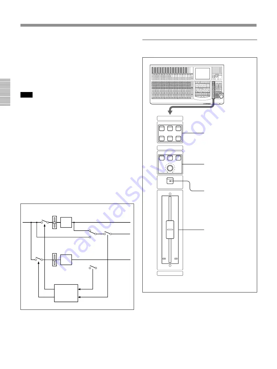
Control room monitor section
1
SOURCE section
2
CR MONITOR section
PGM bus section
3
ACCESS button
4
PROGRAM fader
CUT
FADER
PAN
SOLO
LOGIC
SOLO MODE
SOLO SW
AFL
PFL
4
SOLO MODE section
Changes the function of the channel SOLO buttons.
SOLO button:
When this button is lit, the SOLO
buttons on the channel strip panel function as
‘destructive solo’ buttons and cause all other channels
to cut.
For detailed information on how to set SOLO disabled, see
“SOLO buttons” on the MONITOR window on page 69.
Note
The solo mode affects both monitoring and the mix
output. The solo mode is operational for stereo pan
and surround sound MTR bus monitoring.
AFL (after-fader listening) button:
When this button
is lit, the SOLO buttons on the channel strip panel
function as the AFL buttons. The AFL signal is sent to
the monitor, regardless of the settings in the FADERS
section.
PFL (pre-fader listening) button:
When this button
is lit, the SOLO buttons on the channel strip panel
function as the PFL buttons. The PFL signal is sent to
the monitor, regardless of the settings in the FADERS
section.
CANCEL button:
Provides an automatic method of
cancelling all SOLO’d channels (set in SOLO mode).
CUT
PAN
SOLO
PGM
MTR
AFL/PFL
5
HEADPHONES control
Adjusts the volume of the headphones.
Control room monitor section and PGM
bus section
1
SOURCE section
Selects the signal for the control room monitor (which
is output to the CR MONITOR connector on the rear
panel).
EXT button:
When this button is lit, the EXT
MONITOR signal selected on the MONITOR window
(page 67) is monitored.
2T-1 button:
When this button is lit, the signal input
to the 2TR IN 1 connector is monitored.
Summary of Contents for DMX-R100
Page 4: ...4 ...
Page 131: ...131 Appendix Appendix Block Diagram Fs 44 1 48 kHz 1 fs ...
Page 132: ...132 Appendix Appendix Fs 88 2 96 kHz 2 fs Block Diagram ...
Page 133: ......
Page 134: ...Sony Corporation Printed in Japan ...


