background image

46

Chapter 4  Commands

BARCODE SEARCH

This command is used to obtain bar code information for all the media.
The library detects bar code information for slots where media is set, but does 
not detect if media is inserted. If you need to detect the presence of media, 
execute the CTG INVENTORY operation in advance.

When you want to obtain bar code information of media in the drive, execute 
the MOVE MEDIUM operation first. Then after the medium is put back into the 
slot from the drive, perform the BARCODE SEARCH command. 

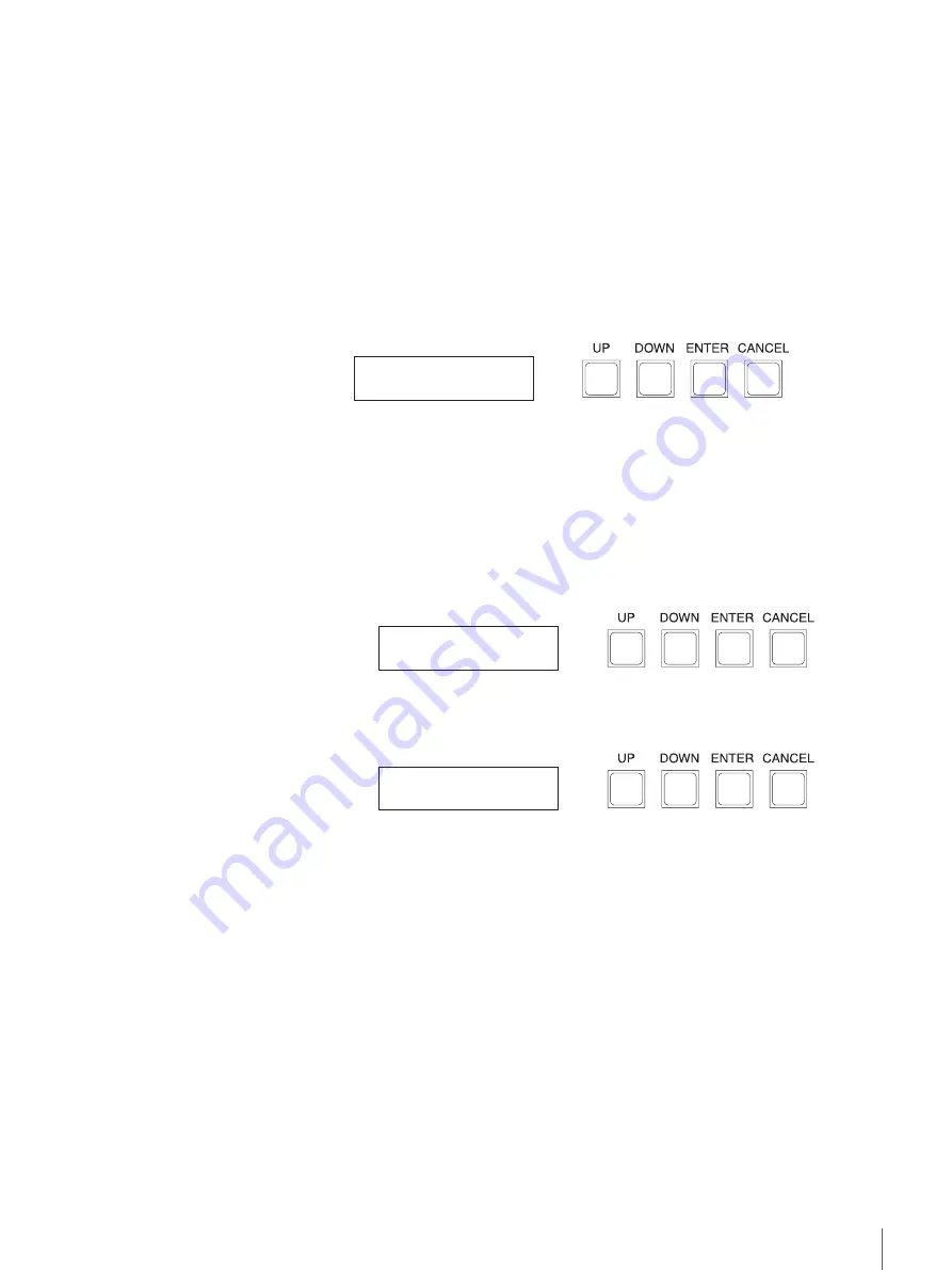
Press the “Enter” button when the command menu is displayed, and the LCD 
panel display changes as follows. The library is now in Command execution 
mode. 

Button Operations

“Up” button and “Down” button: No associated function.
“Enter” button: 

Obtains bar code information.  
It may take several minutes depending on the 
number of media.

“Cancel” button: 

Returns to the command menu.

When the command ends normally

The following display appears. 

When the command ends abnormally

The following display appears. 

Button Operations

“Up” button and “Down” button: No associated function.
“Enter” button: 

No associated function.

“Cancel” button: 

Returns to the command menu. 

BARCODE SEARCH
  Push ENTER Key.

BARCODE SEARCH
COMPLETED

BARCODE SEARCH
ERROR * * / * *  * *

Summary of Contents for csm-20s

Page 1: ...CSM 20S 2005 Sony Corporation 2 634 578 12 1 S AIT Library Operating Instructions Before operating the unit please read this manual thoroughly and retain it for future reference ...

Page 2: ...chtung Zur Trennung vom Netz ist der Netzstecker aus der Steckdose zu ziehen welche sich in der Nähe des Gerätes befinden muß und leicht zugänglich sein soll Hinweis Die 3 adrige Geräteanschlußleitung muß Typ H05VV F oder H05VVH2 F sein und nach DIN VDE 0625 geprüft sein Der Stecker und die Gerätesteckdose müssen nach DIN VDE 0620 bzw DIN VDE 0625 geprüft sein Der Leitungsquerschnitt kann 0 5mm2 b...

Page 3: ...id your authority to operate this equipment Note This equipment has been tested and found to comply with the limits for a Class A digital device pursuant to Part 15 of the FCC Rules These limits are designed to provide reasonable protection against harmful interference when the equipment is operated in a commercial environment This equipment generates uses and can radiate radio frequency energy an...

Page 4: ...s 11 Front 11 Rear 13 About the label 14 Chapter 2 Installation Overview 15 Unpacking 15 Package Contents 17 Preparing the Host Computer 17 Installing the S AIT Library 18 Connecting the Power Cable 19 Connecting the SCSI Bus Cable 20 Chapter 3 Operation Overview 22 Using the Device 22 Front Panel of the Device 23 LCD Panel and Control Buttons 23 LED 23 Operation Modes 24 ON LINE Mode 24 USER Mode...

Page 5: ...hen a Warning Occurred in the Drives 63 When an Interruption Occurred in the ACI Communication with the Drives 64 Display When a Warning and an Error Occurred in the drives at the Same Time 65 When an Error Warning occurred in Both the Library and the Drives at the Same Time 66 Chapter 6 Using the Media Compatible Cartridges 67 Data Cartridge 67 Components and Functions 68 Setting the Write protec...

Page 6: ...05 Sony Corporation All rights reserved Trademarks Sony Advanced Intelligent Tape and Super Advanced Intelligent Tape are trademarks or registered trademarks of Sony Corporation in this country other countries or both Other product names are trademarks or registered trademarks of their respective owners in this country other countries or both ...

Page 7: ...IT media is based on AME technology This technology represents the culmination of over 50 years of Sony innovation and experience in magnetic tape technology The AME tape formulation with diamond like carbon coating offers an extraordinary durability and reliability up to 30 000 media passes and an estimated media archival life of up to 30 years Remote Memory in Cassette R MIC The non volatile R M...

Page 8: ... swappable units they can be added or replaced even while the power is on If you want to install an additional S AIT drive please contact your dealer The S AIT library can be remotely controlled A browser can be used to configure individual settings It can also be used to view library and maintenance information For details see the operating instructions of S AIT Library Administration Tool Like t...

Page 9: ...sed with the S AIT library and supported operating systems contact your dealer Usage Precautions Important Information About Safety Power Precautions Only use 100 240 V AC Avoid plugging the unit to the same power outlet as high current equipment such as copiers or shredders Power Cable Precautions Do not crush the cable or place heavy objects on it If the cable insulation appears worn or broken d...

Page 10: ...own could result in back injury or other accidents resulting in injury or damage to the S AIT library Usage Precautions Environmental Considerations Do not store or use the unit in locations subject to high humidity high temperature direct sunlight excessive dust intense vibrations sudden changes in temperature Proper Ventilation To avoid overheating install the unit where air can circulate freely...

Page 11: ...ur application software And the shutter automatically closed when a cartridge is inserted The port is protected by a shutter that prevents dust from entering the device D Control Buttons Used to execute commands See Commands on page 34 for details E LCD Panel Displays the commands and operation mode on two 16 character lines See LCD Panel and Control Buttons on page 23 for details F Error Warning ...

Page 12: ...azines when the front door is opened It may cause a failure of the library When you remove a magazine never put your hand inside the dock while the library is powered on If you put your hand at the back of magazines it may cause an injury with your hand caught in the dock Note Cartridges are not assembled when the front door is open Make sure to close the front door after replacing magazines Once ...

Page 13: ...t how to add or replace drives F SCSI Connector 1 right side SCSI Connector 2 left side Connect the SCSI cable to this connector For details about connection see Connecting the SCSI Bus Cable on page 20 G RS 232C Connector For service use only You do not normally need to use this connector H Cooling Fan Ventilation Hole Be careful not to block the ventilation holes If you do the drive in the unit ...

Page 14: ... unit together with the serial number Refer to the model and serial numbers on the label when seeking technical support B Serial number The serial number is located on the rear of the unit together with the model number Refer to the serial and model numbers on the label when seeking technical support 1 2 ...

Page 15: ...Caution With a single drive installed the S AIT library weighs approximately 27 kg 59 5 lbs At least two people are needed in order to handle the library Handling the S AIT library on your own could result in back injury or other accidents resulting in injury or damage to the S AIT library Note You will need the box and packing materials if you wish to move or transport the unit Retain them for fu...

Page 16: ...damage immediately by contacting your dealer 3 Remove transport screws 1 and 2 M4 on the left side as illustrated 4 Remove transport screw 3 M3 with nut on the right side as illustrated 5 Remove screws M3 for drive on the top of the unit as illustrated Screws for drive 1 one drive Screws for drive 2 only two drives ...

Page 17: ...y are indicated on the package Download the Operating Instructions and device driver from the Sony Web site http www sony net Products storagesolution Preparing the Host Computer Prepare the host computer before installing the S AIT library 1 Make sure that a SCSI host adapter card is installed in the host computer 2 Install all the necessary software supporting the unit on the host computer For d...

Page 18: ...y on a horizontal surface near an AC power outlet Make sure that you leave gap of about 150 mm 5 9 in behind the rear of the unit to allow air to circulate Recommended positioning of the unit Always position the unit horizontally Away from moving air such as fans open windows or air conditioners Away from devices such as facsimiles to avoid toner and paper dust Caution The S AIT library should not...

Page 19: ...s the AC IN connector receptacle 2 Connect one end of the power cable to the AC IN connector and the other end to the power outlet Note If the S AIT library does not come with a power cable make sure that you connect a power cable appropriate for your country to this connector Note When you remove the cartridge magazine DO NOT touch inside the unit while it is on Doing so may lead to injury AC Pow...

Page 20: ...t the supplied terminator to the open connector Make sure that the SCSI connectors are securely connected With LVD Low Voltage Differential SCSI make the total length of the SCSI cable internal and external connecting the host computer and the device at the end of the SCSI bus shorter than 12 m 39 4 ft The S AIT library internal cable length is 2 m 80 in SCSI cables cannot be branched A SCSI bus a...

Page 21: ...the next device on the SCSI bus connect the terminator to the last device on the bus then issue the host command to resume operation Notes The total length of the SCSI cables between the host computer and the last device should be less than 12 m 39 4 ft The S AIT library internal cable length is 2 m 80 in If the S AIT library is the last device on the SCSI bus make sure that you connect the suppli...

Page 22: ...t panel of the S AIT library See Operation Modes on page 24 for details ON LINE mode This mode allows you to control the device through the host computer Refer to the SCSI documentation for details about how to develop connectivity or application software USER mode This mode allows you to control the device with the control buttons on its front panel Caution Do not turn off the device when it is i...

Page 23: ...ration settings On the right of the LCD panel are four control buttons The functions of each button vary according to the commands used See Commands on page 34 for details LED On the left of the LCD panel are the LEDs used to display the status of the library POWER When this LED is green the device is on ERROR WARNING Orange lit An Error occurred Orange flashing A warning occurred ON LINE ON STAND...

Page 24: ...o USER mode DOWN button No associated functions ENTER button No associated functions CANCEL button No associated functions LED Display POWER Green lit ERROR WARNING Off Notes For information about other display in ON LINE mode refer to chapter 5 Displays in ON LINE Mode page 61 USER Mode When the device is in USER mode you can use the buttons below to perform operations LCD Panel Display Upper lin...

Page 25: ...4 Commands page 34 Switching from ON LINE Mode to USER Mode 1 In ON LINE mode press the UP button The LCD panel display changes as follows 2 Press the ENTER button The device enters USER mode When a password is set for USER mode a password entry screen appears Enter the password on the screen If you do not want to enter USER mode press the CANCEL button Switching from USER Mode to ON LINE Mode 1 I...

Page 26: ...w Otherwise the actual store element address information may not match that of the application software and the system may not operate correctly MOVE MEDIUM IMPORT MEDIUM EXPORT MEDIUM MAGAZINE XCHG FILL LIBRARY EMPTY LIBRARY If the above precaution was not followed and the unit is no longer operating normally execute the USER mode command OPERATION CTG INVENTORY and then perform initialization wi...

Page 27: ...ait After turning off the S AIT library wait at least 10 seconds before turning it on again Setting the SCSI ID Use the USER mode command CONFIGURATION SCSI ID SET to set the SCSI IDs of the S AIT library and S AIT drives You must set the SCSI IDs in such a way that they are not duplicated See SCSI ID SET page 57 for details SCSI ID For each SCSI device a unique SCSI ID must be set for the S AIT l...

Page 28: ...t be reassigned The library displays the information as follows on the LCD panel instead of by element addresses Magazine slots fixed slots Store element 1 to 20 Drive 1 Drive 2 Data transfer element D1 D2 Import Export slot Input Output element IE Robot Picker assembly element MT The Import Export Slot may be referred as the Mail Slot in this manual 512 513 256 20 19 18 17 16 15 13 12 11 10 9 8 2...

Page 29: ...s powered on or some operations are performed with cartridges When bar code labels are not used change the library setting not to read bar codes For details about the latter procedure see BARCODE SET page 58 1 Affix the provided bar code label to the cartridge Squarely affix the bar code label in the position shown in the figure orienting it so that the numbers are at the top 2 Check whether the w...

Page 30: ...DRV F W UP FILL LIBRARY and EMPTY LIBRARY The shutter of the Import Export slot opens 2 Insert a cartridge in the direction as shown and press it all the way Caution The shutter of the Import Export Slot opens closes automatically Do not put your hand or fingers inside the shutter It may cause an injury Take care when inserting cartridge into the library Inserting cartridge in the wrong direction ...

Page 31: ...w open the door 2 Hold the cuts on the both sides of the front door and then open the door 3 Hold the handle and then pull the magazine toward you pressing down the magazine lock release Caution Do not touch the parts other than magazine lock releases and magazines when the front door is opened It may cause a failure of the library When you remove a magazine never put your hand inside the dock whi...

Page 32: ...sert the cartridges in the wrong direction If the direction is mistaken the magazine cannot be placed properly into the library which may cause damage the cartridges and or the library 5 Hold the handle as shown in the figure and then place the magazine into the library 2 1 Cartridge lock release lever Insert a cartridge with the write protect switch upward ...

Page 33: ...e lock release lever above the handle If you do so the cartridge is unlocked causing a failure of the library When the front door is closed the cartridge lock is automatically released 6 Close the front door When the front door is closed the library automatically starts an operation to recognize the cartridge ...

Page 34: ...s inserted Same as INITIALIZE ELEMENT STATUS or READ ELEMENT STATUS in SCSI commands page 42 3 MOVE MEDIUM Allows you to move a medium by specifying the start element address and the target element address Same as MOVE MEDIUM in SCSI commands page 43 4 IMPORT MEDIUM Allows you to set media from the outside by specifying the target elements Same as STORE MEDIUM in SCSI commands page 44 5 EXPORT MED...

Page 35: ... you to eject all the media from the library page 55 13 DRV EJECT Allows you to eject media from the drives page 56 CONFIGURATION menu page 57 1 SCSI ID SET Allows you to view SCSI IDs of the library and the drives as well as change the configurations page 57 2 BARCODE SET Allows you to set the enable disable status of bar code readers page 58 3 USER PASSWORD Allows you to change a password for US...

Page 36: ...llows The library is now in Command execution mode Display Upper line Shows a device that is presently selected Lower line Shows Product ID Vendor ID and Revision of the firmware that is presently selected The information is shown in the following order Library Product ID Library Vendor ID Revision Drive 1 Product ID Drive 1 Vendor ID Revision Drive 2 Product ID Drive 2 Vendor ID Revision Button O...

Page 37: ...s the Enter button when the command menu is displayed and the LCD panel display changes as follows The library is now in Command execution mode Display Upper line Shows the number of slot or drive that is presently selected Lower line Displays the bar code information of media in a slot or drive that is presently selected The information is displayed in the following order SLOT 1 SLOT 2 SLOT20 DRI...

Page 38: ... command menu Display Upper line Displays the code of error that occurred ERR 001 AA BB CC AA Additional Sense Code Same as SCSI ASC BB Additional Sense Code Qualifier Same as SCSI ASCQ CC Additional Error Code values for debug In the above example 94 EE Media Jumping Error is the error code 001 is the latest error while Error 100 is the oldest error Lower line Displays the time when the error occ...

Page 39: ... pointers Descriptions 30h 0000h The number of times that picker assembly element was used to move cartridges 0001h 0014h The number of times that cartridges were inserted into each store element 0100h The number of times that input output element mail slot was used 0200h 0201h The number of times that cartridges were inserted in data transfer elements drives 31h 0000h The number of times that car...

Page 40: ...ed function Enter button No associated function Cancel button Returns to the command menu NETWORK This command is used to configure the network of the library For details see the operating instructions of S AIT Library Administration Tool Press the Enter button when the command menu is displayed and the LCD panel display changes as follows The library is now in Command execution mode Display Lower...

Page 41: ...n of the library self diagnosis Press the Enter button when the command menu is displayed and the LCD panel display changes as follows The library is now in Command execution mode Button Operations Up button and Down button No associated function Enter button Executes the initialize operation Cancel button Returns to the command menu Executing the command initializes the library and returns to the...

Page 42: ...s numbers of elements 1 20 Store element addresses D1 D2 Drive 1 and Drive 2 Data transfer element addresses IE Import Export element address MT Picker assembly element address Lower line Displays the status of media in each element Media is inserted No media is inserted Blank There is no element No magazine is installed Button Operations Up button Displays the next group of element addresses Down...

Page 43: ...ndicates that a medium in Slot 10 is moved to Drive 1 Display FROM Displays the start element address TO Displays the target element address 1 20 Store element addresses D1 D2 Drive 1 and Drive 2 Data transfer element addresses IE Import Export element address Button Operations Up button Increases FROM value or TO value Down button Decreases FROM value or TO value Enter button When the cursor is p...

Page 44: ...splay changes as follows The library is now in Command execution mode Display FROM Displays the import export element address IE fixed TO Displays the target element address 1 20 Store element addresses D1 D2 Drive 1 and Drive 2 Data transfer element addresses Button Operations Up button Increases TO value Down button Decreases TO value Enter button Executes the IMPORT MEDIUM operation Cancel butt...

Page 45: ...ment address 1 20 Store element addresses D1 D2 Drive 1 and Drive 2 Data transfer element addresses TO Displays the import export element address IE fixed Button Operations Up button Increases FROM value Down button Decreases FROM value Enter button Executes the EXPORT MEDIUM operation Cancel button Returns to the command menu When the command ends normally The following display appears When the c...

Page 46: ...mmand Press the Enter button when the command menu is displayed and the LCD panel display changes as follows The library is now in Command execution mode Button Operations Up button and Down button No associated function Enter button Obtains bar code information It may take several minutes depending on the number of media Cancel button Returns to the command menu When the command ends normally The...

Page 47: ...nd Down button No associated function Enter button No associated function Cancel button Returns to the command menu If the front panel is not opened at this moment the library returns to the command menu in about 30 seconds When the front panel is opened the following screen appears Display FR Displays the status of front panel Closed Opened MR Displays the status of the right magazine Magazines a...

Page 48: ...nserted the following display appears and then in about 30 seconds the library returns to the command menu Example When the front panel is closed keeping the right magazine out When magazines are replaced The following display appears In two seconds after the display appears the library performs the CTG INVENTORY operation When the command ends normally The following display appears When the comma...

Page 49: ...en the command menu is displayed and the LCD panel display changes as follows The library is now in Command execution mode Button Operations Up button and Down button No associated function Enter button Executes a shutdown operation Cancel button Returns to the command menu When a medium is left in the library the following display appears In this case press the Cancel button to return to the comm...

Page 50: ...sure if cleaning is necessary If so the following display appears If cleaning is not necessary the panel displays Clean Not need Button Operations Up button and Down button No associated function Enter button Executes a cleaning operation Cancel button Returns to the command menu Press the Enter button to execute a cleaning operation When the following display appears insert a cleaning cartridge f...

Page 51: ... the command menu When a medium other than cleaning cartridges is inserted and the command ends abnormally After the medium is ejected the following display appears Button Operations Up button and Down button No associated function Enter button No associated function Cancel button Returns to the command menu When a cleaning cartridge whose service limit exceeds is inserted and the command ends abn...

Page 52: ...on mode Display TARGET Displays a drive of which firmware is uploaded Drive 1 or Drive 2 Button Operations Up button and Down button Switches between Drive 1 and Drive 2 Enter button Performs a firmware upload operation Cancel button Returns to the command menu Pressing the Enter button here displays the next screen Button Operations Up button and Down button No associated function Enter button Pe...

Page 53: ...ated function Cancel button Displays the new firmware version Button Operations Up button and Down button No associated function Enter button No associated function Cancel button Returns to the command menu When the command ends abnormally The following display appears Button Operations Up button and Down button No associated function Enter button No associated function Cancel button Returns to th...

Page 54: ...urns to the command menu FILL LIBRARY This command is used to successively store the specified number of media from the import export slot The media is stored from the lowest available store element address Press the Enter button when the command menu is displayed and the LCD panel display changes as follows The library is now in Command execution mode Display MEDIUM NUMBER Displays the number of ...

Page 55: ...s as follows The library is now in Command execution mode Button Operations Up button and Down button No associated function Enter button Performs the EMPTY LIBRARY function Cancel button Returns to the command menu Notes To abort the EMPTY LIBRARY operation keep pressing the Cancel button during the operation When the command ends normally The following display appears When the command ends abnor...

Page 56: ...rive 2 Button Operations Up button Displays the next selection mode Down button Displays the previous selection mode Enter button Performs the DRV EJECT operation for a selected drive Cancel button Returns to the command menu When the command ends normally The following display appears When the command ends abnormally The following display appears Button Operations Up button and Down button No ass...

Page 57: ...f built in drives 0 15 Number of SCSI ID ON The drive is used OFF The drive is not used Button Operations Up button Increases the SCSI ID value by 1 when the cursor is positioned on the SCSI ID Switches between ON and OFF when the cursor is positioned on ON OFF Down button Decreases the SCSI ID value by 1 when the cursor is positioned on the SCSI ID Switches between ON and OFF when the cursor is p...

Page 58: ...tus of bar code readers ENABLE effective DISABLE not effective Button Operations Up button and Down button Switches between ENABLE and DISABLE Enter button Confirms the setting Cancel button Returns to the command menu USER PASSWORD This command is used to change a password for USER mode Press the Enter button when the command menu is displayed and the LCD panel display changes as follows The libr...

Page 59: ...changes as follows The library is now in Command execution mode Display Lower line Displays the setting status of password requirement ENABLE a password is checked DISABLE a password is not required Button Operations Up button and Down button Switches between ENABLE and DISABLE Enter button Confirms the setting Cancel button Returns to the command menu DRV HOT SWAP This command is used to interrup...

Page 60: ... Enter button Interrupts supplies the power of selected drive Cancel button Returns to the command menu Caution In the command operation the power of drive you selected is interrupted regardless of how the drive is being used Make sure if the access e g Read Write is disabled to the drive and then execute the operation ...

Page 61: ... the library and drives in ON LINE mode In ON LINE mode an error warning message appears in the following cases and the LED lights or flashes When an error occurred in the library When an error occurred in the drives When an interruption occurred in the ACI communication with the drives When a warning occurs such as Drive Cleaning Notes When an error occurred in the library or the drives it is dis...

Page 62: ... No associated function Enter button No associated function Cancel button No associated function Notes For details about error codes and how to deal with the errors refer to Error Code List page 78 in Appendix Display When an Error Occurred in the Drives When an error occurs in the drives the following message appears and the Error Warning LED lights Display Lower line Displays a drive in which an...

Page 63: ...ning occurred When a warning occurred in both drives the LCD panel displays Warning Drive 1 2 Lower line Displays the details of warning Button Operations Up button Confirms the switching to USER mode Down button No associated function Enter button No associated function Cancel button No associated function Notes When Cleaning Request appears you need to clean up a head of the drive Use a cleaning...

Page 64: ...error occurred When an ACI error occurred in both drives the display switches regularly Button Operations Up button Confirms the switching to USER mode Down button No associated function Enter button No associated function Cancel button No associated function Notes An ACI error is displayed first over a drive error e g Read Write and a warning The error may be caused when the power of drives or co...

Page 65: ... in which a warning occurred Lower line Displays a drive in which an error occurred The above example shows that an error and a warning occurred in the Drive 1 and an error occurred in the Drive 2 Button Operations Up button Confirms the switching to USER mode Down button No associated function Enter button No associated function Cancel button No associated function Notes When both an error and a ...

Page 66: ...curred in the library Lower line Displays the details of error AA BB CC AA Additional Sense Code Same as SCSI ASC BB Additional Sense Code Qualifier Same as SCSI ASCQ CC Additional Error Code Values for debug Button Operations Up button Confirms the switching to USER mode Down button No associated function Enter button No associated function Cancel button No associated function Notes Unless an err...

Page 67: ...rtridges such as LTO Ultrium SDLT or DLT Data Cartridge S AIT data cartridges contain a half inch AME Advanced Metal Evaporated tape When processing the tape the S AIT library uses an advanced helical scan recording technology known for its high data density outstanding data transfer performance as well as its reliability and durability The cartridges also incorporate a built in Remote MIC 8 KB to...

Page 68: ...drive C Label Area Area where you can affix labels to identify your S AIT data cartridges Note Make sure that you affix your label squarely into the label area as protruding labels can cause loading and ejection problems D Write protect Switch This switch is used to prevent data from being written to the tape For details see Setting the Write protect Switch on page 70 Note The Sony S AIT Data Cart...

Page 69: ...dge into the unit its reel locks are released automatically Caution Do not close the reel lock as this may cause loading problems G Positioning Hole Used by the unit to determine the position of the cartridge in the unit Caution Do not close the positioning hole as this may cause loading problems H Leader Block The tape is attached to the leader block When you insert a cartridge into the unit the ...

Page 70: ...Do not close the reel lock as this may cause loading problems K Positioning Hole Used by the unit to determine the position of the cartridge in the unit Caution Do not close the positioning hole as this may cause loading problems Setting the Write protect Switch The position of the write protect switch on the cartridge determines whether you can write to the tape If you do not want to write to the...

Page 71: ...this may damage the cartridge braking mechanism and or the tape Do not handle the tape outside cartridges as this may damage the tape s surface or edges Do not subject cartridges to strong vibrations Do not drop cartridges If you do verify that the reel lock opening to make sure that the small plastic tabs inside are still visible If they are not do not use the cartridge Inspect the cartridge for ...

Page 72: ... storage we recommend that you place them vertically When storing cartridges we recommend that they are write protected Do not degauss the cartridge as degaussing may render the tape unusable Usage Storage and Transport Environmental Specifications Before using cartridges let them acclimate themselves to the operating environment for at least 24 hours Operating environment Temperature 10 to 35 C 5...

Page 73: ...ectly Verify that the terminator is attached correctly Verify that the SCSI cable is correctly connected from the S AIT library to the host computer Push the connectors into their receptacles and if necessary tighten the screws until they are firmly seated Verify that the power of the host computer is turned on Verify that 10 seconds after restart the power is turned on Try disconnecting the netwo...

Page 74: ...ify that all the connected SCSI devices are LVD devices The S AIT library is an LVD device Do not connect HVD devices to the unit Verify the length of the SCSI cable On LVD SCSI make sure that the total length of SCSI cable that connects the last device on the SCSI bus with the host computer the whole length including both internal and external cables does not exceed 12 m 39 4 ft The internal cabl...

Page 75: ...u cannot still take out cartridges refer to When you remove the cartridges by hand When you remove the cartridges by hand Execute the MAGAZINE XCHG page 47 operation to open the front door Power off the library in the state Remove the magazine and then take out the cartridges by hand from the cartridge dock of the drive or fixed slots After removing the cartridges put back the magazine and then cl...

Page 76: ... the library 2 Perform the SHIPPING PARK operation in USER mode to shut down the library automatically Caution If the operation is not performed the internal mechanism of the library cannot be moved to the specified position so that you cannot attach the transport lock 3 Turn off the power of the library Press the power switch on the rear of the library 4 Remove the cables Remove all the cables su...

Page 77: ...front door of the library when the power is OFF use the supplied front door release pin 1 Insert a front door release pin in the pin slot on the front door The door lock of the front door is now unlocked 2 Hold the cuts on the both sides of the front door and then open the door ...

Page 78: ... was improperly searched HARDWARE ERROR Contact the Service and Support Center 15 80 MECHANICAL POSITIONING LIMIT ERROR The limit of the bottom position with the picker assembly element has been detected HARDWARE ERROR Contact the Service and Support Center 15 81 MECHANICAL POSITIONING UNKNOWN ERROR An error occurred in the top and bottom position with the picker assembly element HARDWARE ERROR Ve...

Page 79: ...OR A SCSI error occurred Check the terminator and SCSI cable 45 00 SELECT OR RESELECT FAILURE Could not specify the initiator again in the reselection process HARDWARE ERROR A SCSI error occurred Check the terminator and SCSI cable 47 00 SCSI PARITY ERROR A parity error on the SCSI bus has been detected ABORTED COMMAND A SCSI error occurred Check the terminator and SCSI cable 4A 00 COMMAND PHASE E...

Page 80: ...ce error occurred ABORTED COMMAND 90 14 I E ELEMENT FORWARDING ERROR A moving forward error occurred in the import export element HARDWARE ERROR Contact the Service and Support Center 90 15 I E ELEMENT BACKWARDING ERROR A moving backward error occurred in the import export element HARDWARE ERROR Contact the Service and Support Center 91 20 PICK MEDIUM ERROR An error occurred when the cartridge was...

Page 81: ...ation to try to recover from the state EF FC CARTRIDGE POSITION ERROR DURING RECOVERY OPERATION No position is available to return the cartridge Completely full UNIT ATTENTION No position is available to return the cartridge Otherwise a cycle test has been performed when no cartridges were set Make sure if the maximum number of inserted cartridges exceeded the limit or all the slots are completely...

Page 82: ...rives without compression 2 1 Compression rate varies depending on the type of data 2 Transfer rate varies depending on the performance of your host computer Time of media shipping 12 5 seconds from drive to slot LCD Panel 16 characters 2 rows LED Two Power LED and Error Warning LED External connector SCSI Ultra 160 SCSI LVD 68 pin half pitch 2 Ethernet 10 Base T 100 Base TX RJ 45 1 RS232C D sub 9...

Page 83: ... D excluding protrusions 16 9 8 7 29 3 in Mass 27 kg 59 5 lb with 1 drive installed 31 kg 68 3 lb with 2 drives installed In the interest of product improvement specifications are subject to change without notice Options Sold Separately Rack mounting kit Model number ACY RKSL Add on SAIT 1 Drive kit Model number ACY DR20 S1 Magazine kit Model number ACY MZ20 For details about the bar code label co...

Page 84: ...ions 71 Host computer 17 I Installation 15 18 L Label 14 M Model number 14 O Operation 22 34 61 Options 83 P Package contents 17 Performance 82 Positioning 18 Power 83 Power cable 19 Preparing host computer 17 S S AIT technology 7 SCSI bus cable 20 Serial number 14 Setting write protect switch 70 Software 9 Specifications 72 82 Storage precautions 72 T Troubleshooting 73 Turning off unit 27 Turnin...

Page 85: ...Sony Corporation For information about the S AIT library contact your reseller ...

Reviews: