BVP-900
BVP-900P
3 (E)
Manual Structure
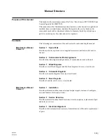
Purpose of this manual
This manual is the maintenance manual for Color Video Camera BVP-900/900P and
Camera Upgrade Unit BKP-7090.
This manual describes the information items necessary when the unit is supplied and
installed, items on maintenance, and items that premise the service based on the
components parts such as alignment, schematic diagrams, board layouts and spare
parts list, assuming use of system and service engineers.
Contents
This followings are summaries of the each section for understanding the manual.
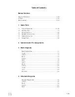
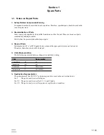
Section 1
Spare Parts
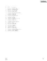
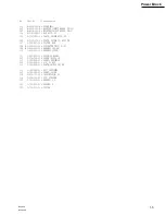
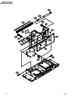
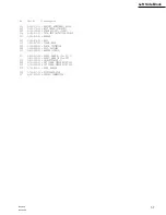
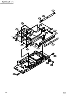
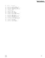
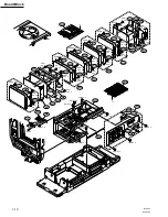
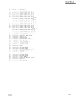
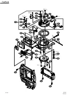
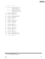
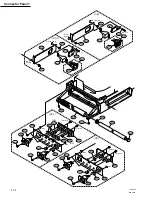
Describes parts list, exploded views, supplied accessories and fixtures list used in
the unit.
Section 2
Semiconductor Pin Assignments
Describes function diagrams and pin names of semiconductor used in the unit.
Section 3
Block Diagrams
Describes overall block diagram and the block diagrams for every circuit board.
Section 4
Schematic Diagrams
Describes schematic diagrams for every circuit board.
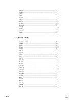
Section 5
Board Layouts
Describes board layouts for every circuit board.
Section 1
Installation
Describes information about connector input/output signals, instance of configura-
tion and function of internal switches.
Section 2
Service Overview
Describes information about board locations, circuit description, replacement of part
and notes on services.
Section 3
Electrical Alignment
Describes electrical adjustment necessary for maintenance of the unit or replacement
of parts.
Maintenance Manual
Volume 2
Maintenance Manual
Volume 1
Summary of Contents for BVP-900 Series
Page 4: ......
Page 30: ......
Page 36: ......
Page 160: ......
Page 167: ......
Page 181: ......
Page 193: ......
Page 224: ......
Page 272: ......
Page 275: ......
Page 278: ......
Page 282: ......
Page 363: ......
Page 384: ......
Page 396: ......
Page 404: ......
Page 408: ......
Page 411: ......
Page 412: ......
Page 414: ......
Page 454: ......
Page 455: ......
Page 479: ......
Page 480: ......
Page 482: ......
Page 498: ......
Page 519: ......
Page 520: ......

