2-4 (E)
BVP-900 P1
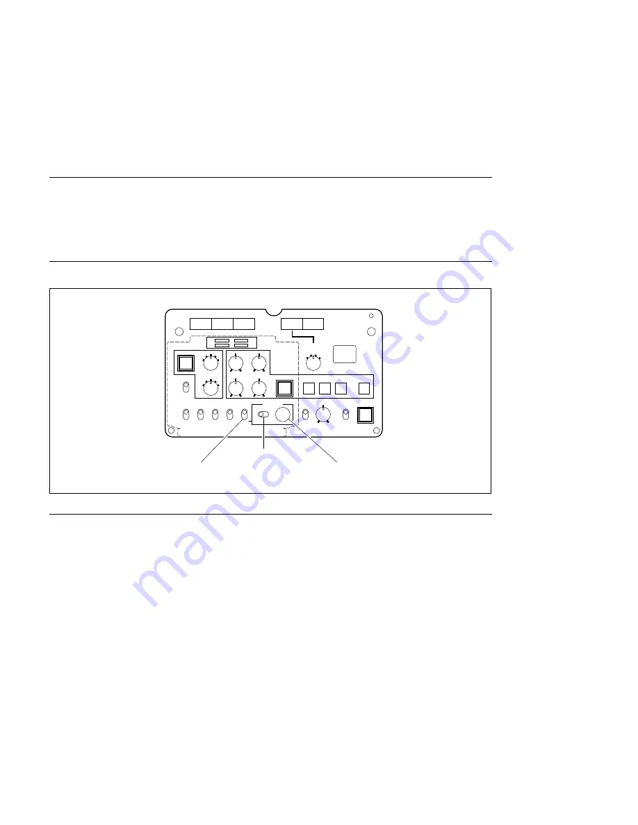
DISPLAY switch
MENU SELECT control
MENU SELECT switch
2
RET
RET 1
B
R
G
POWER
FILTER LOCAL
CENTER
MARKER
ON
SAFETY
ZONE
ON
DISPLAY
ON
WIDTH
HEIGHT
V-POSI
H-POSI
STORE
CURSOR
1
2
3
ON
CALL
ND
CC
OFF
OFF
OFF
OFF
OFF
MENU
CANCEL
ENTER
A
B
C D
E
1
2
3
4
5
MENU SELECT
1
2
3
4
POSITION
OFF
MENU
ON
OFF
VF DETAIL
Pin P
MIX VF
ON
UP TALLY
ON
RETURN
SELECT
2-4. Self-Diagnosis
2-4. Self-Diagnosis
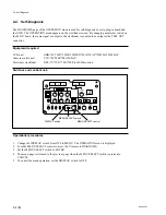
The DIAGNOSIS page of the OPERATION menu is used for self-diagnosis of every plug-in board and
the OHB. The OPERATION menu appears on the viewfinder screen. By changing an internal switch on
the MS-57 board, the same signal as output to the viewfinder is enabled to be output at the TEST OUT
connector.
Equipment required
CCD unit
OHB-730/730P/730WS/730WSP/750A/750AP/750WSA/750WSAP
Camera control unit
CCU-700/700P/700A/700AP
Electronic viewfinder
BVF-77/77CE/7700/7700P (or B/W monitor)
Switches and control knob
Operational procedures
1.
Change the DISPLAY switch from OFF to MENU. The OPERATION menu is displayed.
2.
Turn the MENU SELECT control to move the
→
cursor to DIAGNOSIS.
3.
Set the MENU SELECT switch to ENTER.
4.
The menu page is returned to the previous page when the MENU SELECT switch is pressed to
CANCEL.
5.
To cancel the menu operation, set the DISPLAY switch to OFF.
Summary of Contents for BVP-900 Series
Page 4: ......
Page 30: ......
Page 36: ......
Page 160: ......
Page 167: ......
Page 181: ......
Page 193: ......
Page 224: ......
Page 272: ......
Page 275: ......
Page 278: ......
Page 282: ......
Page 363: ......
Page 384: ......
Page 396: ......
Page 404: ......
Page 408: ......
Page 411: ......
Page 412: ......
Page 414: ......
Page 454: ......
Page 455: ......
Page 479: ......
Page 480: ......
Page 482: ......
Page 498: ......
Page 519: ......
Page 520: ......

