1-7 (E)
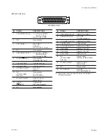
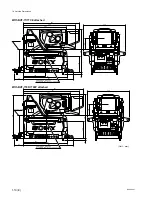
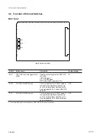
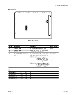
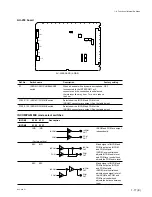
BVP-900 P1
*
3 Zi
>
10 k
Z
1: High impedance
0: 0
+
0.5 V
LENS ADRS A (Low-order bit)
LENS ADRS D (High-order bit)
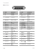
*
4 Zi
>
10 k
Z
1: High impedance
0: 0
±
0.5 V
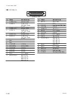
EX1
EX2
EX3
MODE
1
1
1
EXTENDER OFF
1
0
1
EXT-A (
x
1.5) ON
0
1
1
EXT-B (
x
2) ON
0
0
1
EXT-C (
x
2.5) ON
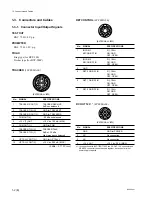
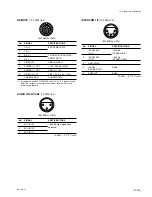
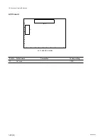
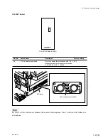
1-3-2. Connection Connector
Connection made with the connector panels during instal-
lation or service should be made with the connectors/
complete cable assemblies specified in the following list or
equivalent parts.
Connector name
Connection connectors/cables
TEST OUT
1-569-370-12 Plug, BNC
PROMPTER
(BNC)
TRACKER
1-506-522-11 Plug, 10P Male or
(10P FEMALE)
HIROSE HR10R-10P-10P equivalent
RET CONTROL
1-560-078-00 Plug, 6P Male or
(6P FEMALE)
HIROSE HR10-7PA-6P equivalent
DC OUT 12V
1-566-425-11 Plug, 4P Male or
(4P FEMALE)
HIROSE HR10A-7P-4P equivalent
REMOTE
1-766-848-11 Plug, 8P Male or
(8P FEMALE)
1-783-372-11 REMOTE cable
*
1
*
2
(Supplied with RM-B150, 10 m) or
CCA cable assembly (option)
CCA-5-10 (10 m)/CCA-5-3 (3 m)
*
2
AUDIO IN
1-508-084-00 XLR, 3P Male or
(3P FEMALE)
ITT Cannon XLR-3-12C equivalent
INTERCOM
1-508-370-11 XLR, 5P Male or
(5P FEMALE)
ITT Cannon XLR-5-12C equivalent
*
1: The use of REMOTE cable enables to monitor video signals.
*
2: If using a cable of length different from a standard product, contact your
local Sony Sales Office/Service Center.
1-3. Connectors and Cables
Summary of Contents for BVP-900 Series
Page 4: ......
Page 30: ......
Page 36: ......
Page 160: ......
Page 167: ......
Page 181: ......
Page 193: ......
Page 224: ......
Page 272: ......
Page 275: ......
Page 278: ......
Page 282: ......
Page 363: ......
Page 384: ......
Page 396: ......
Page 404: ......
Page 408: ......
Page 411: ......
Page 412: ......
Page 414: ......
Page 454: ......
Page 455: ......
Page 479: ......
Page 480: ......
Page 482: ......
Page 498: ......
Page 519: ......
Page 520: ......


