background image

S0 User Handbook

7

USER GUIDE

U S E R   G U I D E

2

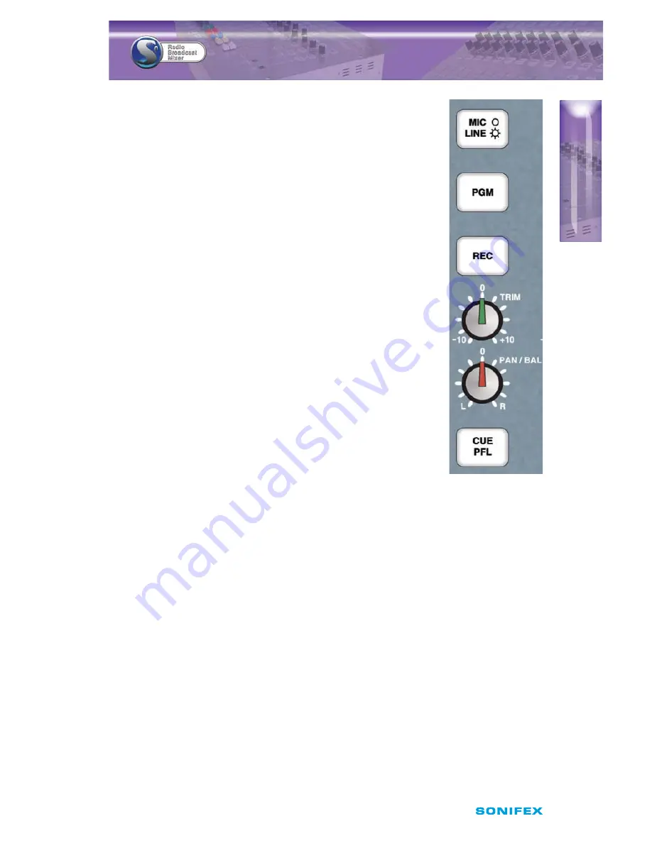
This button can be disabled so that the selected input cannot be 
changed. The button operation and phantom power settings are part 
of the Configuration Options.

PGM Button

This button allows the output of the channel to be mixed onto the 
Program Bus output. The button illuminates green to indicate the 
channel is active on the Program Bus. This button can be disabled via 
the Configuration Options, so that it is permanently on or off.

REC Button

This button allows the output of the channel to be mixed onto the 
Record bus output. The button illuminates red to indicate the channel 
is active on the Record Bus. This button can be disabled via the 
Configuration Options, so that it is permanently on or off.

TRIM Control

This control allows the level of the audio on this channel to be 
adjusted by ±15dB. This additional gain is applied prior to the channels 
fader, and is useful for setting relative levels between audio sources on 
different channels. 

Note:

 It is a good idea to set up all the audio channels so that they are 

all at the same reference level when the fader is fully up, meaning the 
mix levels are determined solely by the position of the faders.

PAN/BAL Control

This control has two functions depending on whether MIC or LINE is 
selected.

In MIC mode the control acts as PAN and allows the mono input to be positioned in the 
stereo image. With the control in the centre position, the signal is present on both the left 
and right channels. Turning the control fully anti-clockwise pans the signal to the left by 
increasing the level by 3dB and the signal on the right channel is turned off. Turning the 
control fully clockwise pans the signal to the right by increasing the level by 3dB. The signal 
on the left channel is turned off. 

In LINE mode the control acts as BAL (balance) and is used to alter the stereo image of the 
stereo input. With the control in the centre position, the signal is un-altered. Turning the 
control fully anti-clockwise shifts the signal to the left by increasing the gain by 6dB and 
the signal on the right channel is reduced by 6dB. Turning the control fully clockwise shifts 
the signal to the right by increasing the gain by 6dB while the signal on the left channel is 
reduced by 6dB.

CUE PFL Button

Selecting CUE PFL routes the pre-fader input signal to the monitoring section where the 
signal can be heard on the Monitor, Presenter or Guest headphones (provided that the 
associated AUTO CUE/PFL button is selected). The level can then be checked on the meters 

Fig 2-3: Mic/Line 
Channel Strip.

Summary of Contents for S0

Page 1: ...S0 Radio Broadcast Mixer User Handbook...

Page 2: ...or any loss or damage whatsoever arising form the use of information or any error contained in this manual No part of this manual may be reproduced or transmitted in any form or by any means electroni...

Page 3: ...ngs 5 Installation Notes 5 Atmosphere 5 Electromagnetic Radiation 5 Dimensions and Cut Out Size for Flush Mounting 5 User Guide 6 S0 Input Channels 6 Channels 1 4 Mono Balanced Mic Stereo Unbalanced L...

Page 4: ...Button 18 Presenter SPLIT CUE PFL Button 18 PRESENTER Headphones 18 Guest AUTO CUE PFL Button 18 Guest TALKBACK Button 18 GUEST Headphones 18 Using the Telephone Interface 19 Making A Telephone Call...

Page 5: ...S0 User Handbook e CO NT E N TS CONTENTS W Connectors and Cabling 30 XLR 3 Pin Connectors 30 RCA Phono Connectors 30 6 35mm A Gauge Stereo Jack Plugs 30 Technical Specification For S0 32...

Page 6: ...UE PFL Fader LINE HOLD Button 13 Fig 2 12 Mains Outputs 14 Fig 2 13 MONITOR I O USB 15 Fig 2 14 LED Meter Display 16 Fig 2 15 PGM REC and EXT 1 Buttons 16 Fig 2 16 Monitor Presenter and Guests Control...

Page 7: ...al recommendations iii the Goods are returned to the Company s premises at the Purchaser s expense iv any Goods or parts of Goods replaced shall become the property of the Company v no work whatsoever...

Page 8: ...the best of the belief and knowledge of the Company and the Company accepts no liability in respect of its accuracy beyond that set out in Condition a f Subject to Condition e no representation condi...

Page 9: ...d and return it to Sonifex Ltd in the UK or register online at www sonifex co uk register For your own records you should write down the serial number of the S0 Mixer S0 Mixer Serial Number Unpacking...

Page 10: ...upplied with a single fuse in the live conducting path of the power in feed at the power supply For reasons of safety it is important that the correct rating and type of fuse is used Incorrectly rated...

Page 11: ...rrently used in EEE manufacture including lead mercury cadmium hexavalent chromium and halide containing compounds PBB polybrominated biphenyl and PBDE polybrominated diphenyl ether Elimination of the...

Page 12: ...61 Station Road Position Irthlingborough Company Northants Address NN9 5QE UK Tel 44 0 1933 650 700 Tel Fax 44 0 1933 650 726 Fax Email technical support sonifex co uk Email For the Serial No of your...

Page 13: ...g telephone calls and a 3 5mm stereo jack for plugging in an mp3 player The addition of a USB port allows for recording to a PC and for playing a PC automation system directly through the mixer The he...

Page 14: ...PS NJTDFMMBOFPVT TPVSDFT TVDI BT 1 QMBZFST t OEFQFOEFOU 1SPHSBN BOE 3FDPSE CVT PVUQVUT t 1SF BEF JTUFO BWBJMBCMF PO BMM DIBOOFMT t 76 BOE 11 NFUFSJOH PO B MBSHF EJTQMBZ t VJME JO IFBEQIPOF WPMVNF MJNJ...

Page 15: ...for the pre amp Input channel 1 also serves as the microphone input for a dedicated talkback channel The stereo RCA phono line inputs on channels 1 to 8 have 10dB of gain at the input to compensate f...

Page 16: ...eadphone outputs from either PGM REC or from an additional unbalanced stereo RCA phono input EXT 1 This external input can be used for monitoring an off air signal or studio output Green illuminated A...

Page 17: ...id installing it in atmospheric conditions which are dusty smoky or dirty or where there is moisture or vibration Do not use any liquids to clean the fascia of the mixer a soft dry brush is ideal Use...

Page 18: ...e microphone input which is applied prior to the channels TRIM control The available gain range is from 24dB to 65dB ref 50dBu input and allows a wide range of microphone types to be used LINE INPUT T...

Page 19: ...ion of the faders PAN BAL Control This control has two functions depending on whether MIC or LINE is selected In MIC mode the control acts as PAN and allows the mono input to be positioned in the ster...

Page 20: ...ed The channel is routed to the PGM or REC bus the fader is closed and the remote stop output is enabled Illuminated Green The channel is routed to the PGM or REC bus the fader is open and the remote...

Page 21: ...anges the channel selection between the two LINE inputs INP1 corresponds to the lower numbered line input i e on channel 5 INP1 is line 5 1 and INP2 corresponds to the higher numbered line input i e o...

Page 22: ...ader input signal to the monitoring section where the signal can be heard on the Monitor Presenter or Guest headphones provided that the associated AUTO CUE PFL button is selected The level can then b...

Page 23: ...ndependently depending on the Configuration Options chosen R BAL and C BAL Controls These small multi turn screw adjusters are used to tune the telephone interface to the characteristics of a standard...

Page 24: ...er and is useful for setting relative levels between audio sources on different channels Note It is a good idea to set up all the audio channels so that they are all at the same reference level when t...

Page 25: ...e 100mm VCA fader is a linear level control that operates between fully attenuated in its lowest position to unity gain when fully open LINE HOLD Button This button has a different function depending...

Page 26: ...a momentary pulse for 0 5 seconds If the fader is closed the remote stop will become active and give a momentary pulse for 0 5 seconds This is the default operation when in AUX mode but this can be ch...

Page 27: ...ti turn screw adjuster sets the maximum audio level of the signal fed to the presenter and guest headphones It is designed to protect the headphone users from excessive audio levels Once the audio lev...

Page 28: ...ale indicates a 4 dB change in signal level The VU meter operates between 20 and 3 volume units and follows the standard definition for a VU meter A red LED indicates which scale is currently selected...

Page 29: ...e replaced if one or more input channels have CUE PFL selected The channels with CUE PFL selected will be mixed and fed to this output without having to have the fader open This button illuminates gre...

Page 30: ...n is selected and it illuminates amber when selected PRESENTER Headphones This stereo 6 35mm socket is the feed to the presenter headphones It is wired in parallel with the presenter headphone connect...

Page 31: ...automatically activate the LINE HOLD button which will connect the call to the S0 The presenter can talk to the person on the telephone via microphone channel 1 and listen on the headphones but the au...

Page 32: ...UFE B CVUUPO XPVME SFQFBUFEMZ BTI UJNFT XJUI B TIPSU QBVTF CFUXFFO FBDI TFRVFODF PG BTIFT To Enter Setup Mode 1 Ensure all faders are closed 2 Press and hold the Monitor Presenter and Guest AUTO CUE P...

Page 33: ...channel 5 INP2 is LINE 5 2 Mode 1 INP1 INP2 inputs available for selection default for channels 5 7 Mode 2 INP1 input only the button is disabled Mode 3 INP2 input only the button is disabled Mode 4...

Page 34: ...channels 1 9 and can be activated on a per channel basis Mode 1 PGM is selectable default Mode 2 PGM is always on the button is disabled Mode 3 PGM is always off the button is disabled REC Button Mod...

Page 35: ...tivated by pressing the START button Momentary remote stop for 0 5 seconds when the channel becomes inactive Mode 3 Momentary remote start for 0 5 seconds when the channel becomes active Repeat start...

Page 36: ...e S0 is connected for the first time Using SCi For The First Time Once the S0 Mixer is connected to the computer launch the SCi program The first thing to appear is the SCi Launcher which shows a list...

Page 37: ...guration and Info Updates The bottom of the main screen shows the product and version information of the connected unit Fig 3 2 SCI Channel Configuration Screen The first tab shows the Channel Configu...

Page 38: ...the USB Audio input channel is automatically routed to the monitor section If enabled the USB Audio input will be available on any of the monitor channels that have the AUTO CUE PFL function enabled T...

Page 39: ...and then press the Save Configuration button A save dialog will be displayed allowing the filename to be entered Upon pressing the save button the current settings will be stored in the selected file...

Page 40: ...e S0 will automatically reboot and SCi will reconnect and show the new firmware version number The S0 is designed to power up in the same state it was in when power was removed It is possible to clear...

Page 41: ...B Audio output is encoded from the audio signal on the PGM bus This involves changing 2 jumper settings that are located on the PCB directly under the front panel on the S0 Contact Sonifex Technical S...

Page 42: ...utputs Pin 2 Hot In Phase Signal Pin 1 Ground Screen Signal Pin 3 Cold Out Of Phase Signal 3 Pin Socket Female 3 Pin Socket Male Pin 2 Hot In Phase Signal Pin 1 Ground Screen Signal Pin 3 Cold Out Of...

Page 43: ...or Output Sleeve Ground Screen Signal Fig 5 4 6 35mm inch A Gauge Stereo Jack Plugs used for Remote Outputs This connector type is also used on the Light Control Output Tip Normally Open Switch to Sle...

Page 44: ...dance 20k electronically unbalanced Input Gain Range 10dB ref 0dBu at PGM output TRIM pot 15dB Frequency Response 20Hz to 20kHz 0 5dB 0dB Noise 20Hz 20kHz 92dBu ref 0dB fader down no routing Total Har...

Page 45: ...1 4 stereo jack socket for light control Telephone 2 x RJ11 6 4 1 x line 1 x handset USB Audio 1 x Type B receptacle USB Serial 1 x Type B receptacle Mains Input Filtered IEC continuously rated 85 264...

Page 46: ...34 S0 User Handbook NOTES N OT E S...

Page 47: ...S0 User Handbook 35 N OT E S NOTES...

Page 48: ...w w w sonifex co uk t 44 0 1933 650 700 f 44 0 1933 650 726 sales sonifex co uk...

Reviews: