


44
thermostat).
Note:
the remote control is usually accompanied by a manual. To use the
remote control, you must install an interface (Figure 27
–b).
a) b)
Figure 27
– Remote control (programmable thermostat) and connection interface – both not
included.
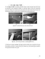
For
wireless
remote controls, both wires must be connected, as indicated in the
following figure:
a)
b)
Figure 28
– Connection of the wireless remote control
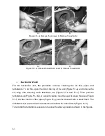
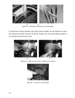
For the
wired
remote control, the black and grey wires must be connected to the
receiver as shown in the following figure.
Colour codes:
Gr
– grey
B
– black
Br
– brown
Bl - blue
Summary of Contents for Alpes 10 kW
Page 22: ...19 b c Figure 17 Examples of standard installations ...
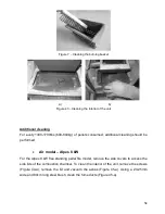
Page 52: ...49 b c d e f g Figure 33 Installation of the UPS kit ...
Page 61: ...58 a b c d e f ...
Page 70: ...67 13 5 Symbols Figure 60 Symbols ...
Page 71: ...68 14 Electrical diagram of the Free Standing Pellet Fire unit Figure 61 Electrical diagram ...
Page 78: ...75 ...


