Solidscape 3Z Max User Manual Download Page 21


Power on Procedure 


CAUTION:


If the unit has been exposed to cold weather for an extended 

period of time, i.e., below freezing temperatures for twelve hours 
or longer, allow the unit to warm up to room temperature prior to 
startup. A minimum warm up period of twelve hours is 
recommended.


1.  Turn on the vacuum power switch if it is not already set to the on position. 
2.  Close the 3Z Series unit side and top covers.   

Note: 

Both covers must be closed or the interlock will prevent the system from 
completing the start up sequence. 

3.  Turn on the 3Z Series system by pressing the ‘I’, side of the power switch on the left rear 

corner of the unit.  

4.  Observe the following start up screen, See Figure 2-1, as the system progresses through 

the initialization stages. Be patient during power-on initialization.  Note that it takes 
approximately one minute to start up the system and during most of that time the unit 
appears idle.  


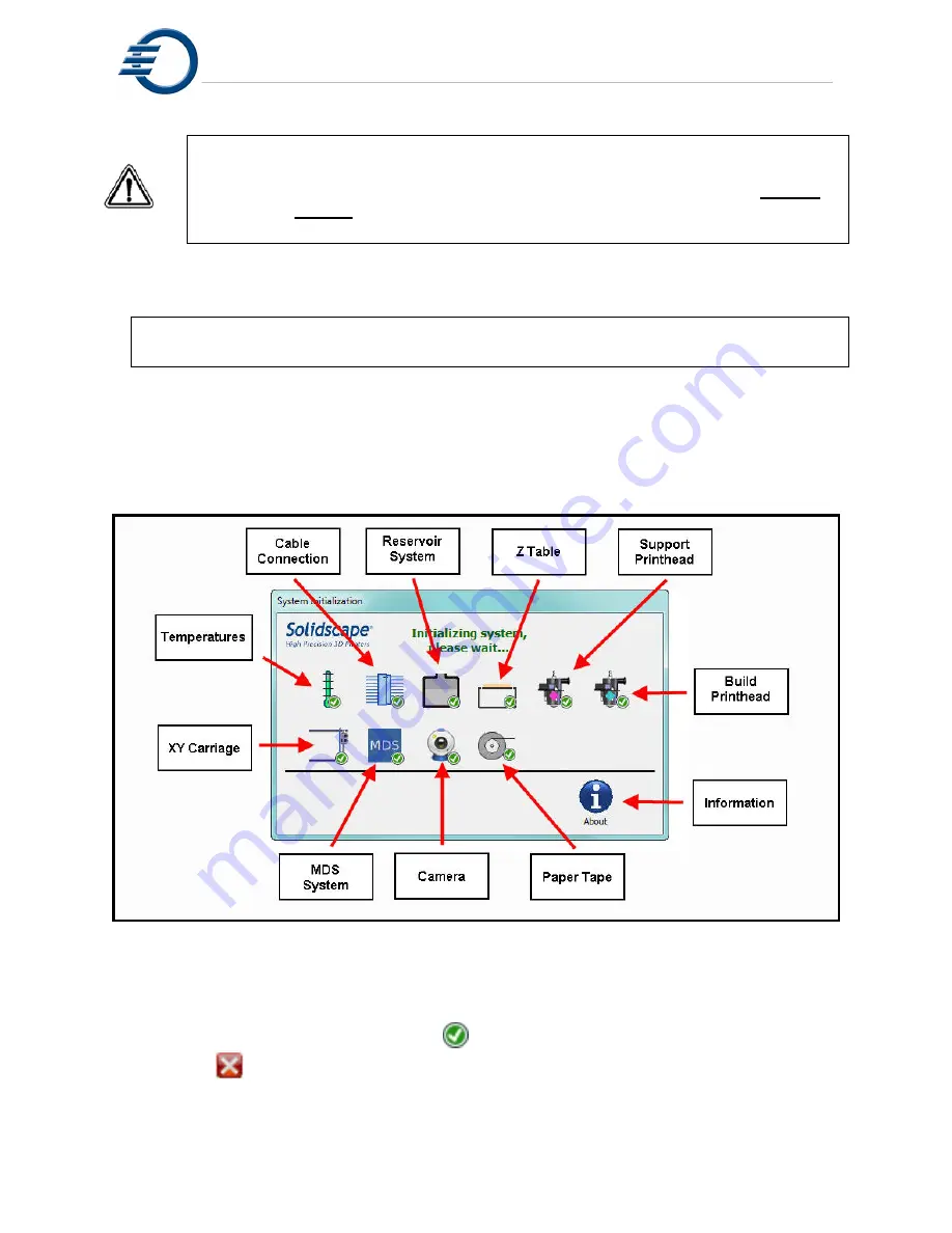
Figure 2-1  Initialization screen  

5.  All of the initialization screens are automatic and progress from one to the next without any 

operator intervention required. The icon for each process will be

 grey 

during initialization. 

The icon will  display a green check 

mark upon successful completion  


or a red                 

if the process is incomplete or is failing.  Figure 2-2. illustrates that the 

 
       camera did not initialize properly. If an initialization fails, touch the failing icon for a more 
       detailed explanation. 

Summary of Contents for 3Z Max

Page 1: ...I 3zseries User Manual Part Number 840180 Rev F August 2013...

Page 2: ...registered trademarks of Solidscape Inc is a registered trademark of Solidscape Inc BIOACT is a registered trademark of Petroferm Inc Windows is a registered trademark of Microsoft Corporation in the...

Page 3: ...o frequency energy and if not installed and used in accordance with the instruction manual may cause harmful interference to radio communications Operation of this equipment in a residential area is l...

Page 4: ...elivering the Product to an authorized Solidscape warranty center A dated proof of purchase from Solidscape or an authorized Solidscape dealer must accompany the claim The customer will ship the repla...

Page 5: ...VI...

Page 6: ...SETUP 11 3 1 1 Build Plate Mounting 12 3 1 2 Build Plate Barcode 13 3 2 CLEANING THE CUTTER 14 3 3 FILE TRANSFER AND REMOVAL 15 3 3 1 File Transfer via Flash drive 15 3 3 2 File Transfer via Network...

Page 7: ...O YOUR PC 41 10 1 INTERFACE OVERVIEW 41 10 2 WIRED CONNECTION VIA DHCP 41 10 3 WIRED CONNECTION VIA STATIC IP ADDRESS 42 10 4 WIRED CONNECTION PEER TO PEER 42 10 5 WIRELESS VIA DHCP 43 10 6 ASSIGNING...

Page 8: ...dding Material 23 Figure 6 4 Entering Barcode Manually 24 Figure 6 5 Barcode Missing 24 Figure 7 1 Printhead Screens 26 Figure 7 2 Printhead Ready Not Ready 27 Figure 7 3 Detailed Printhead Maintenanc...

Page 9: ...Panel 49 Figure 10 11 Windows 7 Network and Sharing Center 50 Figure 10 12 Windows 7 Network Connections 50 Figure 10 13 Starting Windows XP Control Panel 51 Figure 10 14 Windows XP Control Panel 52...

Page 10: ...result from failure to read and comply with the safety instructions CAUTION Flammability cautions are further distinguished by the FLAMMABLE accompanying international Flammable symbol and are printe...

Page 11: ...cross the build region Anything in the vicinity of the cutter blade is at risk of injury or damage Confirm that the interlock system is engaged and prohibits cutter motor activation prior to working i...

Page 12: ...e unopened materials in their original containers in a cool dry place and out of direct sunlight CAUTION The use of any materials other than new materials provided by Solidscape voids the system warra...

Page 13: ...Cautions XIV...

Page 14: ...ystem The primary steps of model making with a 3Z Series consist of Selecting one or more model files and from them preparing a model making job file at the operator s workstation Transferring the job...

Page 15: ...cators 1 2 Touch Panel Operator input to a 3Z Series printer is provided through a touch screen The printer provides feedback to the operator via the front panel display 3Z Touch remote runs on any re...

Page 16: ...and the printer Ready Status indicator The icons below the black line are used for initiating commands to the printer Figure 1 4 3Z Touch Panel The Ready Status Indicator shows the general status of...

Page 17: ...b Complete Printer has completed the job and the cover has opened 6 Auto Recovery The printer is recovering from an abnormal operation 7 Intervention The printer has paused and is waiting for assistan...

Page 18: ...kstation and the 3Z Printer The program is started and then runs invisibly in the background When an STL SLC file or a folder with numerous files are dragged copied into the 3Z Organizer Queue folder...

Page 19: ...he system This tool is valuable for observing features searching for potential defects and identifying anomalies from the 3D CAD process that appear to represent a unified solid model but in fact have...

Page 20: ...hrough Step 7 of this procedure must also be performed after the vacuum filter has been replaced All references to the unit refer to the actual 3Z Series printer 1 Confirm that the unit is powered off...

Page 21: ...the left rear corner of the unit 4 Observe the following start up screen See Figure 2 1 as the system progresses through the initialization stages Be patient during power on initialization Note that i...

Page 22: ...he last layer of the job will be cut back and the job will automatically be continued from that point This automatic restart function is particularly valuable following power interruptions when no one...

Page 23: ...Power on Procedure 10...

Page 24: ...any Icon for additional information Figure 3 1 Printer Idle Not Ready 3 1 3Z Base Setup The system builds composite models by depositing build and support material on a removable build plate The build...

Page 25: ...on the build table See Figure 3 3 Build Plate Mounting 6 Ensure that the build plate lies flat on the build table at all four corners If not debris may be caught between the table and plate Remove the...

Page 26: ...print a series of dots and lines on the surface and then use these dots and lines to cut the new plate to the proper height The printer will then remember this information for future print jobs If th...

Page 27: ...ris from the blade To clean the cutter first unlock the 2 locking clips and open the cutter shroud to reveal the cutter blade See Figure 3 4 Opening Cutter Shroud Figure 3 5 Opening Cutter Shroud 2 Ca...

Page 28: ...en the paper tape roll and the vacuum hose See Figure 3 7 USB Port Location 3 The printer will recognize and download the most recently created file automatically only if there is no job already loade...

Page 29: ...h Drive P N 945087 3 3 3 Removing a file 1 From the System Idle screen select More 2 Select Clear Job 3 4 Starting the Print Job 1 In the System Idle menu insure all icons have a green check next to t...

Page 30: ...4 1 Pausing the Job At any time you can select Pause Job to interrupt the printing by touching the Pause icon See figure 4 2 Job Paused The carriage will return to the park position While the printer...

Page 31: ...want to terminate the print job select the Terminate icon At this point the printer will ask you to verify the termination of the print job Touch Yes to verify or No to return to the pause menu See Fi...

Page 32: ...the Finish flag See Figure 5 1 Job Waiting for Finalize Touching the Finalize icon will raise the table open the cover and the current job file will be removed from the printer See Figure 5 2 Job Fin...

Page 33: ...Job Finish 20...

Page 34: ...hange to a yellow Warning state At this time the paper tape roll should be changed as soon as possible If the printer is running pause the job and open the top and right side covers before proceeding...

Page 35: ...en 4 and 5 crayons for each material The crayons are supplied in a box of 10 The box will also contain 10 peel and stick bar code strips used to verify that the material was manufactured by Solidscape...

Page 36: ...A B C A Remove a barcode label from the barcode sheet B Place the label on the paper tape within the printed rectangle C Remove the tank cap and add 1 crayon D Replace the tank cap and close the cove...

Page 37: ...e the printer will routinely prompt the user to enter a valid barcode See Figure 6 5 Barcode Missing A barcode should be entered as soon as possible The printer must be Idle and the cover closed to en...

Page 38: ...ed whenever a new job is started There are 2 dialog boxes associated with printhead maintenance One indicates the status of the printhead and allows the user to initiate automated maintenance commands...

Page 39: ...Maintenance and Printer Status 26 Figure 7 1 Printhead Screens...

Page 40: ...te These include purging firing wiping and testing the printhead The Replace icon is used whenever a new printhead is installed The printer will automatically prepare the new printhead for operation T...

Page 41: ...operating hours It also allows the operator to perform specific commands and tests on the printhead See Figure 7 3 Detailed Printhead Maintenance Any of the printhead commands can be immediately inter...

Page 42: ...ercise the printhead with a series of frequency tests Wipe Touching the Wipe icon will command the printer to wipe any excess material from the face of the printhead 7 2 Cleaning the Camera Lens The 3...

Page 43: ...r Status 30 the remaining debris removed with a Qtip moistened with Isopropyl alcohol See Figure 7 6 Cleaning the Purge Cap Removal Station Figure 7 5 Cleaning Camera Lens Figure 7 6 Cleaning the Purg...

Page 44: ...aside First move the printhead carriage away from the MDS sensor Next move the paper tape by rotating the paper tape roll clockwise and feeding the paper up through the spring clip Refer to Figure 6 1...

Page 45: ...f gears to advance the paper These gears should be checked periodically for debris It is important to keep these gears clean To clean the assembly first open the right side door to access the paper ta...

Page 46: ...that allow the user to gather information from and Initiate commands to various sub systems within the printer These sub systems are accessed from the System Idle screens by touching the More and Back...

Page 47: ...heck next to the icon See Figure 8 2 Temperature Information Note Values may be different Figure 8 2 Temperature Information 8 2 2 Printhead Maintenance Refer to Section 7 1 Printhead Maintenance 8 2...

Page 48: ...hing the individual icons will allow the user to move the table up or down a specific amount or move the table to the up most position The user can also perform a foam cut of the 3Z Base Each time the...

Page 49: ...the acceptable values Figure 8 5 Job Information Figure 8 5 Job Information 8 2 6 Standby When the Standby icon is touched the printer will reduce the temperatures of the printheads heated lines and...

Page 50: ...ed to verify that the printer has the correct software and firmware revisions installed See Figure 8 6 About Printer Information Figure 8 6 About Printer Information 8 2 8 MDS Touching the MDS icon wi...

Page 51: ...Printer Subordinate Systems 38...

Page 52: ...he fan and touch again to remove power from the fan Touching the Home icon will initiate a series of commands to set the home position for the X Y carriage These commands assist in verifying that the...

Page 53: ...ter assembly Then the cutter assembly will be engaged with the carriage The carriage will then move the cutter assembly back and forth in the X motion direction 2 times Then the cutter assembly will b...

Page 54: ...ucing any concerns about privacy Having your 3Z series printer connected to the internet will also help us to keep you current with software updates This will help ensure that you are always running t...

Page 55: ...inserted into an available port on the network router To assign the IP address for your 3Z Series printer follow the directions in the Assigning a Static IP Address to a 3Z Printer section of this do...

Page 56: ...you will need a third party wireless Ethernet adapter The wireless Ethernet adapter must connect to the 3Z Series printer Ethernet port wireless USB adapters will not work on the 3Z Series printers Th...

Page 57: ...f the 3Z Series printer Plug in the wireless Ethernet adapters power supply The wireless Ethernet adapter should connect to your wireless network and supply an IP address to the 3Z Series printer See...

Page 58: ...Connecting the Printer 45 Figure 10 5 Stylus and Touch Screen Touch the button and select Settings Control Panel From the Control Panel double click Network and Dial Up Connections See Figure 10 6...

Page 59: ...windows for the network adapter Open the status bar again and click the icon and click the icon this will open the virtual keyboard Figure 10 7 DM9CE1 Icon Click the radio button labeled Specify an IP...

Page 60: ...ut any open windows by pressing the icon for that window Power the machine off and back on The network connection icon in the status bar should change from to This signifies that the machine is connec...

Page 61: ...Connecting the Printer 48 Figure 10 9 Starting Windows 7 Control Panel...

Page 62: ...Connecting the Printer 49 Figure 10 10 Windows 7 Control Panel In the Network and Sharing Center click the Change adapter settings link This will open the Network Connections window...

Page 63: ...the Local Area Connection icon and select Properties this will open the Local Area Connection Properties window In the Local Area Connection Properties window select Internet Protocol Version 4 TCP IP...

Page 64: ...ow Click the button to close the Local Area Connection Properties window Close any windows that are still open and reboot the PC 10 8 Windows XP Static IP Address Assignment Click on the Windows XP St...

Page 65: ...t Internet Protocol TCP IP and click the button This will open the Internet Protocol TCP IP Properties window In the Internet Protocol TCP IP Properties window use the radio button to select Use the f...

Page 66: ...Connecting the Printer 53 Figure 10 15 Windows XP Network Connection Properties...

Page 67: ...Connecting the Printer 54...

Page 68: ...s Temperature resistant gloves or mitts 11 1 2 Required Tools Heater Stirrer Device capable of maintaining temperature between 50 C 55 C Temperature Measuring Device capable of 2o C Pyrex temp resista...

Page 69: ...Base CAUTION The Heater Stirrer gets hot Wear gloves or use caution when HOT removing the model CAUTION Do not use force to remove the model 1 Remove any loose dust or debris from the model that is ab...

Page 70: ...when heated in the solvent To prevent this from occurring remove some of the support material with a pointed knife or drill bit prior to immersion in the solvent bath By creating a hollow in the supp...

Page 71: ...mall tweezers are a good tool for this 9 Turnoff the Heater Stirrer device unless you have additional models to de wax 10 At this time the models can be cleaned using soft bristled brushes and or comp...

Page 72: ...ckness used Crisp edges corners and round surfaces Shiny finish on all surfaces only thin layer models Clean finish on all sides not uneven on verticals 2 If the model does not meet one of the precedi...

Page 73: ...Post Processing 60...

Page 74: ...heck Replace Build Plate Check Replace Vacuum Bag Replace Replace Camera Lens Clean Clean Paper Tape Drive Area Clean Clean Entire Unit Clean Belts Inspect Replace Rails Clean Cutter Blade Inspect Cle...

Page 75: ...ed Voltage Current 100 240 VAC 5 Amps Fuse 5 Amp Slow Blow T 250V Certifications CE Certified TUV FCC Class A Unattended Operation 72 hours max Reservoirs Level Accuracy 5 Capacity max 5 crayons 150 m...

Page 76: ...3 F 95 C to 230 F 110 C Density 1 25 g ml Melting Shrinkage 65 solid to liquid No residue after autoclave process No shrinkage distortion disintegration No toxins 3Z Support Material Composition Natur...

Page 77: ...Technical Specifications 64...

Page 78: ...to the vacuum switch box and facilitates 3Z Series control over the vacuum Vacuum bags A starter supply of vacuum bags capable of filtering particles as small as 1 micron Vacuum bag part numbers Elect...

Page 79: ...ss than 60 dBA or at least quiet enough for your environment High reliability and long life under nearly continuous operation Should your 3Z printer come without a vacuum or you need to replace an old...

Page 80: ...reuse the vacuum bag Never operate the vacuum without a vacuum bag Never permit the vacuum bag to become more than one half full Never permit dust to enter the vacuum motor Operating the vacuum witho...

Reviews: