


SOLID AIR ®
CLIMATE SOLUTIONS
•
T +31 598 36 12 21
•
www.solid-air.com
•
37
- 58
Product overview
Technical data
Ordering key
Installations
Accessories
Replacements
Maintenance and operation
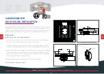
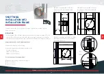
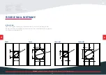
The wall is composed of 1 x 2 plasterboard boards, 20 mm thick, installed on a steel
frame construction.
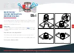
SHAFT WALL
INSTALLATION MF2
INSTALLATION FRAME
INSTALLATION
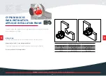
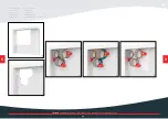
1. For fire dampers Ø d < 625 mm, make a steel subframe according to drawing (1). For fire
dampers Ø d > 625 mm, make a steel subframe according to drawing (2). For installa-
tion in shaft walls without metal studs, make a steel subframe according to drawing (3).
Damper blade must be closed during installation!
2. Place the fire damper in the opening.
3. Insert fire damper into wall and fasten with screws
(12 pcs 6 x 160 mm).
FDC25: 4 pcs 6 x 160 mm
FDC40: 12 pcs 6 x 160 mm
Test the operation of the damper blade!
*Dimension G depending of the damper type is:
FDC 25 G = 10 mm
FDC 40 G = 25 mm
< 2000 mm
d+G
d+G
Ø(d+G)
103
(90)
200
20 20 20 20
50
103
20 20
50
50
FDC25
FDC40
FDC-MF2 Fire damper installation in 90 mm
shaft wall without metal studs (maximum
wall width 2000 mm).
625 mm
Ø(d+G)
d+G
d+G
625 mm
d+G
Ø(d+G)
CW50 profile
UW50 profile
FDC-MF2 Fire damper (Ø d < 625 mm)
installation in 90 mm shaft wall with
metal studs.
FDC-MF2 Fire damper (Ø d > 625 mm)
installation in 90 mm shaft wall with
metal studs.
1
2
3
>
>


