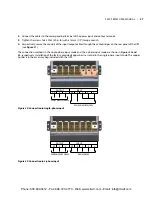
Configuring the Bypass Voltage
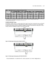
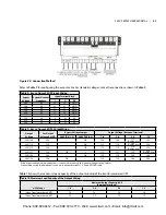
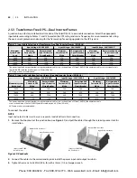
The UPS bypass voltage is factory-set and the copper busbar jumper has been factory-installed� If the jumper setting does
not match the input source, the bypass voltage jumper may need to be changed to ensure the correct output voltages
are provided when operating in bypass mode� Refer to
Table 9
for the proper setting location according to the AC mains
voltage available and to
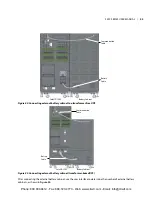
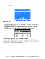
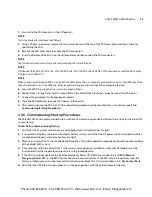
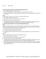
Figures 34
and
35
for the jumper setting location�
Figure 34: Setting bypass voltage jumper (default: 208VAC)
Figure 35: Setting bypass voltage jumper (200/220/230/240VAC)
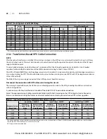
Table 7: Input cable selection for transformer-based frames (50 Hz)
Maximum System
Rated Load
Input Voltage - 220VAC
Input Voltage - 230VAC
Input Voltage - 240VAC
Maximum
Current in UPS
Mode
Recommended
Input Protection
Circuit Breaker
Maximum
Current in UPS
Mode
Recommended
Input Protection
Circuit Breaker
Maximum
Current in UPS
Mode
Recommended
Input Protection
Circuit Breaker
5kVA
25A
50A
24A
50A
23A
50A
10kVA
49A
63A
47A
63A
45A
63A
15kVA
73A
100A
70A
100A
67A
100A
20kVA
97A
125A
93A
125A
90A
125A
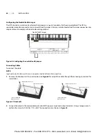
The power input and output terminals accept a maximum cable cross-sectional area of is 70mm2 (2/0AWG); the minimum cable
cross-sectional area is 16mm2 (6AWG)� The rated torque is 12�43Nm (110 in-lb)�
90°C copper wire recommended�
Jumper
1
2
Jumper
1
2
S5KC SERIES USER MANUAL | 29
Phone: 800.894.0412 - Fax: 888.723.4773 - Web: www.clrwtr.com - Email: [email protected]

