

20
ITYS PRO
10-15-20 kVA - Ref.: IOMITYPRXX00-EN 03
6-1
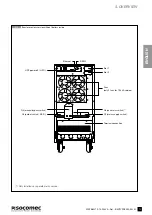
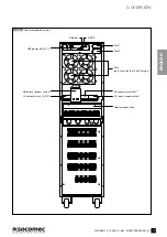
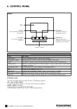
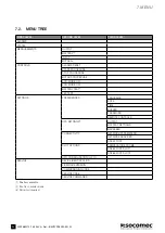
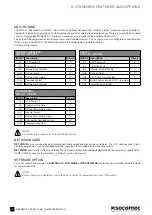
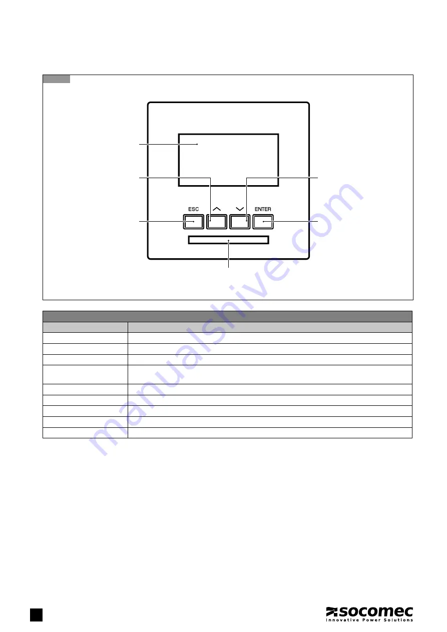
6. CONTROL PANEL
ESC button
Exits current page, aborts
operations
Luminous status bar
Display
UP button
Scrolls up through the available
menus/values
ENTER button
Accesses the currently
displayed menu, accepts/sends
confi gurations and commands
DOWN button
Scrolls down through the
available menus/values
Control panel with LED status bar indicator
Colour
Description
Flashing green
Start-up procedure in progress / Battery test in progress
Flashing green-yellow
Maintenance alert / An alarm is present with load supplied by the inverter
Yellow
On battery / Forced on bypass (with eco mode off) / Maintenance alert / Redundancy lost
Flashing yellow
Maintenance period expired / In maintenance mode / On bypass with an alarm present / Bypass
procedure in progress
Flashing yellow-red
A critical alarm occurs / Load supplied / But no longer protected
Red
The load is not supplied due to an alarm
Flashing red
Stop/shut-down procedure in progress / Output supply switch-off is imminent
Flashing green-yellow-red
No communication with local communication board: no information available
Grey (OFF)
Unit off / Unit in standby / Unit off for energy saver / Unit isolated (output breaker open)
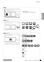
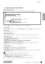
KEYPAD LOCK
The keypad can be locked by pressing the buttons in the following sequence:
ESC > UP > DOWN > ENTER
To unlock the keypad the buttons must be pressed in the reverse sequence:
ENTER > DOWN > UP > ESC
These sequences work only on MIMIC PANEL page.
When the keypad is locked the key symbol is shown (see figure below).


