


9
ITYS PRO
10-15-20 kVA - Ref.: IOMITYPRXX00-EN 03
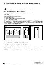
ENGLISH
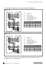
3.1-2
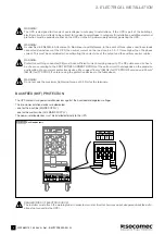
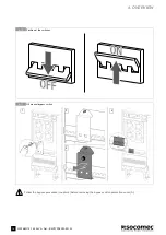
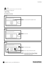
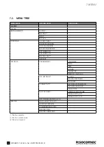
Warning label (supplied with the equipment)
3.1-3
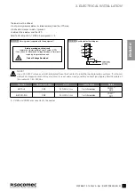
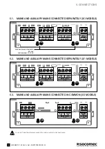
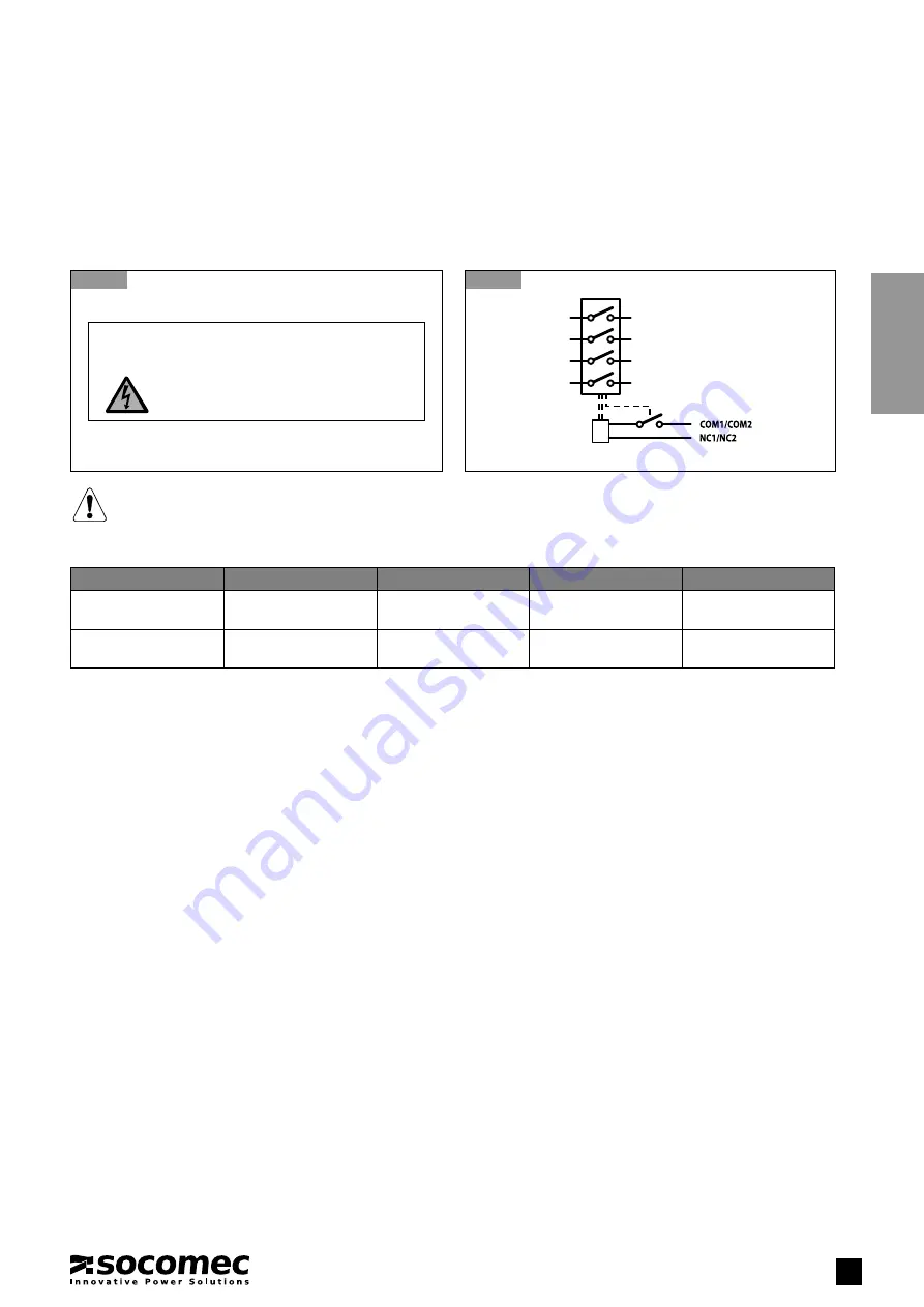
Backfeed electrical diagram
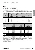
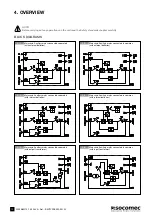
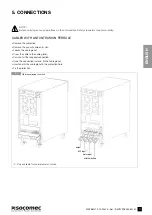
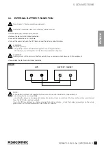
3. ELECTRICAL INSTALLATION
The label must be affixed:
• to all primary power isolators installed remotely from the UPS area;
• to all external access points, if present;
• between the isolators and the UPS.
Refer to CEI EN 62040-1 2009-05, paragraph 4.7.3.
Before working on this circuit
- Isolate the Uninterruptible Power System (UPS)
- Then check for Hazardous Voltage between all terminals
including the protective earth
Risk of Voltage Backfeed
B
L1
L2
L3
N
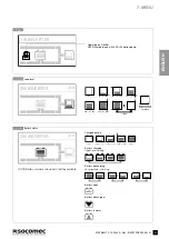
NOTE!
Use a 220-240 V release coil with integrated travel limit contact to pilot the input protection systems. If a trip coil
without an integrated end-of-travel contact is used, add an early auxiliary contact (see figure). Electrical data of
the contacts: 1.6 A 250 Vac.
Function
Connector name
V OUT
Internal fuse
Detail
BKF AUX
XB2
220-240 V rms
1.6 A time delay
COM 2
(1)
NC2
BKF MAINS
XB3
220-240 V rms
1.6 A time delay
COM1
(1)
NC1
(1). COM1 and COM2 are connected to the neutral.