

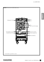

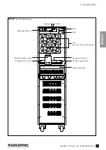
8
ITYS PRO
10-15-20 kVA - Ref.: IOMITYPRXX00-EN 03
3.1-1
Backfeed outputs
WARNING!
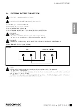
The UPS is designed for transient overvoltages in category II installations. If the UPS is part of the building’s
electrical circuit, or is likely to be subject to transient overvoltages in category III installations, additional external
protection must be provided, either on the UPS or in the AC power supply network powering the UPS.
WARNING!
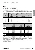
As specified in EN62040-3 Attachment 3: Non-linear Load Reference, in the event of three-phase non-linear loads
connected downstream of the UPS, the neutral current on the load can be 1.5 - 2 times higher than the phase
current. This must be considered when estimating the correct size of the output and the auxiliary neutral cables.
WARNING!
Protective earthing conductor (PE) must have sufficient current-carrying capacity. The PE cable core size has to
be chosen according to the PROTECTIVE CURRENT RATING of the earth circuit that depends on the provision
and location of over-current protective devices. We suggest 16 mm
2
(AWG4) for ITYS PRO 3/3 version and 25 mm
2
(AWG2) for ITYS PRO 3/1 version using the protective devices in the table above.
WARNING!
Do not excede the maximum tightening torque of 2.5 Nm for the terminals.
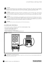
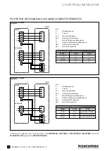
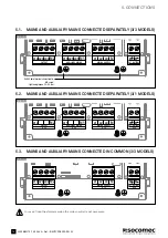
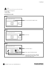
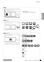
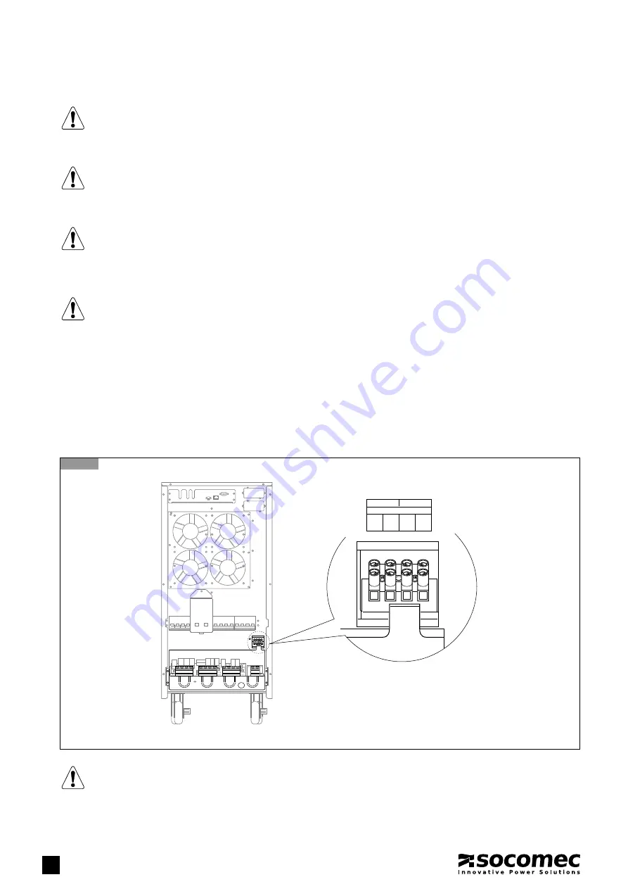
BACKFEED (BKF) PROTECTION
The UPS protects two power isolation devices against the backfeed of dangerous voltages.
The two power isolation devices are dedicated:
- one for the input line (MAINS SUPPLY);
- one for the auxiliary line (AUX MAINS SUPPLY).
The power isolation devices must be installed externally to the UPS.
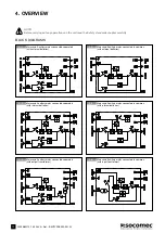
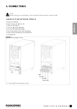
3. ELECTRICAL INSTALLATION
COM2
COM1
NC1
NC2
EXTERNAL BACKFEED
XB3
XB2
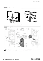
DANGER! RISK OF ELECTRIC SHOCK!
The installer must attach the warning label in order to warn electrical technicians about dangerous backfeed situ-
ations (not caused by the UPS).