Page 3 - 8
TL49J
MAINTENANCE PROCEDURE
POWER PACK
The power pack consists of a fully integrated pump,
tank, preset relief valve and a return filter. The biggest
cause of hydraulic problems is due to contaminated
oil and filter. The oil and filter needs changing at least
every 6 months even though the hydraulic system is
a closed system. The only access for external dirt is
through the filter breather. Contamination will occur
due to seal kit wear (black sludge in the bottom of the
tank, mechanical wear from the gear pump, valve block
and cartridges in addition to water contamination due
to tank condensation). Refer to the power pack section
for more details.
The hydraulic system is fully self contained. Oil tank
capacity is 15 litres. When operating above 0°C,
ISO22 grade hydraulic mineral oil (refer to health &
safety guidelines supplied with the oil prior to
handling) is recommended.
The main cause of hydraulic issues, sticking valves and leaking cylinders is due to contaminated oil.
There is no need to replace the oil in the hose. R
eplace the oil in the tank and filter every 6 months.
Oil is not discharged from the system and as a result, if oil is required, this would indicate an oil leak
which must be investigated prior to using the machine.
CORRECT OIL LEVEL
It is critical that the correct oil level is maintained. Too little oil will cause cavitation and failure of the
pump. Too much oil will lead to oil leak through the return filter breather or a massive oil leak when
using the emergency lower valves on the top and bottom boom. When using the emergency lower
valves, enough space is required in the tank to accommodate oil which normally would be pumped
into the annular side of the cylinder. If this should happen, clean up the oil spillage. Fully extend all
rams and then close up all the rams to check for the amount of free space in the tank using the dip
stick. The correct level expected is that at the bottom mark of the dipstick.
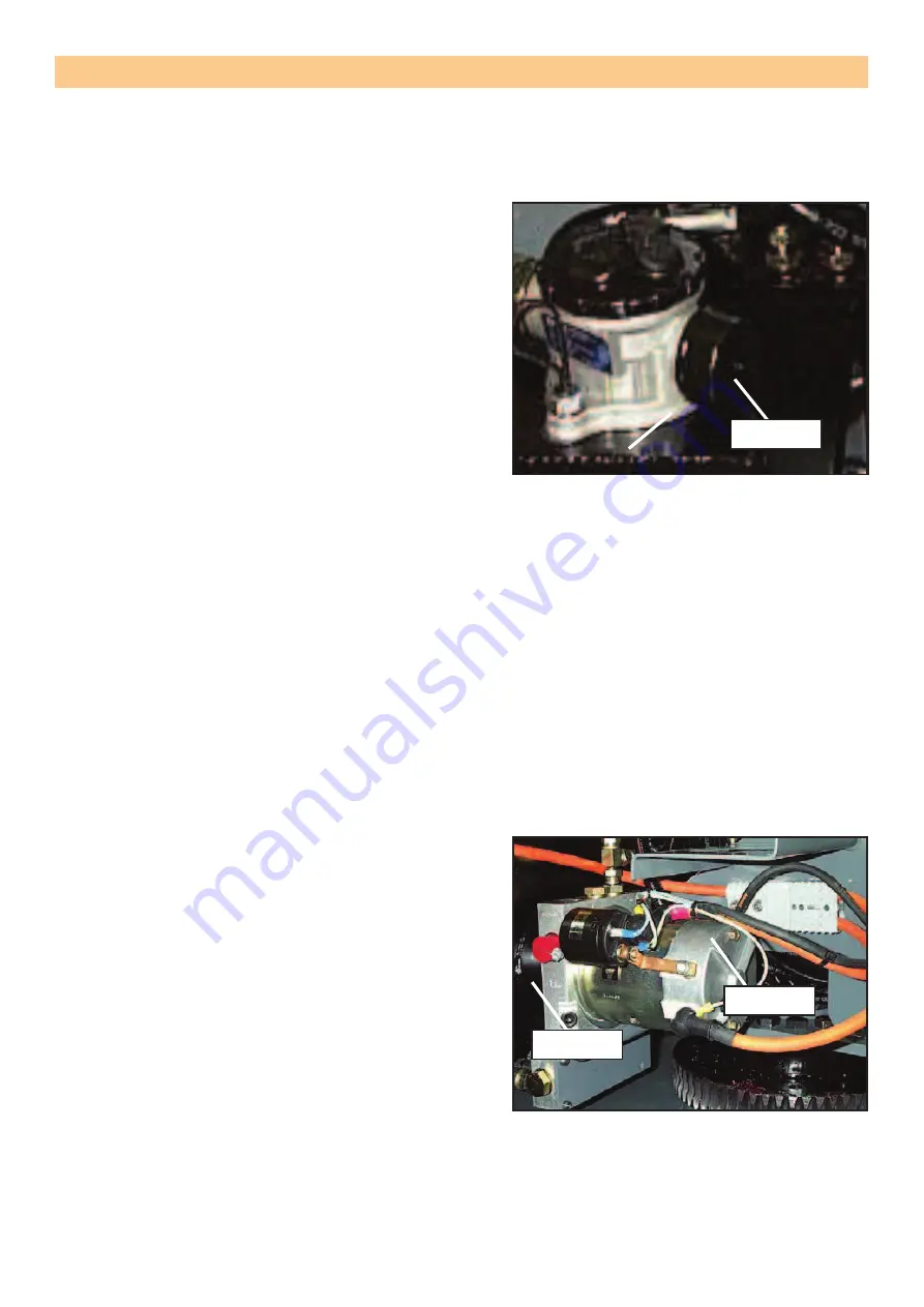
DC MOTOR & PUMP
The hydraulic pump is submerged in the tank. Oil
is drawn in through a suction strainer protecting the
pump. The DC motor is directly coupled to the pump
shaft. On the AC motor, a small adaptor coupling is
used between the motor and pump shaft. To replace
the pump;
1. Remove the tank by removing the 4 bolts secur-
ing it in place.
2. Remove the power pack from the machine.
3.
Remove the 4 fixing bolts securing the pump to
the aluminium block.
4. With the pump removed, inspect the gears for
wear.
5. If the gears are worn out or broken, replace the
complete pump. The replacement pump is a unit
consisting of the gears but without the strainer.
6.
Torque the 4-5/16 hex fixing bolts evenly to
17.63 Nm (13 ft/lbs) to ensure correct operation
of the pump. Do not overtighten.
7.
Before re-fitting, thoroughly clean the tank and the magnet found inside.
8. De-grease and replace the large “O” ring and apply a small amount of silicone around the
circumference of the de-greased tank neck.
9. Place the tank back on and secure with the 4 bolts removed earlier.
SERVICE AND REPAIR
Figure 3-1
: Filter breather location.
Figure 3-2
: DC motor coupled to the pump
shaft.
Filter Breather
DC Motor
Pump Shaft


