background image

MODULE OVERHANG

(NOT TO EXCEED 25%

OF MODULE LENGTH)

RAIL SPAN

RAIL END OVERHANG

(NOT TO EXCEED 34% OF

 ACCEPTABLE RAIL SPAN)

Building Height

0 - 30 ft

Array Pitch

16°

2012 IBC Wind Speed

120 mph

Snow Load

8 lbs/ft²

Topo. Cond.

None

Rail Span

104"

Rail Span on 24" spacing roof

96" (8 ft)

Do edge/corner reductions apply

Yes, shaded cell

Edge Zone Span

72" (6 ft)

Corner Zone Span

24" (2 ft)

3

Safety Guidance

- Always wear the proper OSHA approved 

safety equipment when working on a roof .

- Safety equipment should be checked 

annually for wear and quality. 

- Always wear proper eye protection. 

- When walking on the roof avoid walking 

on installed rails.  If this is unavoidable check 

L-feet for fatigue before final installation. 

- Appropriate fall protection gear should 

be used. Extreme caution should be 

used when near the edge of the roof.

Series 100 UL

Roof Mounted System

How to Configure Your System

First calculate the spans and penetration count. See span 

tables in structured engineering letters under the resources 

tab of the SnapNrack website. Determine site conditions: 

general building height, array pitch, the wind speed, and 

snow load or topographical condition. Find appropriate 

railspan from table.

Span Table Example

*CS-Consult 

  Structural Engineer

Notes

- The UL Listing covers bonding 

for a load rating up to 45 psf. 

- See Appendix A for the list of modules

that have been tested with the Series 100

UL system.

- These systems have been evaluated 

for module to system bonding, only to 

the requirements of UL Subject 2703.

- This system has also been 

evaluated for a Class A System Fire 

Classification for a steep-sloped roof 

with Type 1 and Type 2 modules.

- Installing Contractor is responsible for 

verification that attachments to roof 

framing are fully engaged into appropriate 

structural member and that structural 

member is adequate for support of roof 

mounting component and associated loads.

Summary of Contents for Series 100 UL

Page 1: ...1 PV Mounting System 2703 SERIES 100 UL ROOF MOUNT SYSTEM Code Compliant Installation Manual SnapNrack Solar Mounting Solutions...

Page 2: ...lar installation technicians With SnapNrack you will be able to solve virtually any PV module mounting challenge Table of Contents Step 1 Project Plans Configuration 3 Surveying and Layout 4 Step 2 Ro...

Page 3: ...ed System How to Configure Your System First calculate the spans and penetration count See span tables in structured engineering letters under the resources tab of the SnapNrack website Determine site...

Page 4: ...array Identify any construction anomalies that may complicate the process of locating rafters from the roof surface If you find structural problems such as termite damage or cracked rafters that may c...

Page 5: ...lamps on the rails Module mid clamps are installed between modules in a row and require 0 5 of space between the modules Adjustable end clamps require 1 5 of extra rail to extend past the end of the m...

Page 6: ...ut 5 16 18 Material 6000 Series Heat Treated Aluminum Finish Class 2 Anodized Finish Clear and Black Finish Available Weight 0 16 LBS Design Uplift Load 200 LBS Uplift Design Ultimate Load 1000 LBS Up...

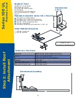
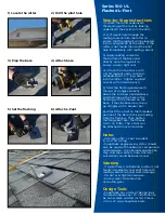
Page 7: ...ugh the roofing material into the rafter to ensure that the lag bolt will be located into a solid portion of the rafter If the rafter is not found then seal the pilot hole immediately with roofing sea...

Page 8: ...16 18 X 2in SS HCS Bolt 1 SnapNrack Bonding Channel Nut 5 16 18 1 5 16 Lag Screw 1 5 16 Washer 1 Roof Cone Flashing Material 6000 Series Heat Treated Aluminum Finish Mill Weight 5 5 Shaft 0 4 LBS 7 S...

Page 9: ...e eave in the attic or by tapping the roof surface with a hammer 2 Drill a pilot hole through the roofing material into the rafter to ensure that the lag bolt will be located into a solid portion of t...

Page 10: ...Roof Cone Flashing Materials Included In Series 100 Four Hole Standoff Kit Other Materials Required 1 SnapNrack Four Hole Standoff Base 1 SnapNrack Standoff Shaft 1 SnapNrack Rubber Rain Collar 1 Sna...

Page 11: ...ication that attachments to roof framing are fully engaged into appropriate structural member and that structural member is adequate for support of roof mounting component and associated loads Step by...

Page 12: ...ocket Wrench or impact driver Flat Pry Bar Materials Included In Universal Tile Roof Hook 1 SnapNrack Universal Tile Roof Hook Base 1 SnapNrack Universal Tile Roof Hook Arm 2 5 16 Flange Bolt 2 SnapNr...

Page 13: ...ound then seal the pilot hole immediately with sealant 3 Apply roofing sealant to the bottom of the base and directly onto each lag screw Attach the base with two 5 16 lag screws with washers at a min...

Page 14: ...1 5 16 Flange Bolt 1 SnapNrack Bonding Channel Nut 5 16 18 Other Materials Required 2 5 16 Lag Screw 2 5 16 Washer Roof Felt of Flexible Flashing when required for deck level flashing Material 304 Sta...

Page 15: ...ger be valid Step by Step Instructions 1 Use pry bar to remove roof tile where the Tile Hook will be installed Locate the rafter underneath the decking of the roof by locating under the eave in the at...

Page 16: ...st or foreign matter that may prevent adhesion Clean the surface around the Tile Hook with a brush of medium stiff bristles If necessary prime the surface with compatible spray or paint primer 2 Peel...

Page 17: ...16 SS Split Lock Washer 1 5 16 18 X 1in SS HCS Bolt 1 SnapNrack Bonding Channel Nut 5 16 18 Material 6000 Series Heat Treated Aluminum Color Class 2 Anodized Finish Clear Finish Available Weight 0 7 L...

Page 18: ...y void the warranty and structural calculations could become invalid Step by Step Instructions 1 Locate the rafter underneath the decking of the roof 2 Drill a pilot hole through the roofing material...

Page 19: ...tud Finder Roof Marking Crayon Drill with 3 16 Pilot Drill Bit Torque Driver with Bit Adapter 1 2 Socket Wrench or impact driver Material 6000 Series Aluminum Color Clear Anodized Aluminum Weight 0 4...

Page 20: ...t to avoid water damage Do not over tighten hardware Always wear fall protection and safety gear Notes Metal roofs with excessive debris corrosion or non factory coating should be evaluated for adequa...

Page 21: ...rench or impact driver 1 SnapNrack Corrugated Straddle Block 1 5 6 Lag Screw 1 5 16 Washer Material 6000 Series Heat Treated Aluminum Color Mill Finish Weight 0 3 LBS Design Uplift Load 200 LBS Uplift...

Page 22: ...application may void the warranty and structural calculations could become invalid Step by Step Instructions 1 Locate the rafter underneath the decking of the roof by locating the screws The rafter l...

Page 23: ...Treated Aluminum Finish Mill Weight 5 5 Shaft 0 4 LBS 7 Shaft 0 5 LBS 8 5 Shaft 0 6 LBS Design Uplift Load 200 LBS Uplift Design Ultimate Load 1000 LBS Uplift Hammer or Stud Finder Roof Marking Crayo...

Page 24: ...Locate the rafter underneath the decking of the roof by tapping the roof surface with a hammer 2 Drill a pilot hole through the roofing material into the rafter to ensure that the lag bolt will be loc...

Page 25: ...doff Clamp 4 5 16 SS Split Lock Washer 3 5 16 X1 1 4 SS HCS Flange Bolt 1 5 16 18 SS Flat Hex Nut 2 5 16 18x2 SS HCS Bolt 2 SnapNrack L Foot 4 SnapNrack Bonding Channel Nut Material 6000 Series Heat T...

Page 26: ...hammer 2 Drill a pilot hole through the roofing material into the rafter to ensure that the lag bolt will be located into a solid portion of the rafter If the rafter is not found then seal the pilot h...

Page 27: ...s Included In Series 100 Wide Seam Clamp Kit Dimensioned Wide Seam Clamp Technical Seam Clamp Data Material 6000 Series Heat Treated Aluminum Finish Mill Design Uplift Load 200 LBS Uplift Design Ultim...

Page 28: ...Wide Base VP Buildings SSR Standard Base Whirlwind Super Seam II Standard Base 28 3 Tighten hardware 1 Assemble seam clamp 2 Attach seam clamp Series 100 UL Seam Clamp Design Tools SnapNrack has a sui...

Page 29: ...1 SnapNrack Standoff Spacers 5 16 18 X 1 Fully Threaded Set Screw Pre installed SnapNrack Roof Attachments L Foot Or Standoff Material 6000 Series Heat Treated Aluminum Finish Class 2 Anodized Finish...

Page 30: ...Sola modules 3 93 Trina Solar modules 4 53 Step by Step instructions 1 Set all of the rails into the attachments by snapping the channel nuts into the side channel of the standard rail Connect multipl...

Page 31: ...t is as high in channel as it can go While lifting up on insert tighten bolts by hand to secure insert in channel Note loosening bolts prior to lifting up insert to engage it into channel will provide...

Page 32: ...Bolt 1 5 16 SS Split Lock Washer 1 SnapNrack Bonding Mid Clamp 1 5 16 18 SnapNrack Bonding Channel Nut 1 5 16 18 2x3 4 SS HCS Bolt 1 5 16 SS Split Lock Washer 1 SnapNrack Self Adjusting Top 1 SnapNrac...

Page 33: ...e top lip of the mid clamp over the top edge of the module 3 Place the next module flush to the other side of the mid clamp 4 Tighten hardware torque silver hardware to 10 16 ft lbs and black hardware...

Page 34: ...als Included With Series 100 Edge Screen Technical Edge Screen Data Dimensioned Edge Screen Clip Dimensioned Assembly Screen Material Galvanized Steel 1 2 Mesh Color Black PVC Coating Weight 0 18 LBS...

Page 35: ...nts and hardware Any alternate application may void the warranty and structural calculations could become invalid Step by Step Instructions 1 Hold the SnapNrack edge screen clip upside down up to the...

Page 36: ...Series 100 Rail Cover Technical Rail Cover Data Dimensioned Rail Cover Material 6000 Series Heat Treated Aluminum Color Class 2 Anodized Finish Clear Finish Available Weight 0 155 LBS FT 1 SnapNrack...

Page 37: ...become invalid Step by Step Instructions SnapNrack Rail Cover 1 Measure the length of the SnapNrack rail cover that is needed SnapNrack standard lengths of rail covers are 48 2 Cut the rail cover to...

Page 38: ...Micro Inverter Attachment Kit Dimensioned Assembly Micro Inverters May Have Separate Grounding Which Will Not require a WEEB 1 5 16 X 1 5 X 0 187 SS Fender Washer 1 SnapNrack Bonding Channel Nut 5 16...

Page 39: ...ar Notes SnapNrack engineered systems should only be used with SnapNrack components and hardware Any alternate application may void the warranty and structural calculations could become invalid Step b...

Page 40: ...ground the system except Universal End Clamps 40 System Ground Methods Include SnapNrack Mid Clamp SnapNrack Universal End Clamp SnapNrack X End Clamp SnapNrack Ground Lug Ilsco Lay in Lug SnapNrack...

Page 41: ...SnapNrack engineered systems should only be used with SnapNrack components and hardware Any alternate application may void the warranty UL 2703 Listing and structural calculations could become invalid...

Page 42: ...2 Dimensioned Rail Cutting Tool Dimensioned End Cap Required Tools Materials Included In Series 100 Rail Cutting Tool and End Cap 1 SnapNrack Rail Cutting Tool 1 SnapNrack Rubber End Cap Reciprocatin...

Page 43: ...e application may void the warranty and structural calculations could become invalid Rail Cutting Tool and End Clamp 1 Slide the Cutting tool over the end of the rail and place it so that the upper li...

Page 44: ...t 1 48 Scrap Piece Of Rail 2 5 16 Split Lock Washer 2 4 Rail Covers With 3 8 Holes Drilled In Center 2 5 16 X 3 4 Flange Bolts Drill Measuring Tape Reciprocating Saw 1 2 Socket Wrench 2 SnapNrack Chan...

Page 45: ...round scrap piece of rail to the dimensions of the panels being installed Drill 3 8 holes in each rail cover Cut two 5 16 channel nuts to length Drill holes into channel nuts Obtain all of the parts r...

Page 46: ...275MG all may be followed by the suffix BK or blank Renesola Jiangsu Ltd JCxxxM 24 BB Series JC200M 24 Bb JC205M 24 Bb JC210M 24 Bb JC215M 24 Bb JC220M 24 Bb JC225M 24 Bb JC230M 24 Bb JC235M 24 Bb JC2...

Page 47: ...05 08 TSM 245PD05 08 TSM 250PD05 08 TSM 255PD05 08 TSM 260PD05 08 NRTL Listed PV Modules Hanwha SolarOne Models HSL60P6 PB 2 230Q HSL60P6 PB 2 235Q HSL60P6 PB 2 240Q HSL60P6 PB 2 245Q HSL60P6 PB 2 250...

Page 48: ...48 Notes...

Reviews: