background image

50


Quick Start Guide


51

3D Printing 

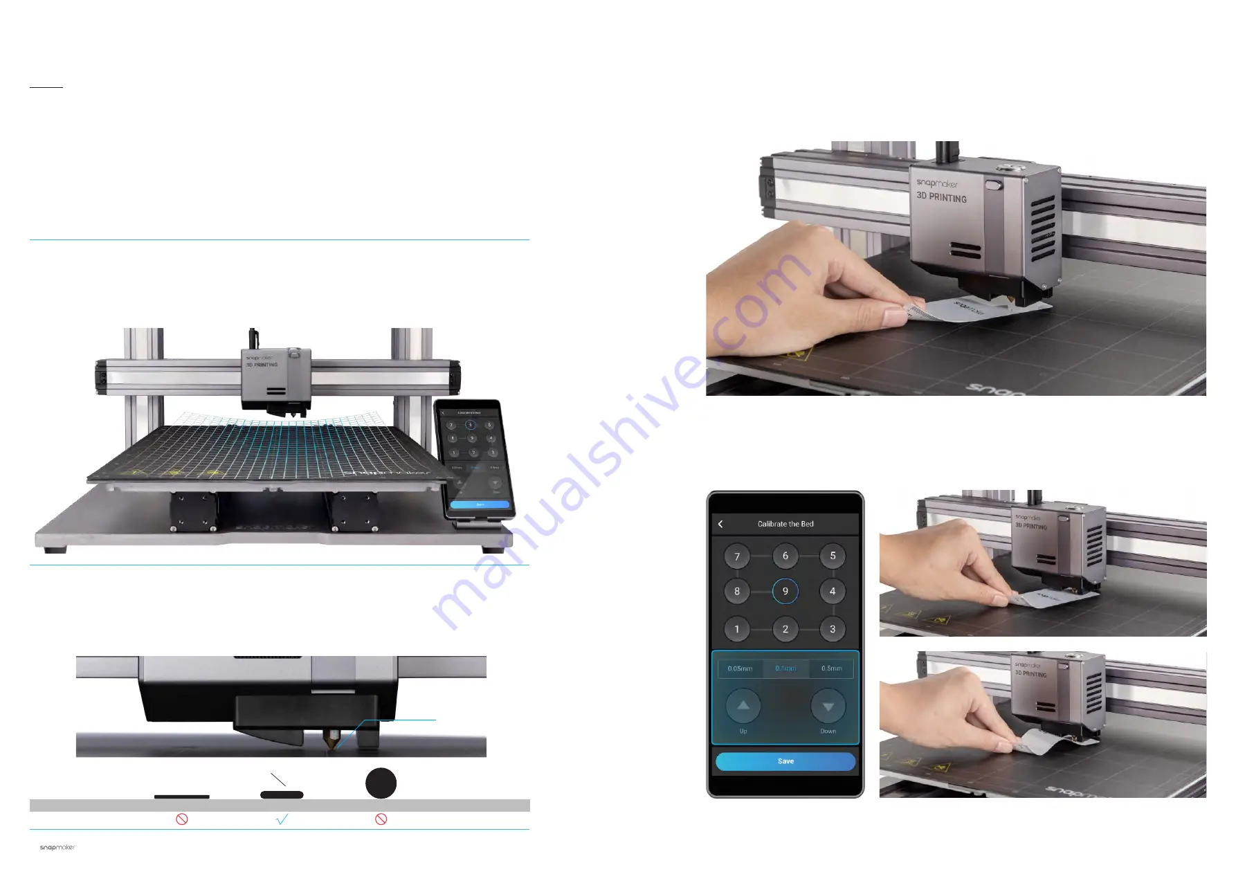
3.2.1 Calibrate the Bed

How It Works: Auto Leveling

The 3D Printing Module conducts a leveling procedure, with the sensor measuring the distance between the 
nozzle and the Heated Bed at specific points. The movements of the extruder are adjusted to ensure that the 
nozzle and the Heated Bed are at an optimum distance throughout the printing process.  

How It Works: Adjusting the Z Offset

Z Offset is the distance between the tip of the nozzle and the print surface. Adjusting the Z Offset is the 
process of tweaking the height of the nozzle by tiny increments. A proper Z Offset value helps ensure the 
first layer of your print sticks to the Print Sheet.

Guides & Pictures 

/ Snapmaker

0.1 mm

Filament

Too Low

Too High

Print Sheet

3. Keep adjusting the height of the nozzle using 

Up

 and 

Down

 buttons, until you feel slight resistance when you 

pull out the Calibration Card, and it should be wrinkled when you push it forward. Tap 

Save

 to save the calibration 

settings.

Slight Resistance

Wrinkled Calibration Card

How to Level

1. Run the Auto Leveling procedure on the touchscreen.

2. Place the Calibration Card or a piece of A4 paper between the nozzle and the Heated Bed, and manually 
calibrate the Z Offset for the last point.

Summary of Contents for A350T

Page 1: ...QUICK START GUIDE MAKE SOMETHING WONDERFUL A350T...

Page 2: ...he impossible possible Not only did we fulfill all the rewards but we also sold over 10 000 units all over the world in 2018 And in 2019 we launched the Snapmaker 2 0 We went beyond our limits once ag...

Page 3: ...itious as exploring unknown territories of our mankind Dream big and make it happen Happy Making Snapmaker is not only a 3D printer but also a powerful machine that you can customize with addons You c...

Page 4: ...Quick Start Guide 1 01 12 40 60 76 Before You Start Machine Assembly 3D Printing Laser Engraving and Cutting CNC Carving CONTENTS BEFORE YOU START...

Page 5: ...or loss injuries damage or expense arising out of or in any way connected with the assembly handling storage use maintaining or disposal of this product 1 2 Intended Use Snapmaker modular 3D printers...

Page 6: ...d to try to correct the interference by one or more of the following measures Reorient or relocate the receiving antenna Increase the separation between the equipment and receiver Connect the equipmen...

Page 7: ...T Android System Snapmaker Luban and third party software stl obj svg jpeg png more formats to be added MacOS Windows Linux 320 W A250T 230 x 250 x 235 mm A350T 320 x 350 x 330 mm A250T Up to 100 C A3...

Page 8: ...Power Cable x 1 Toolhead Cable x 1 Print Sheet x 1 Platform x 1 Material Bag x 1 CNC Carving Platform x 1 Laser Engraving Cutting Platform x 1 Heated Bed x 1 Laser Safety Goggles x 1 Filament Holder S...

Page 9: ...eo tutorials Read this guide to finish assembly and if you are feeling adventurous tricks that are not included in this guide can be found in the video tutorials Visit our website at https support sna...

Page 10: ...12 Quick Start Guide 13 Machine Assembly MACHINE ASSEMBLY...

Page 11: ...led in their intended position Now identify two Linear Modules with the laser pattern Lead 20 mm they will be the Y Axes There are three Linear Modules engraved with the laser pattern Lead 20 mm The u...

Page 12: ...the screws until Step 6 Platform x 1 Make sure to assemble the Platform in correct orientation 03 24 Make sure the sliders are aligning with each other If not you can move them to the same position as...

Page 13: ...4 x 8 Screw x 16 Make sure the Y axis Linear Modules are accurately mounted onto the grooves of the Base Plate If the screws on the sliders are not aligning with the screw holes on the Base Plate move...

Page 14: ...tart Guide 21 Machine Assembly M4 x 8 Screw x 8 Z axis Holder x 2 07 24 Attach the Z axis Holders to the Base Plate M4 x 8 Screw x 2 Touchscreen Holder x 1 08 24 Attach the Touchscreen Holder to the B...

Page 15: ...0 24 Thread the connecting cables through the holes of the holders and then attach the Z Axes to the Z axis Holders Do not tighten the screws until Step 14 09 24 Identify the two Linear Modules with t...

Page 16: ...ly M4 x 8 Screw x 8 11 24 Install the screws to the bottom of the Z Axes Do not tighten the screws until Step 15 12 24 From the middle move the Platform to the position as illustrated Then move the Z...

Page 17: ...near Module x 1 13 24 The last Linear Module with the laser pattern Lead 20 mm will be the X Axis Attach the X Axis to the Sliders on the Z Axes M4 x 8 Screw x 8 14 24 Tighten the screws that are used...

Page 18: ...Tighten the screws to the bottom of the Z Axes Make sure both ends of the Linear Module are in horizontal alignment with each other throughout the process 16 24 Put your hands at each end of the Line...

Page 19: ...x 1 Y Conversion Cable x 1 17 24 Locate the Y Conversion Cable and the attached cable on both of the two Y Axes as illustrated Connect them to the Converter Y Conversion Cable x 1 M4 x 30 Screw x 4 1...

Page 20: ...e x 1 19 24 Locate the Z Conversion Cable and the attached cable on both of the two Z Axes as illustrated Connect them to the Converter Z Conversion Cable x 1 M4 x 30 Screw x 4 20 24 Attach the Z axis...

Page 21: ...Bed Power Screen USB Toolhead Add on 1 Add on 2 X Axis Y Axis Z Axis 22 24 Open the dust plugs and then connect the X Y and Z Axes with the Controller Keep the protective dust plugs on the unplugged...

Page 22: ...reen and then connect the Touchscreen with the Controller Power Module x 1 AC Power Cable x 1 DC Power Cable x 1 Do not connect or disconnect any cables when the machine is powered on Make sure the po...

Page 23: ...y Absolutely amazing You have successfully assembled the machine body Now just select one function to complete the assembly and bring your first job into the world 3D Printing Laser Engraving and Cutt...

Page 24: ...3 1 Assembly 3 1 1 Assemble the 3D Printer 3 1 2 Initial Setup 3 2 Get Started 3 2 1 Calibrate the Bed 3 2 2 Load Filament 3 3 Start Printing 3 3 1 Prepare the G code File 3 3 2 Start Your First Print...

Page 25: ...on the X Axis 3D Printing Module x 1 M4 x 8 Screw x 4 3 1 1 Assemble the 3D Printer Guides Pictures Snapmaker Make sure the power switch is in the Off position 02 07 Connect the 3D Printing Module wit...

Page 26: ...e Filament Holder to the Z Axis M4 x 10 Hex Socket Head Screw x 2 1 1 Filament Holder Sheet x 1 Filament Holder Tube x 1 M4 x 10 Hex Socket Head Screw x 1 Heated Bed x 1 M4 x 10 Hex Flat Head Screw x...

Page 27: ...the Heated Bed is contamination free before you place the Print Sheet Make sure the Print Sheet aligns perfectly with the Heated Bed Print Sheet x 1 Add on 3 Heated Bed Power Screen USB Toolhead Add...

Page 28: ...he touchscreen Read the Terms Name the Machine Connect to a Wi Fi Network Guides Pictures Snapmaker It is recommended to wait for 5 seconds after you restart your machine Skip this step if you have co...

Page 29: ...the process of tweaking the height of the nozzle by tiny increments A proper Z Offset value helps ensure the first layer of your print sticks to the Print Sheet Guides Pictures Snapmaker 0 1 mm Filam...

Page 30: ...ilament using the diagonal pliers and then insert the filament into the 3D Printing Module 2 Tap Start on the Load Filament screen After the temperature reaches the target temperature tap Load and the...

Page 31: ...s refer to our Snapmaker Luban User Manual Files sent by Wi Fi can be found on the Touchscreen Files Local 1 Install the Software and Complete the Initial Setup Download our software the Snapmaker Lub...

Page 32: ...wipe left on the printing progress screen 3 3 2 Start Your First Print Guides Pictures Snapmaker If poor adhesion occurs swipe left on the printing progress screen and try adjusting the Z Offset Or yo...

Page 33: ...ment runs out tap Ready to Load and load new filament to resume printing In case of power loss tap Recover to resume printing after the power has been restored Firmware Update It is recommended to upd...

Page 34: ...4 1 Assembly 4 1 1 Assemble the Laser Engraver and Cutter 4 1 2 Initial Setup 4 2 Get Started 4 2 1 Measure the Focal Length 4 2 2 Calibrate the Camera 4 2 3 Fasten the Material 4 3 Prepare the G code...

Page 35: ...er and Cutter Guides Pictures Snapmaker 01 04 Attach the Laser Module to the slider on the X Axis Make sure the power switch is in the Off position Make sure the connector is in the right direction 02...

Page 36: ...ng Platform to the Platform Laser Engraving Cutting Platform x 1 M4 x 10 Hex Socket Head Screw x 14 1 1 04 04 Attach the Cable Holder to the Z Axis and then lock the Toolhead Cable into place M4 x 8 S...

Page 37: ...et started will appear only once If you need to launch it again swipe left on the homepage of the Touchscreen select Settings tap Guides 4 2 1 Measure the Focal Length Guides Pictures Snapmaker How It...

Page 38: ...igin in the software How to Measure the Focal Length 1 Place the provided material on the Laser Engraving Cutting Platform Secure it with the silicone plugs 2 Set the thickness of the material 1 5 mm...

Page 39: ...eed to remeasure the focal length refer to our online User Manual for detailed instructions 1 Remove the engraved material Place a piece of blank white paper no less than 150 mm x 150 mm on the center...

Page 40: ...ides Pictures Snapmaker 4 3 Prepare the G code File and Start Cutting Guides Pictures Snapmaker 1 Download our software the Snapmaker Luban at https www snapmaker com download and install Then connect...

Page 41: ...mplete the assembly Share Share your finished work in our Facebook group and our forum You can also upload your own files by clicking and configure the file settings You can also start engraving cutti...

Page 42: ...5 1 1 Assemble the CNC Carver 5 1 2 Initial Setup 5 2 Get Started 5 2 1 Fasten the Material 5 2 2 Attach the Bit 5 3 Start Carving 5 3 1 Prepare the G code File 5 3 2 Set the Work Origin and Start Ca...

Page 43: ...der on the X Axis CNC Module x 1 M4 x 8 Screw x 4 5 1 1 Assemble the CNC Carver Guides Pictures Snapmaker Make sure the power switch is in the Off position 02 04 Connect the CNC Module with the Contro...

Page 44: ...orm to the Platform CNC Carving Platform x 1 M4 x 10 Hex Socket Head Screw x 14 1 1 04 04 Attach the Cable Holder to the Z Axis and then lock the Toolhead Cable into place M4 x 8 Screw x 2 Cable Holde...

Page 45: ...f the Touchscreen select Settings tap Wi Fi or About Machine as needed The initial guide which helps you get started will appear only once If you need to launch it again swipe left on the homepage of...

Page 46: ...fasten the material How It Works CNC Bit Usage Flat End Mill is typically used for slotting or cutting materials into flat surface Ball End Mill is typically used for carving materials into curved su...

Page 47: ...tial Setup Download our software the Snapmaker Luban at https www snapmaker com download and install Then connect Snapmaker Luban to your machine through the same Wi Fi network Enter Workspace Connect...

Page 48: ...eceiving the G code file tap Disconnect on the Touchscreen Then find and select the received G code file and tap Next to enter the Set Work Origin screen 2 Tap X X Y Y Z or Z to move the CNC Bit to wh...

Page 49: ...kled Calibration Card 3 Place the Calibration Card or a piece of A4 paper between the CNC Bit and the material Keep adjusting the height of the CNC Bit using Z or Z buttons until you feel slight resis...

Page 50: ...pport snapmaker com For any sales inquiries sales snapmaker com For product purchases https shop snapmaker com Share anything you want with other Snapmaker users in our forum https forum snapmaker com...

Page 51: ...94 CNC Carving...

Reviews: