background image

© 2015 SensoMotoric Instruments (SMI)

RED250mobile System User Guide

Page 50

4.

Getting Started

Follow these steps to get started using the RED250mobile System.
Detailed instructions are provided in later sections of this User Guide. 
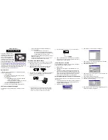
1. Preparation:

a. Download and run the 

iViewRED

 Installation Package, which is

available at www.smivision.com/software/.

b. After 

iViewRED

 has been installed, run the application.

c. Connect the 

 RED250mob ile Eye Tracker

 to an available USB port on

the PC or Laptop. 

The 

RED250mob ile Eye Tracker

 requires a USB 2.0

port. 

d. The 

Geometry

 tab will be displayed in 

iViewRED

.

e. On the 

Geometry

 tab, select the type of display used from the 

Display

Type

 dropdown menu. Select 

Laptop Display

 or 

Desktop Monitor

.

f. On the 

Geometry

 tab, click 

Setup Guide

. This will display a vertical

line on the screen in the exact horizontal center of the selected
screen. It is used to correctly mount the 

RED250mob ile Eye Tracker

on a Laptop Display or Desktop Monitor.

2. Mount the 

RED250mobile Eye Tracker

:

a. Select a Mounting Bracket from the available Mounting Brackets. The

20° Mounting Bracket is provided as standard. A 15° and 25°
Mounting Bracket are available from SMI.

b. Insert the Mounting Strip into the Mounting Bracket.

Summary of Contents for RED250mobile

Page 1: ...RED250mobile System User Guide Version 4 2 1 June 2015 ...

Page 2: ... 2015 SensoMotoric Instruments SMI RED250mobile System User Guide Page ii ...

Page 3: ...rmity 11 1 6 Product Maintenance 12 1 7 Document Conventions 13 1 8 Glossary Part 2 18 System Overview 19 2 1 System Requirements 22 2 2 RED250mobile Eye Tracker 24 2 3 iViewRED Software 26 2 4 Accessories 27 2 5 Optimal Conditions Part 3 30 iViewRED Software Overview 30 3 1 Geometry Tab 35 3 2 Calibration Tab 40 3 3 Settings Tab 42 3 4 Info Tab 44 3 5 Profile Selector 46 3 6 Eye Tracking Monitor ...

Page 4: ...cker 64 7 1 Mounting Guides 65 7 2 Mounting Instructions Part 8 72 Managing Profiles 72 8 1 Creating and Modify Profiles 74 8 2 Selecting Profiles 75 8 3 Deleting Profiles Part 9 78 Setting Geometry Measurements 78 9 1 Using Multiple Displays 79 9 2 Selecting Type of Display 81 9 3 Required Measurement Values 82 9 4 Automatically Detecting Measurement Settings 84 9 5 Manually Entering Measurement ...

Page 5: ...alibration 11 2 2 109 2 Point Calibration 11 2 3 110 5 Point Calibration 11 2 4 111 9 Point Calibration 11 2 5 112 13 Point Calibration 11 2 6 113 11 3 Setting Animation Speed 113 11 4 Accepting Calibration Points 114 Using Smart Calibration 11 4 1 115 11 5 Setting Calibration Point Styles 116 11 6 Running a Validation 119 11 7 Understanding the Results 121 11 8 Recalibrating on a Point Part 12 12...

Page 6: ...nterfacing with other Applications 146 Interfacing with SMI Experiment Center 15 7 1 146 Working in a Dual PC configuration 15 7 1 1 147 Interfacing with Third Party Applications 15 7 2 147 Application Running on iViewRED PC 15 7 2 1 148 Working in a Dual PC configuration 15 7 2 2 150 15 8 Evaluating Eye Tracking Data 150 Evaluation with SMI Experiment Suite 15 8 1 150 Working with the iView Data ...

Page 7: ...1 Chapter Welcome ...

Page 8: ...obile System This system includes the RED250mobile Eye Tracker and the iViewRED software which is used to configure and run the RED250mobile Eye Tracker Document Information Document Version 1 1 Release Date June 2015 Software Version 4 2 1 Copyright 2015 SensoMotoric Instruments SMI All other product names are copyright of their respective owners For rights and responsibilities of the use of this...

Page 9: ...4513 Teltow Germany Phone 49 0 3328 3955 510 Fax 49 0 3328 3955 599 e mail sales smi de Web www smivision com SensoMotoric Instruments Inc 236 Lewis Wharf Boston MA 02110 United States of America 5 3rd Street San Francisco CA 94103 United States of America Phone 1 617 557 0010 Fax 1 617 507 8319 e mail sales smivision com Web www smivision com ...

Page 10: ...panying the SOFTWARE The user is not entitled to allow a third party to use the software simultaneously without written approval of SensoMotoric Instruments GmbH Independent branch offices or subsidiary companies are also understood to be a third party in this sense SensoMotoric Instruments GmbH and or its supplying firm remain the owners of the delivered software even if it is altered The followi...

Page 11: ...e these operating instructions In addition any unauthorized modifications or repairs of the device will render the warranty null and void Make sure the presented visual stimuli or the environment in which you conduct your study does not harm or injure your participants SensoMotoric Instruments GmbH SMI is in no way responsible for the experiments you develop execute and analyze Furthermore do not ...

Page 12: ...e Eye Tracker away from heat sources No part of the product may be modified or rebuilt Any usage other than described in this manual is not permitted The RED250mobile Eye Tracker may warm up to 55 C during prolonged operation Magnet Precautions Neodymium magnets Rare Earth magnets are used in this device to connect it to the Mounting Bracket This allows the RED250mobile Eye Tracker to be easily di...

Page 13: ...ckly or if the device is dropped Metal items such a keys knives or tools may cause the magnet to shatter if placed near enough to the magnets to cause them to connect with the magnets Do not leave the RED250mobile Eye Tracker near an open flame or a heat source Aside from destroying the device the neodymium magnets may ignite burn and create toxic fumes Do not handle the RED250mobile Eye Tracker w...

Page 14: ...or place magnets in any body orifice such the ear nose or mouth Ingestion of magnets is very hazardous If magnets are ingested or aspirated into the lungs immediate medical attention is required Swallowed magnets can stick together across intestines causing serious infections and death Seek immediate medical attention if magnets are swallowed or inhaled Children under 3 should not handle magnets i...

Page 15: ... 2015 SensoMotoric Instruments SMI Welcome Page 9 by air These regulations also apply to magnets built in to products such as the Eye Tracker and Mounting Bracket ...

Page 16: ...Page 10 1 5 Declaration of Conformity All SMI eye tracking equipment has been tested and found to comply with the limits for Class B digital devices pursuant to Part 15 of the FCC Rules and EMC directive 2004 108 EC and conforms to the low voltage directive 2006 95 EC ...

Page 17: ... use Store it in the case Keep liquids and other contaminants away from the device Do not allow liquids of any kind to near or on the device to prevent permanent damage If the RED250mobile Eye Tracker becomes damaged we highly recommend that you Immediately unplug it from the USB port Do not use the device until it has been repaired or replaced Do not attempt to repair the RED250mobile Eye Tracker...

Page 18: ...ct names Bold Used for user interface buttons selections check boxes application windows and screen names Underlined In the PDF and Online Help version of this manual indicates references to a related topic in this manual or to internet addresses Note icon to indicate additional information Warning icon to indicate reader should pay careful attention to the information Reference See Also icon indi...

Page 19: ...ayed on a screen for a short duration Used during calibration Display Monitor Generally referring to the same device but in this document a Display refers to a Laptop screen while Monitor refers to a Desktop PC screen Experiment Center Developed by SMI this software is an easy to operate experiment creation planning and execution environment It is specially designed for eye tracking studies Experi...

Page 20: ...which the participant can move during the experiment and where tracking is possible is determined by tracking range and operating distance Monocular Left Tracking Mode Tracks only on the left eye channel Monocular Right Tracking Mode Tracks only on the right eye channel Operator Person who is responsible for running the experiment Also see Participant Operating Distance Distance between the partic...

Page 21: ...ked Tracking continues when one eye is closed or cannot be tracked Smart Calibration With Smart Calibration enabled the calibration process waits for required fixations for two seconds If fixation on one calibration point is found unreliable e g when the user was not really fixating that point or closing the eyes the data from this point will not be used to establish the calibration model The mode...

Page 22: ...mental stimuli to the participant during the experiment Tracking Mode Setting which determines how the eye tracker will track the participant s eyes Tracking Range Characterizes the surface of the plane in which eyes are detected by the eye tracker Validation Uses a new set of points to verify the accuracy of the calibration results ...

Page 23: ...2 Chapter System Overview ...

Page 24: ...ile and ready to use inside and outside of the lab The RED250mobile System consists of the ultra light USB powered fully portable RED250mobile Eye Tracker and the iViewRED software to configure the RED250mobile Eye Tracker for use with a participant as well as a dedicated SMI certified Laptop configured for use with the RED250mobile Eye Tracker SMI Experiment Suite is available as a recommended co...

Page 25: ...articular PC may interfere with the functioning of iViewRED software In short if you plan on using iViewRED on a PC other than an SMI provided PC it is possible that the recording output may be a lower quality The following instructions in this section are guidelines only on how to set up your PC Requirements Operating system Windows 7 32 or 64 bit Windows 8 32 or 64 bit Windows 8 1 32 or 64 bit O...

Page 26: ...Standby Mode Screen Saver Disable the screen saver Power Options Disable any function that will power down the PC after a period of inactivity Display Set to Never turn off Sleep Set to Never put the computer to sleep Power Plan Set to High Performance Closing the Lid Set to Do nothing Windows Updates During recording sessions only Set to Never Check for Updates Antivirus Software Add iViewRED to ...

Page 27: ...Applications Do not use additional applications that consume CPU or USB resources on the PC since they might have an impact on the eye tracker performance Firewall and Networking Adapt the firewall and network settings so that iViewRED can run properly Write Access Ensure the operator has write access to the repository directory Do not try to write to a folder for which you do not have write acces...

Page 28: ...onments familiar to participants It is connected to a USB 2 0 port on the Laptop or PC running iViewRED which also provides a power supply to the device It is mounted on the bottom frame of a Laptop Display or Desktop Monitor and can be easily removed for storage in the provided protective case Important Note About USB Ports The RED250mobile Eye Tracker is optimized for operation on a USB 2 0 port...

Page 29: ... resolution RMS 0 03 human Calibration 0 1 2 5 9 13 Points Smart Calibration technology Operating distance 50 cm to 80 cm Tracking range 32 cm x 21 cm at 60 cm distance Interfacing 8 TTL Operator feedback Eye Images Eye Tracking Monitor Interface setup Use with Desktop Monitor 10 to 24 or Laptop Display 10 to 24 Operating system Microsoft Windows 7 Windows 8 Windows 8 1 PC Interface power USB 2 0 ...

Page 30: ...pular stimulus software for example MATLAB PST E Prime Python NBS Presentation and custom applications written in for example C C and NET Eyewear compatibility Works robustly with most glasses and lenses Norm compliance CE FCC Eye Safety EN62471 and EN61000 6 3 A1 2 3 iViewRED Software iViewRED is the controller software for the RED250mobile Eye Tracker It is available as a free download from the ...

Page 31: ...2015 SensoMotoric Instruments SMI System Overview Page 25 iView RED Start Screen For an overview of iViewRED see iViewRED Software Overview For installation instructions see Installing iViewRED Software ...

Page 32: ...ional Mounting Brackets are available as an option with a 15 angle and a 25 angle Set of Mounting Strips to attach the RED250mobile Eye Tracker to either a Laptop Display or Desktop Monitor Positioning triangle for mounting the RED250mobile Eye Tracker Grease Removal Pads to clean the mounting surface prior to mounting the RED250mobile Eye Tracker Microfiber cleaning cloth to clean the face of the...

Page 33: ...om direct sunlight on the RED250mobile Eye Tracker Do not use the RED250mobile Eye Tracker in conditions where the participant s pupils would dilate and contract frequently such as bright lights switching on and off frequently Do not cover or block the RED250mobile Eye Tracker when it is powered up and is connected to a PC or Laptop running iViewRED For best results the brightness of the backgroun...

Page 34: ... 2015 SensoMotoric Instruments SMI RED250mobile System User Guide Page 28 ...

Page 35: ...3 Chapter iViewRED Software Overview ...

Page 36: ...ile Eye Tracker for experimentation 3 1 Geometry Tab The Geometry tab is shown by default when iViewRED starts A set of measurement fields are provided for entering the geometry measurements for either a Laptop Display or a Desktop Monitor and the relative position of the RED250mobile Eye Tracker to the display This can be done manually or assisted automatically These measurements are required to ...

Page 37: ... 2015 SensoMotoric Instruments SMI iView RED Softw are Overview Page 31 Geometry Tab show ing the Laptop settings ...

Page 38: ... 2015 SensoMotoric Instruments SMI RED250mobile System User Guide Page 32 Geometry Tab show ing the Desktop Monitor settings ...

Page 39: ...is Display 1 and Display 2 as defined by the Windows operating system Type of Display Changes the Geometry tab to the respective fields of the selected display type Use Default Settings Automatically detects Screen width and Screen height of the Display and sets the Depth and Height measurements to the default values of the SMI supplied laptop Setup Guide Dims the screen and displays a vertical li...

Page 40: ...mobile Eye Tracker at the center point This center point can be located using the Setup Guide See Measurement Settings Screen Width Width of the screen in mm not including the frame Screen Height Height of the screen in mm not including the frame RED Angle degree Angle of the Mounting Bracket that is used to connect the RED250mobile Eye Tracker to the Desktop Monitor or Laptop Display Selections i...

Page 41: ...igger the calibration process during which iViewRED s internal eye model is adapted to the participant s unique eye characteristics It is also used to perform an independent validation of the calibration results You can furthermore configure the calibration point settings on this tab and display Live Gaze View Calibration tab ...

Page 42: ...ically or Manually Automatically Calibration points are displayed sequentially without requiring confirmation by the operator or participant Semi Automatically The first calibration point needs to be confirmed by the operator or participant manually by pressing the Space Bar Manually Each calibration point needs to be accepted manually by the operator or participant by pressing Space Bar Smart Cal...

Page 43: ...o Circle Opens an Available Colors popup window to select from a range of grayscale colors This is only adjustable if you disable Auto Color function Target File Appears when Target Shape is set to Image Browse to an image to use as a calibration point Auto Color When selected an average gray level of the current screen content is used as the background color of the Calibration screen Background C...

Page 44: ...libration tab to original settings Live Gaze View When clicked the screen is dimmed with the exception of a moving bright area which corresponds to the movement of the participant s gaze Live Gaze View mode can be ended by pressing the Live Gaze View button again or by pressing the ESC key This feature is available only after a calibration has been performed successfully Calibration Area This sett...

Page 45: ... 2015 SensoMotoric Instruments SMI iView RED Softw are Overview Page 39 Validate Starts the validation This is done after the calibration has been run ...

Page 46: ...lays the Eye Tracking Monitor and settings for the Sampling Frequency Tracking Mode and TTL Recording Eye Images can also be displayed Settings tab Tab Options Sampling Frequency Select from 60 120 or 250 Hz sampling rate Tracking Mode Select from Smart Binocular Monocular Left Monocular Right and Smart Tracking ...

Page 47: ...ge 41 Show Tracking Displays the Eye Tracking Monitor in a larger size for easy viewing Checked by default Show Eye Images Hidden by default The eye images can be displayed by right clicking on the Eye Tracking Monitor See Setting Tracking Mode and Showing Eye Images ...

Page 48: ...net access required launch the Online Help and contact SMI for support requests Internet access required Info tab Tab Options System Information Lists the key operating parameters of the system This information can be copied to the Clipboard for pasting into an email Check for updates Sends a request to the SMI Updates server for the latest software updates Internet access ...

Page 49: ...age 43 required If a new version is available it will be installed Open User Manual Launches Online Help Contact SMI Use to send an email to SMI for support requests It launches the default email application Internet access required See Checking for Software Updates ...

Page 50: ...useful when studies are run sometimes with a Laptop Display and sometimes with a Desktop Monitor Profiles are also useful when different tracking and calibration settings are used in different experiments In this way you can always use the same profile and therefore the same settings for the same experiments Select Profile Area Profiles cannot be used across different PCs or Laptops ...

Page 51: ...aking changes to any of the settings you can save these settings to the currently selected profile Save as After making changes to any of the settings you can save these settings to a new profile Add You can create a new profile which will save any settings made to this new profile Remove If you do not need a profile you can remove it All settings saved to this profile will be lost Profiles which ...

Page 52: ...elps the operator to find the optimum position for the participant to sit in front of the RED250mobile Eye Tracker Before running a calibration or an experiment it is strongly recommended that the participant is sitting in this optimum position Eye Tracking Monitor A larger Eye Tracking Monitor is provided on the Settings tab ...

Page 53: ...tting in an optimum position arrows are shown to guide the participant These include move left move right move closer to the screen move away from the screen Distance Values A distance value is also displayed to indicate how near or far a participant is from the RED250mobile Eye Tracker See Positioning the Participant ...

Page 54: ...e RED250mobile Eye Tracker has not connected with the iViewRED software This can be due to the USB cable on the Eye Tracker not connected with the USB port or the software has lost connection with the Eye Tracker Check connections and or restart iViewRED Connecting Indicates iViewRED is attempting to establish a connection with the RED250mobile Eye Tracker via USB Running Indicates the iViewRED ha...

Page 55: ...4 Chapter Getting Started ...

Page 56: ...Tracker requires a USB 2 0 port d The Geometry tab will be displayed in iViewRED e On the Geometry tab select the type of display used from the Display Type dropdown menu Select Laptop Display or Desktop Monitor f On the Geometry tab click Setup Guide This will display a vertical line on the screen in the exact horizontal center of the selected screen It is used to correctly mount the RED250mobile...

Page 57: ... lower frame of the screen Ensure the Mounting Bracket is right side up before attaching The Reference Point is on the top side of the Mounting Bracket and the Mounting Bracket is angled upwards f Press and hold the Mounting Bracket against the frame for a few moments to ensure adhesion Once the Mounting Strip has been attached it cannot be easily removed Ensure that the device has been attached i...

Page 58: ...nstructions were followed precisely the Depth and Height measures for RED250mobile Eye Tracker positioning are given by the default values Select the angle of the Mounting Bracket If top of the Mounting Bracket could not be aligned to the upper edge of the lower frame of the Display or if a Display other than that of the SMI supplied Laptop is used then you will have to manually enter the geometry...

Page 59: ...l 6 Create a Profile a Save your default Geometry and Calibration settings for easy recovery for future experiments b Either add the changes to the existing profile by clicking the Save button or create a new profile to save these settings by clicking New 7 The RED250mobile Eye Tracker is ready ...

Page 60: ... 2015 SensoMotoric Instruments SMI RED250mobile System User Guide Page 54 ...

Page 61: ...5 Chapter Installing iViewRED Software ...

Page 62: ...Eye Tracker has been shipped with the SMI Laptop then all required software is already installed You should however check for software updates See Checking for Software Updates 5 1 Obtaining the Installation Package To obtain the iViewRED software Installation Package 1 Go to the Software Downloads area of the SMI website at www smivision com software 2 Click the download link for the iViewRED Ins...

Page 63: ...work 4 0 Client If the NET Framework is already installed only the iViewRED Installer will be shown 3 If the NET Framework 4 0 Client needs to be installed you will be asked to confirm the installation of this software An Installation Wizard will then download from Microsoft the NET Framework 4 0 Client Depending on the internet connection speed this may take a few minutes a In the NET Framework S...

Page 64: ... 2015 SensoMotoric Instruments SMI RED250mobile System User Guide Page 58 6 iViewRED will now be installed 7 Click Finish to dismiss the dialog ...

Page 65: ...6 Chapter Running iViewRED ...

Page 66: ... Tracker To run iViewRED 1 Attach the RED250mobile Eye Tracker to the Mounting Bracket which is attached to the Laptop Display or Desktop Monitor 2 Connect the RED250mobile Eye Tracker to a USB 2 0 port on your Laptop or Desktop PC 3 Start iViewRED 4 The Startup screen will appear and iViewRED will immediately begin attempting to connect to the RED250mobile Eye Tracker ...

Page 67: ...illuminated This indicates the cameras are switched on and is sending data If iViewRED could not connect to the RED250mobile Eye Tracker a status message will appear No device detected Please make sure the device is plugged in The status indicator will change to Not Connected In this case ensure the device is properly connected to a USB 2 0 port See Troubleshooting ...

Page 68: ...Instruments SMI RED250mobile System User Guide Page 62 Could not connect to Eye Tracker 6 When connected the default screen of iViewRED will appear showing the Geometry tab and the status indicator will change to Running ...

Page 69: ...7 Chapter Mounting the Eye Tracker ...

Page 70: ...1 Mounting Guides Mounting guides have been provided to assist you in mounting the device Reference Point This physical mark on the Mounting Bracket is located at the exact center of the bracket for alignment with the Setup Guide Reference Point Setup Guide This is a vertical line displayed at the exact vertical center of the screen for alignment with the Reference Point on the Mounting Bracket It...

Page 71: ...or Desktop Monitors Before proceeding ensure iViewRED has been installed If not see Installing iViewRED Software To mount the RED250mobile Eye Tracker on a Laptop Display or a Desktop Monitor follow these steps 1 Connect the RED250mobile Eye Tracker to a USB 2 0 port a Locate an available USB 2 0 port b Connect the USB cable of the RED250mobile Eye Tracker to the USB 2 0 port c Start iViewRED ...

Page 72: ...er will illuminate 2 Attach the Mounting Bracket to the Laptop Display or Desktop Monitor a With iViewRED running click Setup Guide on the Geometry tab to display the vertical Setup Guide This blue line is displayed at the exact vertical center of the screen Setup Guide b Connect the magnetic Mounting Strip to the back of the Mounting Bracket c Remove the protective cover from the Mounting Strip ...

Page 73: ...he Mounting Bracket to the vertical Setup Guide displayed on the screen Ensure that the Reference Point is facing upwards e Vertically align the Mounting Bracket Carefully align the top of the Mounting Bracket to the upper edge of the bottom frame of the screen f Firmly press and hold the Mounting Bracket to the frame at that position for a few moments to ensure adhesion g Your setup should look l...

Page 74: ...cket should align w ith the Setup Guide 3 Connect the RED250mobile Eye Tracker to the Mounting Bracket a The RED250mobile Eye Tracker can only be connected to the Mounting Bracket in one direction This ensures the cameras on the device are in the correct orientation and that the USB cable is on the right side of the device Attach the eye tracker to the Mounting Bracket ...

Page 75: ...nsoMotoric Instruments SMI Mounting the Eye Tracker Page 69 b Attach the RED250mobile Eye Tracker to the Mounting Bracket using the magnet connectors For important information about the magnets see Precautions ...

Page 76: ... 2015 SensoMotoric Instruments SMI RED250mobile System User Guide Page 70 ...

Page 77: ...8 Chapter Managing Profiles ...

Page 78: ...monly used settings You can save changes to this default profile or you can create a unique profile that saves settings made for specific conditions or participants You can then easily switch between profiles without having to re enter these settings 8 1 Creating and Modify Profiles Create a Profile To create a profile 1 In the Select Profile area click New to open the Creating a new profile dialo...

Page 79: ...Any settings made can be saved to this profile by clicking Save Modify a Profile To modify some settings of an existing profile you can use the option Save as All current profile settings will be copied to a new profile Please refer to the following steps 1 Select the profile you want to modify and make all changes you want to submit ...

Page 80: ...anges If you want to keep the changed settings please use the Save button in the Select Profile area If you create a new profile or close the application and the current selected profile contains unsaved changes you have to confirm if you want to save or discard these changes A Confirmation dialog will appear when ever there are changes to the profile which are not saved 8 2 Selecting Profiles To ...

Page 81: ...lect one of the saved profiles 3 The settings stored in the selected profile will be automatically loaded into the application 8 3 Deleting Profiles Profiles no longer needed can be deleted When a profile is deleted the settings saved in the profile will be lost To delete a profile ...

Page 82: ...Motoric Instruments SMI RED250mobile System User Guide Page 76 1 In the Select Profile field click the down arrow to open a list of available saved profiles 2 Select a saved profile from the list and click Remove ...

Page 83: ...9 Chapter Setting Geometry Measurements ...

Page 84: ...portant for optimal mapping of the eye tracking data to the Stimulus Display 9 1 Using Multiple Displays If a second monitor is attached to your Desktop PC or Laptop you must select which of the two displays will be used by the RED250mobile Eye Tracker To select the display used by the RED250mobile Eye Tracker 1 Run iViewRED 2 Select the Geometry tab 3 The Select Display dropdown menu will show Di...

Page 85: ...Select Display dropdown list the display on which the RED250mobile Eye Tracker is mounted In this example you would select Display 2 9 2 Selecting Type of Display The Geometry tab provides a set of fields for entering geometry measurements for Laptop Displays or Desktop Monitors used with the RED250mobile Eye Tracker Therefore before you enter those measurements you need to select the type of disp...

Page 86: ... 2015 SensoMotoric Instruments SMI RED250mobile System User Guide Page 80 Geometry tab for Laptop Display Settings The following shows the Desktop Monitor settings ...

Page 87: ...ED for the software to know the actual position of the RED250mobile Eye Tracker These values provide an optimal mapping of the eye tracking data to the stimulus display This can be done manually or assisted automatically See Automatically Detecting Measurement Settings and Manually Entering Measurement Settings The following provides a general illustration of the measurements required by iViewRED ...

Page 88: ...ngs button on the Geometry tab Automatic detection of Screen Width and Height works for the vast majority of monitors on a single PC setup However Depth and Height values as provided with the Use Default Settings function are the default positioning values of the RED250mobile Eye Tracker on the SMI supplied Laptop if mounting instructions have been followed precisely When using a different monitor...

Page 89: ...2 button and select from the Select Display dropdown the display that will be used with the RED250mobile Eye Tracker See Using Multiple Displays 4 Click Use Default Settings 5 iViewRED will detect the measurement values and load these values into the fields 6 Select from 15 20 or 25 to enter the angle value of the Mounting Bracket into the RED Angle Degree field See Setting RED Angle Use Default S...

Page 90: ...mine and enter these measurement settings into iViewRED This cases include The RED250mobile Eye Tracker could not be aligned correctly with the upper edge of the lower frame of the Display screen The frame thickness of your Display s frame is different from the thickness of the SMI provided Laptop s Display frame You are using a Dual PC setup or a Display for which screen parameters cannot be dete...

Page 91: ...Display dropdown display that will be used with the RED250mobile Eye Tracker See Using Multiple Displays 4 Determine the Depth measurement and enter the measurement in the Depth mm field See Setting Depth and Height 5 Determine the Height measurement and enter the measurement in the Height mm field See Setting Depth and Height 6 Determine the Screen Width and Height measurements and enter these me...

Page 92: ... iViewRED and click Setup Guide on the Geometry tab 2 Place the Triangle against the screen along the Setup Guide and on top of the RED250mobile Eye Tracker 3 Measure the depth from the screen to the front corner of the RED250mobile Eye Tracker The Depth measurement in this example is approximately 22 mm Depth measurement 4 Enter the Depth measurement in the Geometry tab ...

Page 93: ... 2015 SensoMotoric Instruments SMI Setting Geometry Measurements Page 87 Depth mm field ...

Page 94: ...Geometry tab 2 Place the Triangle as shown in the following image The Triangle is placed on top of the display lower frame at the screen and aligned to the vertical line displayed by the Setup Guide The distance you want to obtain is the height from the Triangle to the front top of the RED250mobile Eye Tracker Negative height offset 3 Enter the Height measurement in the Geometry tab ...

Page 95: ... 2015 SensoMotoric Instruments SMI Setting Geometry Measurements Page 89 Height mm field ...

Page 96: ... the angle of the Mounting Bracket used to connect the RED250mobile Eye Tracker to the Desktop Monitor or Laptop Display Select from the RED Angle dropdown menu 15 20 or 25 The standard Mounting Bracket supplied is the 20 bracket Other Mounting Brackets available from SMI include a 15 Mounting Bracket and a 25 Mounting Bracket ...

Page 97: ...eight These two measurements are the dimensions of the display area of the screen as illustrated below Screen Height and Width measurements You can use Use Default Settings to obtain the screen width and height This works for most displays in a single PC setup These values are entered in the Geometry tab ...

Page 98: ... 2015 SensoMotoric Instruments SMI RED250mobile System User Guide Page 92 Interface to set Screen Height and Width ...

Page 99: ...10 Chapter Positioning the Participant ...

Page 100: ...itor 10 1 Optimal Participant Position Here are some recommendations for locating the optimal participant position Ensure the participant is sitting comfortably Ensure the participant is sitting approximately centered in front of the RED250mobile Eye Tracker and directly facing the screen This location can be found using the Eye Tracking Monitor Ensure the participant is positioned at a distance a...

Page 101: ... Positioning the Participant Page 95 10 2 Eye Tracking Monitor The Eye Tracking Monitor is located in the upper area of iViewRED Eye Tracking Monitor The Settings tab provides a larger Eye Tracking Monitor when Show Tracking is selected ...

Page 102: ...ye Tracking Monitor on the Settings tab Distance Measurement To indicate how far or near a participant is from the RED250mobile Eye Tracker the Eye Tracking Monitor provides a distance measurement at all times In the example below the participant is 52 cm away from the screen ...

Page 103: ...Monitor provides arrows to assist the participant to move back towards the optimum position The participant can still be tracked when the arrows appear They simply serve as guides to help position the participant to remain within the optimal location Arrow Directions When the participant is not sitting in an optimum position arrows are shown to guide the participant These include move left move ri...

Page 104: ...le System User Guide Page 98 Eye Tracking Monitor Arrow s Arrow Colors The color of the arrows indicate a progression from close to optimum to close to out of tracking range These colors are Orange Yellow and Red Orange indicating close to optimum ...

Page 105: ... 2015 SensoMotoric Instruments SMI Positioning the Participant Page 99 Yellow indicating moving aw ay from optimum Red indicating moving out of trackable range ...

Page 106: ... 2015 SensoMotoric Instruments SMI RED250mobile System User Guide Page 100 ...

Page 107: ...11 Chapter Performing a Calibration ...

Page 108: ...es of target shapes are displayed in succession in each of the areas of the screen as defined by the Calibration Method Calibration can be canceled at any time by using the Esc Escape key To run a calibration 1 Ensure the measurement values of the Laptop Display or the Desktop Monitor are set in the Geometry tab See Setting Geometry Measurements 2 Select the Calibration tab 3 If required set the c...

Page 109: ...ngs for Animation Speed and Calibration Method one or more focus points will be displayed in succession on the screen Depending on the settings for Accept Points you may need to press the Space Bar to continue The participant must focus on each point as it is displayed The following shows five target points distributed across the screen ...

Page 110: ... are unusual or inadequate run the calibration again while ensuring the participant keeps a focus on each point as it appears 7 When the calibration is completed iViewRED exits full screen mode and returns to the Calibration tab 8 The results of the calibration are saved to the participant profile In the Calibration Monitor the results of the calibration is displayed ...

Page 111: ...ruments SMI Performing a Calibration Page 105 Calibration results For an explanation of the results of the calibration see Understanding the Results 9 The calibration can be then validated as described in Running a Validation ...

Page 112: ... the best trade off between duration of calibration and results See also Calibration in the Glossary The RED250mobile Eye Tracker provides six calibration methods 0 Point Calibration 1 Point Calibration 2 Point Calibration 5 Point Calibration 9 Point Calibration 13 Point Calibration 11 2 10 Point Calibration 0 Point calibration method does not establish an individual model of the participant s eye...

Page 113: ... higher number of calibration points is not adequate 11 2 21 Point Calibration 1 Point calibration method has an improved accuracy over 0 Point calibration In this mode a single calibration point is shown in the center of the screen 1 Point Calibration method This calibration mode is suitable for participants who have difficulty achieving a successful calibration with more than one calibration poi...

Page 114: ... 2015 SensoMotoric Instruments SMI RED250mobile System User Guide Page 108 Use 0 Point or 1 Point calibration only if using a higher number of calibration points is not adequate ...

Page 115: ... 2015 SensoMotoric Instruments SMI Performing a Calibration Page 109 11 2 32 Point Calibration 2 Point calibration method is quick and easy to perform 2 Point Calibration method ...

Page 116: ... 2 45 Point Calibration 5 Point calibration method is the recommended method for most use cases 5 Point Calibration method This mode is a good balance between fast and comprehensive calibration and is suitable for data recordings where a more robust level of accuracy is required ...

Page 117: ...orming a Calibration Page 111 11 2 59 Point Calibration 9 Point calibration method has a very high accuracy level The participant however must be able to stay focused for a longer duration of the calibration process 9 Point Calibration Mode ...

Page 118: ...Page 112 11 2 613 Point Calibration 13 Point calibration method has a very high level of accuracy However due to the number of calibration points the participant must be able to stay focused for an extended duration of the calibration process 13 Point Calibration Mode ...

Page 119: ...ab Calibration points can be accepted either by the operator or by the participant Manually Each calibration point is accepted manually by pressing the Space Bar Semi Automatically The first calibration point is accepted manually by pressing the Space Bar On subsequent calibration points calibration points are accepted automatically Automatically In this mode all calibration points are accepted au...

Page 120: ...le the participant did not fixate on a point then the data for this point will be dropped and this point will not be used to calculate gaze estimation parameters This helps the calibration by removing bad fixations containing significant errors Smart Calibration is enabled in the Calibration tab Smart Calibration When using Smart Calibration in combination with automatic acceptance of calibration ...

Page 121: ... point style Default calibration point style Customize the calibration using the following options Target Size Adjust the calibration point size for different use cases For experienced participants a smaller target size may improve the calibration results However for inexperienced participants a bigger target size can improve the success rate Target Shape You can use either a disc or you can choos...

Page 122: ...selected you can select from a set of grayscale colors for the background of the Calibration screen The default color is gray The background color should be similar to the color of the stimuli used in the experiment to maintain the same level of brightness Changing the brightness causes the participant s pupils to change which can affect the calibration 11 6 Running a Validation The calibration ca...

Page 123: ... SMI Performing a Calibration Page 117 Click Validate to begin 2 iViewRED goes into full screen mode and displays the Validation screen 3 The participant must focus on each of the validation points as they are displayed sequentially ...

Page 124: ...ge 118 Validation points 4 Validation will begin immediately without any initial focus point 5 When the validation is complete iViewRED exits full screen mode and returns to the Calibration tab 6 The results of the validation will be displayed in the Validation Monitor ...

Page 125: ...ns to the Calibration tab The results of the calibration are displayed in this tab For each eye the ratio of accepted calibration points to the number of shown calibration points is displayed The accuracy of the gaze is indicated by the value shown The lower the value the better the results The results also indicate if either both of the eyes were used during calibration ...

Page 126: ...e and Right Usage For each eye the ratio of accepted calibration points to the number of shown calibration points is displayed Accuracy X Y Left Eye and Right Eye The accuracy of the gaze is indicated by the value shown The lower the value the better the results Blue and Green indicators Blue dot indicates the right eye Green dot Indicates the left eye ...

Page 127: ...point with be replaced with new data from the recalibrated point The data from the previously missing point will be included in the calibration model Recalibration can only be done after a calibration has been performed and only if no calibration settings were changed or if another tab was selected If another tab was selected or if the calibration settings were changed the display will be turned t...

Page 128: ... Page 122 Recalibrating on a point 3 Click on the hint and follow the process as in running a 1 Point calibration See Running a Calibration 4 The new data will be merged with the previous calibration and the entire calibration will then be adapted as described above ...

Page 129: ...12 Chapter Setting the Calibration Area ...

Page 130: ... part of the screen you may want to consider moving the calibration points to this certain area Changing the position of calibration points has a severe impact on accuracy The Calibration Area can be reset for all calibration methods except 0 Point and 1 Point calibration To set the calibration area 1 From the Calibration tab select the number of calibration points from Calibration Method 2 Click ...

Page 131: ...idelines are provided in this section for the placement of calibration points Refer to these sections before making any changes Click OK to accept the warning Calibration area w arning For positioning of calibration points refer to the respective sections below for each calibration method 4 The application will go into full screen mode with the target points showing in each quadrant ...

Page 132: ...ab For best results across the screen the calibration points shall cover the whole area of the screen The calibration point coordinates should be distributed equally along the x and y axis When resetting a 2 Point Calibration calibration points MUST BE placed on a diagonal from the top left corner to the bottom right corner in the stimulus area For all other Calibration Methods it is generally rec...

Page 133: ... 2015 SensoMotoric Instruments SMI Setting the Calibration Area Page 127 ...

Page 134: ... 2015 SensoMotoric Instruments SMI RED250mobile System User Guide Page 128 ...

Page 135: ...13 Chapter Using Live Gaze View ...

Page 136: ...ve Gaze View for best performance To use Live Gaze View 1 On the Calibration tab click Live Gaze View Click Live Gaze View 2 The Live Gaze View button turns red while this mode is activate 3 The entire screen dims except the area on the screen to which the participant attends This area is shown as a lit circle as in a flashlight shining into a dark area The refresh rate of the Live Gaze View is de...

Page 137: ... 2015 SensoMotoric Instruments SMI Using Live Gaze View Page 131 Live Gaze View 4 Exit by clicking the Live Gaze View button ...

Page 138: ... 2015 SensoMotoric Instruments SMI RED250mobile System User Guide Page 132 ...

Page 139: ...14 Chapter Setting the Tracking Mode ...

Page 140: ...ke it undesirable to track for the purposes of the experiment for example this is useful if the vision of the right eye of the participant is much weaker than the left eye Monocular Right Only the right eye is tracked This is useful if the participant has a left glass eye or if the left eye has characteristics that prevents it from being tracked for example this is useful if the vision of the left...

Page 141: ...15 Chapter Additional Information ...

Page 142: ...ye Tracker 15 1 Shutting Down iViewRED To shut down iViewRED 1 Click the standard Windows close icon the X icon 2 Click Quit from the dialog that appears 3 iViewRED will now shut down 4 Disconnect the RED250mobile Eye Tracker from the USB port and safely store the device in its Carrying Case You can also minimize the application by clicking Minimize to tray icon ...

Page 143: ...le formats while they are read in from the hard disk drive Use the on demand virus scan function instead Make sure no CPU consuming screen saver is automatically activated during a running experiment It is best to completely switch off the screen saver during an experiment You may also deactivate any auto update functions While background downloading of files does not normally use too much system ...

Page 144: ...ialog b In the Power Options window select Change Power Settings from the Preferred Plan area and then select Change plan settings c In the Changes settings for the plan window select Change Advanced Power Settings d In the Power Options dialog click the plus sign next to USB Settings then click the plus sign next to USB selective suspend setting ...

Page 145: ...rictions I am getting an error message iViewRED has several error states Not Connected This is indicated by the in the application title bar Ensure that the RED250mobile Eye Tracker is connected to the USB port If the RED250mobile Eye Tracker is connected and you are still getting a Not Connected status the USB port may not be functioning or you are using the wrong USB port USB 2 0 instead of USB ...

Page 146: ...available bandwidth from the USB port When other high performance USB devices are plugged into USB ports such as USB drives webcams WIFI adapters the available bandwidth of USB may become insufficient The RED250mobile Eye Tracker also draws the power it needs from the USB port If some other USB device is absorbing current above the USB specification this may also lead to problems Try disconnecting...

Page 147: ...s Eye images from the RED250mobile Eye Tracker can be shown on the Settings tab These images are hidden by default To show eye images 1 Right click on the Eye Tracking Monitor in the Settings tab Show Eye Images 2 The processed eye images from the RED250mobile Eye Tracker will be displayed ...

Page 148: ... 2015 SensoMotoric Instruments SMI RED250mobile System User Guide Page 142 Show ing Eye Images 3 Right click on the Eye Images and click Hide eye images to return to the Eye Tracking Monitor ...

Page 149: ...the Magnetic Strip is not firmly glued to a surface removing the Mounting Bracket from the Magnetic Strip is not easy You can detach the Mounting Bracket from the Magnetic Strip by inserting a pin the detachment hole provided on the Mounting Bracket Detachment hole for removing Mounting Bracket 15 5 Checking for Software Updates To update iViewRED 1 On the Info tab click Check for Updates ...

Page 150: ...ill be downloaded Save it to your local drive for installation 4 Install the update as described in Installing iViewRED Software 15 6 iViewRED Software Structure iViewRED includes a Server and a Client As a structure iViewRED consists of an Application Layer a Driver and Service Layer and a Physical Layer Each layer provides status messages to the Windows operating system Application Layer This is...

Page 151: ...ide Driver and Service Layer This layer consists of a server and the USB Driver provided by the Windows operating system It provides an API through which applications in the top layer communicate with the RED250mobile Eye Tracker The server provides the kernel which processes information from the RED250mobile Eye Tracker and sends the resulting coordinates to the application layer via the API When...

Page 152: ...re running a designed study iViewRED needs to be started and the RED250mobile Eye Tracker connected to the PC then data acquisition can start Before running a study in Experiment CenterTM make sure that tracking mode and sampling rate selection in iViewRED as well as the Geometry Settings have been adjusted to the setup and experimental needs When using Experiment CenterTM and iViewRED on the same...

Page 153: ...tablished See Application Running on Second PC Dual PC Setup 15 7 2 1Application Running on iViewRED PC When iViewRED and the application interacting with iViewRED are running on the same PC the connection can be automatically initialized if the application uses the SDK command iV_ConnectLocal In this case no further settings are required If the application uses the SDK command iV_Connect a networ...

Page 154: ...er Guide of the application you are using 15 7 2 2Working in a Dual PC configuration When iViewRED and the application interacting with iViewRED are running on two different PCs the connection will need to be established physically with a hardware ethernet network connection In addition the application interacting with iViewRED will need to be configured for communication ...

Page 155: ...e command iV_Connect SendIPAddress SendPort RecvIPAddress ReceivePort You can find IP Address and Port of the iViewRED PC on the Info Tab These will need to be inserted for SendIPAddress and SendPort RecvIPAddress and ReceivePort are determined by the PC running your application IP Address and Port For further information consult the SDK User Guide or the User Guide of the application you are usin...

Page 156: ... running the eye tracking study make sure that the proper geometry and tracking modes for the experiment are selected in iViewRED Also when working with other applications the generated IDF file can be analyzed with SMI s BeGazeTM analysis software When BeGazeTM loads IDF files it can automatically separate the data stream into single trials BeGazeTM uses messages of a defined format to achieve th...

Page 157: ...PC that are supported for TTL recording If no LPT port is available the list only contains the Off entry A trigger signal is an electrical low voltage TTL signal There are two possible states trigger HIGH 5 V and trigger LOW 0 V The duration of a trigger signal should be at least 1 5 samples long depending on the used sample rate For a 60 Hz sampling rate a minimum trigger duration of 25 ms is rec...

Page 158: ...ke sure that an LPT port is installed on your PC Up to eight lines of the LPT port can be used as input on Pins 1 and 10 16 Pins 1 14 and 16 can only be used on ECP ready LPT ports The other channels are ignored Usually LPT connectors use grounding switch which means that the input channels are HIGH by default It is recommended to use the falling edge of the trigger signal For further information ...

Page 159: ...16 Chapter License Agreement and Warranty ...

Page 160: ...hether or not such terms and conditions have been expressly rejected by SMI or whether SMI having knowledge of such conflicting terms and conditions has accepted or effects contractual performance without reservation If you do not agree with these provisions do not install download or use the Licensed Materials If you have already paid for the Licensed Materials please return them for a full refun...

Page 161: ...nt defining the scope of the licensed use ii any Software purchased by Licensee embedded into a device will be handed over by Licensee to the third party only in its original physical fixation on the device including any updates or upgrades if any iii Licensee ceases any own use of the Software iv Licensee deletes all own copies of the Software unless handed over to the third party including any b...

Page 162: ...censee from a third party without a breach of a confidentiality obligation towards SMI In case of a dispute Licensee has the burden of proof that the Licensed Materials and or any portion thereof fall under one of these exceptions Should Licensee be legally compelled to disclose any Licensed Materials to a third party such as pursuant to a mandatory order by a court or authority or any comparable ...

Page 163: ...nt divergences from the written agreement between SMI and Licensee if any or SMI s specification 2 for insignificant impairments of usability 3 for damages caused after the transfer of risk by external influences such as fire water currency surge etc improper installation operation use or maintenance use in fields of application and environmental conditions other than those expressly specified by ...

Page 164: ... legal obligation f If the Repeat Performance fails even within an additional period of time of reasonable length to be granted by Licensee Licensee shall notwithstanding its claims under Sections 6 and 7 if any be entitled to rescind the Agreement or to claim a reasonable price reduction in accordance with applicable law g If the analysis of an alleged defect shows that it is not covered by the a...

Page 165: ... officer or executive of SMI which are not based on defects and thus not subject to time barring in accordance with Sec 5 d are time barred at the latest two 2 years from the point in time Licensee became aware of the damage and regardless of Licensee s awareness at the latest three 3 years after the damaging event g With the exception of claims for damages in the event of i an injury to life body...

Page 166: ...ns Licensee is obligated to point out to the third party that the discontinuation of use does not constitute an acknowledgement of a copyright infringement SMI shall have no obligation to defend or any other liability to the extent any claim involves a Software release other than the current unaltered release made available to Licensee if such would have avoided infringement or use of the Software...

Page 167: ... SMI s General Terms and Conditions for the Supply of Products and Services available at http www smivision com en gaze and eye tracking systems support documents download html or attached hereto apply Any supplementary agreements or modifications hereto must be made in writing This also applies to any waiver of this requirement of written form 12 Notices All notices under the Agreement must be in...

Page 168: ... 2015 SensoMotoric Instruments SMI RED250mobile System User Guide Page 162 ...

Page 169: ...17 Chapter About SMI ...

Page 170: ...omers around the globe from our offices in Teltow near Berlin Germany and Boston USA backed by a network of trusted local partners in many countries Our products combine a maximum of performance and usability with the highest possible quality resulting in high value solutions for our customers Our major fields of expertise are Eye gaze tracking systems in research and industry High speed image pro...

Page 171: ... Point 35 107 13 Point 35 112 2 Point 35 109 5 Point 35 110 9 Point 35 111 Overview 106 Calibration results 35 Explained 35 119 Calibration Speed Fast 35 113 Normal 35 113 Setting 35 Calibration tab Accept Points 35 113 Auto Color 35 Background Color 35 Calibrate 35 102 Calibration Area 124 Calibration Method 35 Calibration results area 35 Calibration Speed 35 113 Default Values 35 Live Gaze View ...

Page 172: ...s Hiding 40 141 Show ing 40 141 Eye Tracker Maintenance of 11 Eye Tracking Monitor Arrow s 46 94 Distance Values 46 94 Eye Images 141 in Settings tab 40 Optimum participant position 46 F Firmw are outdated error message 137 G Geometry tab 86 1 2 Button 30 78 86 About 78 Depth 30 86 Detect Settings Automatically 30 86 Height 30 86 Screen Height 30 91 Screen Width 30 91 Select Display 30 78 86 Setup...

Page 173: ...g Bracket 65 Mounting Guides 65 Mounting Strip attaching 65 Multiple displays Using 78 N Netw ork drive Cannot start Eye Tracker from 137 New Profile 72 Not connected error message 137 O Operating system Requirements 19 P Participant Optimal Participant Position 94 PC hardw are Requirements 19 Pow er options and CPU pow er consumption 137 Precautions General 6 Magnet 6 Prerequisites Installer dial...

Page 174: ...ing 94 Enabling 40 Show ing Eye Images 141 Shutting dow n How to 136 Single PC Setup 146 147 Smart Binocular Setting 40 134 Smart Calibration And Automatic Acceptance 114 Enabling 35 Selection 114 Smart Tracking Setting 40 134 SMI About 164 Contacting 3 Softw are structure Application Layer 144 Driver and Service Layer 144 Physical Layer 144 Status Indicators Connecting 48 Not Connected 48 Running...

Page 175: ...34 Setting 134 Smart Binocular 134 Smart Tracking 134 Trademarks 4 Troubleshooting 137 TTL Trigger 151 Type of Display 30 Desktop Monitor 79 Laptop Display 79 U Updating iView RED 143 Usage in Calibration results 119 USB connected devices Using w ith Eye Tracker 19 137 V Validate Running 35 116 W Warnings and Magnets 6 Warranty 154 ...

Page 176: ......

Reviews: